Downloaded 115 times

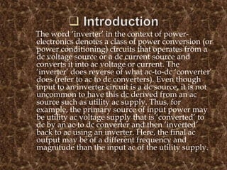
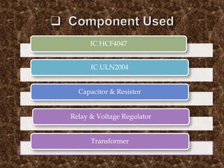
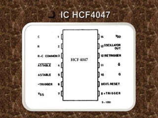
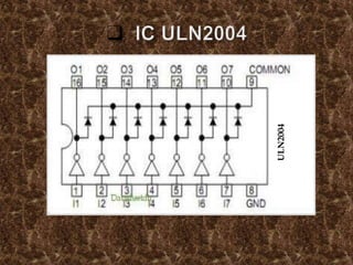
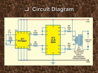


The document discusses the concept of inverters in power electronics, detailing their function in converting DC to AC voltage or current. It describes a specific low-power inverter circuit built around ICs CD4047 and ULN2004, which can convert 12V DC to 230-250V AC for light loads and offers benefits such as portability and efficiency. The document also outlines advantages, disadvantages, and applications of inverters, including their use in uninterruptible power supplies and during power outages.


![Presentation_major_project_FINAL[1].pptx](https://cdn.slidesharecdn.com/ss_thumbnails/presentationmajorprojectfinal1-241214142519-b28732ef-thumbnail.jpg?width=640&height=640&fit=bounds)