The study explores the performance of polymer solar cells (PSCs) incorporating poly(3-hexylthiophene) (P3HT) and [6,6]-phenyl C61-butyric acid methyl ester (PCBM), focusing on the influence of temperature on their electrical parameters. It validates a one-diode electrical model using a combination of least mean squares (LMS) and Newton-Raphson algorithms to accurately extract parameters like efficiency and current-voltage characteristics. Results indicate a significant dependency of cell efficiency on temperature and other studied parameters, demonstrating promising advancements in the optimization of PSC performance.
![International Journal of Power Electronics and Drive Systems (IJPEDS)
Vol. 12, No. 3, September 2021, pp. 1772~1783
ISSN: 2088-8694, DOI: 10.11591/ijpeds.v12.i3.pp1772-1783 1772
Journal homepage: http://ijpeds.iaescore.com
Electrical and environmental parameters of the performance of
polymer solar cells based on P3HT:PCBM
El Hadi Chahid1
, Mohamed Lotfi2
, Osama Lotfi3
, My Abdelaziz Koumina4
, Rodolphe Heyd5
,
Abdessamad Malaoui6
1,6
Equipe de Recherche en Electronique, Instrumentation et Mesures, Faculté Polydisciplinaire, Université Sultan Moulay
Slimane, Beni Mellal, Morocco
2,4
Laboratoire Interdisciplinaire de Recherche en Bio-Ressources, Environnement et Matériaux, Ecole Normale
Supérieure, Marrakech, Morocco
2
Laboratoire Matériaux Energie Environnement, Faculté des Sciences Semlalia, Marrakech, Morocco
3
RES SARL, Beni Mellal, Morocco
5
Laboratoire Angevin de Mécanique, Procédés et innovAtion (LAMPA), Arts et Métiers ParisTech, Angers, France
Article Info ABSTRACT
Article history:
Received Nov 16, 2020
Revised Apr 26, 2021
Accepted Jul 16, 2021
The electrical and environmental parameters of polymer solar cells (PSC)
provide important information on their performance. In the present article we
study the influence of temperature on the voltage-current (I-V) characteristic
at different temperatures from 10 °C to 90 °C, and important parameters like
bandgap energy Eg, and the energy conversion efficiency η. The one-diode
electrical model, normally used for semiconductor cells, has been tested and
validated for the polemeral junction. The PSC used in our study are formed
by the poly(3-hexylthiophene) (P3HT) and [6,6]-phenyl C61-butyric acid
methyl ester (PCBM). Our technique is based on the combination of two
steps; the first use the Least Mean Squares (LMS) method while the second
use the Newton-Raphson algorithm. The found results are compared to other
recently published works, they show that the developed approach is very
accurate. This precision is proved by the minimal values of statistical errors
(RMSE) and the good agreement between both the experimental data and the
I-V simulated curves. The obtained results show a clear and a monotonic
dependence of the cell efficiency on the studied parameters.
Keywords:
Band gap
Efficiency
Photocurrent
Polymer
Solar cell
This is an open access article under the CC BY-SA license.
Corresponding Author :
El Hadi Chahid
Equipe de Recherche en Electronique, Instrumentation et Mesures (E.R.E.I.M)
Faculté Polydisciplinaire, Université Sultan Moulay Slimane
Beni Mellal, Morocco
Email: chahid2016@yahoo.com
1. INTRODUCTION
Currently, a continuous growing demand for clean sustainable energy has pushed academic as well
as industrial institutions to gain a deep understanding of solar cells. Much of today’s research focuses on the
cells development, material selection and manufacturing with the aim to enhance performance and reduce
cost. The current conventional photovoltaic is crystalline silicon known for its non-toxicity, abundance, high
and stable cell efficiencies. It has been dominating the solar panels market due to its nature material
technology and widespread knowledge, skills and infrastructure for manufacturing and assembly lines. The
upper limit of crystalline silicon solar cells efficiency is reaching 26.7% [1]. However, they have lower
energy conversion efficiency which make them less space efficient, limited flexibility and cannot be](https://image.slidesharecdn.com/21101-41410-2-pb-220128070121/75/Electrical-and-environmental-parameters-of-the-performance-of-polymer-solar-cells-based-on-P3HT-PCBM-1-2048.jpg)
![Int J Pow Elec & Dri Syst ISSN: 2088-8694
Electrical and environmental parameters of the performance of polymer solar … (El Hadi Chahid)
1773
manufactured in large scale. These limitations of silicon solar cells are some of the reasons that has led many
researchers to explore other alternative materials to overcome these issues.
Photovoltaic cells formed by organic polymers or organic molecules are solar cells potentially able
to increase the energy efficiency compared to the first and second generations. They are well known for their
lightweight, flexibility and low cost to fabricate where the manufacturing techniques vary from coating,
spraying and printing [2]. On the contrary, the main disadvantages associated with PSC when compared to
inorganic solar cells have low stability in the face of climatic variations and also a low energy efficiency.
However, these factors had made the organic solar cells a challenging and popular field of research. The
PSCs were able to achieve the highest efficiency of 2.5% as reported in [3], and continues to improve to a
record level of 17.35% as presented in solar cell efficiency tables [1], [4]. One of the major obstacles that
limit the energy conversion efficiency of organic solar cells lies in the intrinsic properties of the currently
used active materials such as, conjugated polymers, preparation and control of their structure (distribution of
different lengths of polymer chains in the material). In addition, the PSC tends to suffer from degradation
when exposed to harsh ambient conditions (temperature, humidity and rain) as the solar cells are sensitive to
high temperature [5], [6]. Several research groups are actively working to address these issues. For instance,
a study to investigate the effect of intrinsic parameters which are influenced on the organic cells
performance, such as Voc (open circuit voltage), Isc (short circuit current) and 𝜂 (power conversion efficiency)
was reported in [7]. Numerous models were also developed to represent the solar cell covering mainly the
number of diodes, the shunt resistor and ideality factor. For example, the single diode model M1DR in [8]
and two diodes model M2DR in [9]. We consider in the single diode model the following five parameters:
the photocurrent Iph, the reverse saturation current I0, the series resistance Rs, the shunt resistance Rsh, and the
diode ideality factor n [10], [11]. The second problem is focused on the temperature effect of the (I-V)
characteristic solar cell. This dependence is described by the sensitivity of the different electrical parameters
of the organic photovoltaic generator (Voc, Isc, 𝜂, and Pmax) when the temperature varies. Indeed, the variation
of the short circuit current in a remarkable manner, however the open circuit voltage is insensitive to the
variation of the temperature [12]-[16]. In literature, several numerical methods were developed for extracting
electrical parameters solar cells, such as the least square method, the Newton’s method, and the Levenberg
Marquardt’s method [17]-[20]. As is justified in the literature, an accurate optimization method for
parameters extracting is based on the minimization of root mean square error (RMSE) between the theoretical
and experimental values to verify the effectiveness of the proposed model [21], [22].
The aim of the current study is to investigate the effect of temperature on the electrical parameters
of the polymer solar cells (PSCs) based on poly (3-hexylthiophene) (P3HT) and [6,6]-phenyl C61-butyric
acid methyl ester (PCBM). To further enhance the energy conversion efficiency, a developed model of the
PSC device using single diode will be presented together with the proposed numerical optimization based on
the combination of both the Least Square Method (LMS) and the Newton-Raphson (N-R) Algorithm.
2. STRUCTURE AND OPERATION OF POLYMER SOLAR CELL
The general structure of PSC device consists of a transparent substrate such as (glass, quartz,
plastic), coated with an electrode, indium tin oxide (ITO), which should be transparent in order to allow the
incoming photons to reach the photoactive layer. In addition, a bi-layer of two organic components, with one
as the electron donor and the other as the electron acceptor, and finally one top metal electrode, as seen in
Figure 1. This bilayer of PSC is the photoactive layer which composes of donor layer and acceptor layer.
A schematic of the basic operation of a PSC is illustrated in Figure 2. the four main steps to produce
electrical energy from solar energy by the solar cell are summarized as: i) creation of electron-hole pairs so-
called excitons by photons; ii) the excitons formed diffuse towards the donor-acceptor interface (D/A); iii)
the minority charge carriers which are the holes in the donor region and the electrons in the acceptor region,
move to the contacts for collection due to the internal electric potential/field in the junction; and iv)
collecting The charge carriers associate at the electrodes and thus create an electric current.
Figure 3 shows the operation mechanism in P3HT/PCBM cell. The exciton formed is generated,
when the incident photon has energy greater than the bandgap energy Eg of the P3HT. Thus, an electron in
the highest occupied molecular orbit (HOMO) would be excited to the lowest unoccupied molecules orbital
(LUMO), leaving a hole HOMO band. On the other hand, an efficient solar cell should have a wide
absorption spectrum, to create as many pairs as possible of excitons charges due to the Shockley and
Queisser limitation [22].](https://image.slidesharecdn.com/21101-41410-2-pb-220128070121/75/Electrical-and-environmental-parameters-of-the-performance-of-polymer-solar-cells-based-on-P3HT-PCBM-2-2048.jpg)
![ ISSN: 2088-8694
Int J Pow Elec & Dri Syst, Vol. 12, No. 3, September 2021 : 1772 – 1783
1774
Figure 1. structure of a bilayer
polymer solar cell device
Figure 2. Operation mechanism of a bilayer polymer solar cell
device (D=donor, A= acceptor)
Figure 3. A general operation mechanism in a bilayer P3HT: PCBM cell
The created excitons can be separated if they encounter an internal electric field in the junction.
Electrons move from LUMO donor to LUMO acceptor while the holes located in the HOMO acceptor and
flows to HOMO donor. However, the diffusion length of charge carriers which is very short makes this
process inefficient. Furthermore, the generated charge would be collected at electrodes and more efficient
charge collection by utilizing metal oxide-organic interface to decrease surface resistivity and metal oxide-
organic to facilite hole-extraction [23]-[25]. This transfer of carrier charges within the heterojunction, formed
by the donor and acceptor of organic semiconductor D/A can produce an open circuit voltage 𝑉
𝑜𝑐which is
defined as reported in [26]:
𝑞𝑉
𝑜𝑐 = 𝐸𝐻𝑂𝑀𝑂
𝐷
− 𝐸𝐿𝑈𝑀𝑂
𝐴
− 𝐸𝑒𝑥 (1)
Where, 𝐸𝐻𝑂𝑀𝑂
𝐷
and 𝐸𝐿𝑈𝑀𝑂
𝐴
are the acceptor energy LUMO and the donor energy HOMO
respectively, 𝐸𝑒𝑥 is the exciton binding energy, and 𝑞 is the elementary electric charge.
3. MODELING OF PSC
The one diode model of polymer solar cell under illumination and the equivalent circuit model is
illustrated in Figure 4. The equation of current I as a function of voltage V is written as [20]:
𝐼(𝑉) = 𝐼𝑝ℎ − 𝐼0 [𝑒
𝑞(𝑉+𝐼𝑅𝑠)
𝑛𝑘𝑇 − 1] −
𝑉+𝐼𝑅𝑠
𝑅𝑠ℎ
(2)](https://image.slidesharecdn.com/21101-41410-2-pb-220128070121/75/Electrical-and-environmental-parameters-of-the-performance-of-polymer-solar-cells-based-on-P3HT-PCBM-3-2048.jpg)
![Int J Pow Elec & Dri Syst ISSN: 2088-8694
Electrical and environmental parameters of the performance of polymer solar … (El Hadi Chahid)
1775
Figure 4. Equivalent circuit model of a polymer solar cell
Where, 𝐼𝑝ℎ and 𝐼0 are the photocurrent and reverse saturation current, the series and parallel resistances are
noted as 𝑅𝑠 and 𝑅𝑠ℎ, the ideal factor symbol is noted 𝑛 , the Boltzmann’s constant is noted k, and the
temperature cell is noted T and expressed by (𝐾).
The photocurrent generated by the cell varies linearly on solar irradiation and is also influenced by
the temperature according to the (3) [27]-[29]:
𝐼𝑝ℎ = (𝐼𝑝ℎ,𝑟𝑒𝑓 + 𝜆𝑠𝑐(𝑇 − 𝑇𝑟𝑒𝑓)) (
𝐺
𝐺𝑟𝑒𝑓
) (3)
Where, 𝐼𝑝ℎ,𝑟𝑒𝑓 is the photocurrent of the module at Standard Test Conditions (STC) (usually 25 ◦
C and
1000W/m2
), 𝑇𝑟𝑒𝑓 is the reference temperature of the PSC which is given on the data sheet, 𝜆𝑠𝑐 is the
temperature coefficient of short current which is found on the data sheet and is expressed by (𝐴 𝐾)
⁄ , 𝐺 is the
irradiation on the device surface (in 𝑊 𝑚2
⁄ ), and 𝐺𝑟𝑒𝑓 is the reference irradiation. The relationship between
𝐼0 as a function of the temperature 𝑇 is given by the empirical by Green [30]:
𝐼0 = 𝐴exp − (
𝑞𝐸𝑔
𝑘𝑇
) (4)
Where 𝐴 is a constant equal to 1,5 × 10⁸
𝑚𝐴. 𝑐𝑚−2
and 𝐸𝑔 represents the band gap energy. The expression of
external quantum efficiency (EQE) is the ration between the electrical energy and the incident photon flux.
Then, the EQE is given by [31], [32]:
𝐸𝑄𝐸(%) = 1240 ×
𝐽𝑠𝑐(𝜆)
𝜆×𝜑𝜆(𝑇)
× 100 (5)
Where, 𝜑𝜆(𝑇) is the monochromatic light intensity (𝑚𝑊 𝑐𝑚2
⁄ ). 𝐽𝑠𝑐(𝜆) is the photocurrent density
(𝑚𝐴 𝑐𝑚2
⁄ ), 𝜆 is monochromatic wavelength of light (𝑛𝑚).The 𝐸𝑄𝐸 equal to unit if all photons are observed
by the semiconductor. The expression of incident photon flux which depends especialy with the body’s
temperature 𝑇(𝐾) is given by Planck’s law [33], [34]:
𝜑𝜆(𝑇) =
2𝜋ℎ𝑐2
𝜆5
1
𝑒ℎ𝑐 𝜆𝑘𝐵𝑇
⁄ −1
(6)
Where, ℎ is the Planck's constant, 𝑘𝐵 is the Boltzmann's constant, and 𝑐 is the speed of light in vacuum, 𝑇 is
the temperature of the black body. The used Planck’s law is implemented in a MATLAB script which yields
the photon flux of the black body, and it is represented in Figure 5.
On the other hand, the generated current density 𝐽𝑠𝑐 ,by the PSC with incoming solar radiation, can
be calculated from the external quantum efficiency 𝐸𝑄𝐸(𝜆, 𝑇). This evaluation is obtained by integrating
over the entire solar radiation spectrum [35]:
𝐽𝑠𝑐 = 𝑞 ∫ 𝐸𝑄𝐸(𝜆)𝜑𝜆(𝑇)
𝜆𝑚𝑎𝑥
𝜆𝑚𝑖𝑛
𝑑𝜆 (7)
Where, 𝜑𝜆(𝑇) is the photon flux of solar radiation spectrum under AM1.5. Then, the short circuit current can
be deduced using the area of the illuminated dvice noted 𝐴. It s written as: 𝐼𝑠𝑐 = 𝐴 × 𝐽𝑠𝑐.](https://image.slidesharecdn.com/21101-41410-2-pb-220128070121/75/Electrical-and-environmental-parameters-of-the-performance-of-polymer-solar-cells-based-on-P3HT-PCBM-4-2048.jpg)
![ ISSN: 2088-8694
Int J Pow Elec & Dri Syst, Vol. 12, No. 3, September 2021 : 1772 – 1783
1776
Figure 5. The incident photon flux for an AM1.5 solar radiation spectrum at 6000 𝐾
4. ELECTRICAL PARAMETERS OF AN PSC
The most important parameter of a PSC is the power conversion efficiency(η), which represents the
ability of the cell to convert light into electricity. It is defined as the ratio between the maximum power
output 𝑃𝑚𝑎𝑥 and the incident power 𝑃𝑖𝑛𝑐 = 100 𝑊/𝑚2
at (STC). It is written as:
𝜂 =
𝑃𝑚𝑎𝑥
𝑃𝑖𝑛𝑐
× 100% =
𝐹𝐹×𝑉𝑜𝑐×𝐼𝑠𝑐
𝑃𝑖𝑛𝑐
× 100 (8)
Where 𝐹𝐹 is the Fill Factor corresponding to the maximum power ratio on the ideal theoretical power. FF
describes the part of energy loss in the form of Joule heat, which mainly determined by surface resistivity and
it expressed as:
𝐹𝐹 =
𝑃𝑚𝑎𝑥
𝑉𝑜𝑐.𝐼𝑠𝑐
× 100% =
𝑉𝑚𝑎𝑥.𝐼𝑚𝑎𝑥
𝑉𝑜𝑐.𝐼𝑠𝑐
× 100% (9)
The short circuit current 𝐼𝑠𝑐 is the current when the voltage across the device is zero, and the open-circuit
voltage 𝑉
𝑜𝑐 is the voltage when the current in the device is zero. According to the (9) and (10), it is clear that
a high efficiency could be reached with higher 𝑉
𝑜𝑐, 𝐼𝑠𝑐 and 𝐹𝐹. The voltage 𝑉
𝑜𝑐 can be expressed as a function
of the currents 𝐼𝑠𝑐 and 𝐼0. It can be written as [30]:
𝑉
𝑜𝑐 =
𝑛𝑘𝑇
𝑞
ln (
𝐼𝑠𝑐
𝐼0
− 1) (10)
5. DEVELOPED METHOD OF EXTRACTING ELECTRICAL PARAMETERS
Determining the final optimal parameters values requires first an estimation of the initial guess
assigned to the extracted parameters 𝜃0[𝐼𝑝ℎ, 𝐼0, 𝑅𝑠, 𝑅𝑠ℎ, 𝑛]; which affect the convergence of the Newton-
Raphson’s algorithm (N-R). The initial parameters 𝜃0 are obtained from the current-voltage experimental
curve using the least mean square (LMS) method. This technique is one of the most widely used methods for
modeling experimental measurements by a predetermined analytical function given by (2). This method
consists to minimize the mean absolute or relative difference between the N measures Im (Vi) and the
calculated values of electric current Ic (Vi) obtained by (2). The mathematical model of single diode for
estimation five parameters in the form as:
𝑓(𝐼𝑖, 𝑉𝑖, 𝜃) = 𝐼𝑝ℎ − 𝐼0 [𝑒
𝑞(𝑉+𝐼𝑅𝑠)
𝑛𝑘𝑇 − 1] −
𝑉+𝐼𝑅𝑠
𝑅𝑠ℎ
− 𝐼 (11)
The second step, we use the N-R algorithm to determine the final five unknown electrical
parameters 𝜃[𝐼𝑝ℎ, 𝐼0, 𝑅𝑠, 𝑅𝑠ℎ, 𝑛] which characterize the single diode model of the polymer solar cell. The N-R
method is widely used in finding the root of nonlinear equations. This method uses the derivative of f(x) at x
to estimate a new value of the root. The desired precision is reached by iteration. if θi+1 is an approximation
to the root of f(θ) = 0. The N-R is an iterative method that estimate the root of a real valued nonlinear
function f(𝜃) with an initial guess 𝜃0. This linearization process is obtained through the first order Taylor’s
series expansion (linear in 𝜃) to the first around the guess (𝜃𝑖), which is given below [36]:](https://image.slidesharecdn.com/21101-41410-2-pb-220128070121/75/Electrical-and-environmental-parameters-of-the-performance-of-polymer-solar-cells-based-on-P3HT-PCBM-5-2048.jpg)
![Int J Pow Elec & Dri Syst ISSN: 2088-8694
Electrical and environmental parameters of the performance of polymer solar … (El Hadi Chahid)
1777
𝑓(𝜃𝑖+1) = 𝑓(𝜃𝑖) + (𝜃𝑖+1 − 𝜃𝑖)𝑓′(𝜃𝑖) + ⋯ = 0 (12)
Therefore, the next approximation to the root 𝜃𝑖 in the ith iterative step is given by the iterative formula [37]:
𝜃𝑖+1 = 𝜃𝑖 − 𝑓(𝜃𝑖) 𝑓′(𝜃𝑖)
⁄ (13)
The procedure is repeated until |𝜃𝑖+1 − 𝜃𝑖| < 𝜀, where 𝜀 is a perset tolerance. The N-R method is easily
extended to the solution of set of n-nonlinear equations, where 𝑛 ≥ 2. Therefore, the parameters 𝜃 are
evaluated at each iteration according to the formula [21]:
𝜃𝑖 = 𝜃𝑖−1 − [J(θ)]θi−1
−1
× [𝑓]θi−1
(14)
Where J is the Jacobian matrix for the function 𝑓(𝜃) given by the first-order contains the partial derivatives at
each parameter of the vector 𝜃𝑖. It is defined by: 𝐽𝑖𝑗 =
𝜕𝑓𝑖
𝜕𝜃𝑗
, ∆𝜃 = 𝜃𝑖 − 𝜃𝑖−1 denotes the change in the value of
the vector of roots (step size). The used function 𝜑 to optimize the electrical parameters is the objective
function 𝜑, which is defined as the difference between both of the experimental 𝐼𝑒𝑥𝑝
and calculated 𝐼𝑐𝑎𝑙
electric current values. The expression of φ can be given by:
𝜑(𝐼𝑖, 𝑉𝑖, 𝜃) = ∑ (𝐼𝑖
𝑒𝑥𝑝
− 𝐼𝑖
𝑡ℎ𝑒
)
2
𝑁
𝑖=1 = ∑ 𝑒𝑖
2
(𝜃𝑖)
𝑁
𝑖=1 (15)
Where, 𝑒𝑖 = 𝐼𝑖
𝑒𝑥𝑝
− 𝐼𝑖
𝑐𝑎𝑙
, is the error between the experimental and theoretical electric currents 𝐼𝑖
𝑒𝑥𝑝
and 𝐼𝑖
𝑐𝑎𝑙
respectively, and 𝑁 is the number of measurements. To validate our adopted method and evaluates its degree
of precision, we use the root mean square error (RMSE) which is written as:
RMSE = √
1
N
∑ (e(Ii, Vi, θ𝑖))
2
N
i=1 (16)
Where (Ii, Vi) represents the 𝑖𝑡ℎ measured value of N experimental data. In a MATLAB script, the flowchart
of the developed method is shown in Figure 6.
Figure 6. Flowchart for estimation PSCs parameters using the developed method](https://image.slidesharecdn.com/21101-41410-2-pb-220128070121/75/Electrical-and-environmental-parameters-of-the-performance-of-polymer-solar-cells-based-on-P3HT-PCBM-6-2048.jpg)
![ ISSN: 2088-8694
Int J Pow Elec & Dri Syst, Vol. 12, No. 3, September 2021 : 1772 – 1783
1778
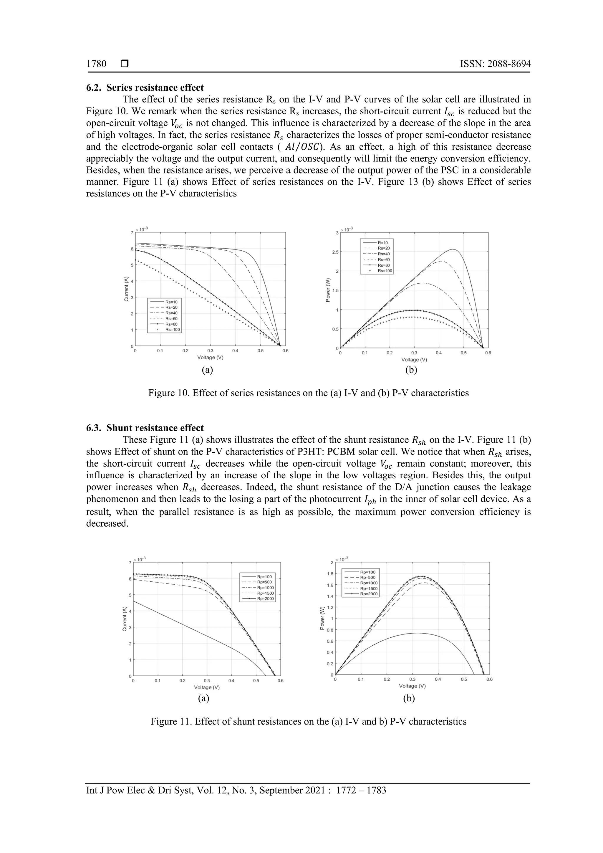
6. RESULTS AND DISCUSSION
In this section, we will present the results of the theoretical research related to the dependence of the
PSCs energy conversion efficiency with the temperature and the intrinsic electrical parameters by using the
single diode model. The simulated results of I-V characteristic, under the Standard Test Conditions (𝑆𝑇𝐶) at
𝐴𝑀1.5, were carried out using the developed method which is composed of two means. The first one is the
least mean square method (LMS) so as to determine the initial electrical parameters 𝜃0[𝐼𝑝ℎ, 𝐼0, 𝑅𝑠, 𝑅𝑠ℎ, 𝑛],
and the second one is the Newton- Raphson’s algorithm (N-R) to evaluate the final optimal values.
Figure 7 shows both the calculated and experimental curves of the P3HT: PCBM polymer solar cell.
That is, the experimental curve was represented by the squares in the Figure 7, whose the data points (𝐼𝑖, 𝑉𝑖)
with (𝑖 = 1, … ,36) are from the reference cell [38], what’s more, the calculated curve was schematized by
the solid line.
As it is shown in Figure 7, there is a very good agreement between the simulation results and the
experimental data (Ii, Vi). In the developed method, the LMS method is used to determine the initial
parameters so as to ensure the convergence of the Newton’s algorithm. The final values of the five
parameters are substituted in (2), and are obtained while the error criterion ∆𝜃 = |𝜃𝑖+1 − 𝜃𝑖| is minimized.
Then the PSC’s parameters which are found by the developed method are listed in Table 1 and compared to
the references work.
Figure 7. Calculated and experimental I-V characteristics of P3HT: PCBM polymer solar cell
Table 1. Comparaison of estimated parameters for single diode model of PSC
Electrical Parameters Proposed method Ref[39] Ref[40] Ref[41]
𝑰𝒑𝒉(𝒎𝑨)
𝑰𝒔(𝑨)
𝒏
𝑹𝒔𝒉()
𝑹𝒔()
6.59
1.46×10⁻¹⁴
0.84
1038.13
38.85
6.4
2.00×10-08
3.027
36200
107.42
6.4
2.63×10⁻¹⁰
1.363
36300
35.46
6.4
2.21×10⁻¹²
1.068
36400
38.24
From the results presented in Table 1, it is clearly seen that the five electrical parameters evaluated
by the proposed method are quite closer than those found in the references [39]-[41]. The highest precision of
the extracted values is directly attached to the lowest value of the root mean squared error (RMSE), which
measures the average of squared differences between prediction and real in a set of electric current values.
The found values of the statistical error (RMSE) are presented in Table 2 and compared to the reference
values [39]-[41].
Table 2. Statistical error (RMSE)of electrical parameters model
Statistical Error Proposed Method Ref[39] Ref[40] Ref[41]
RMSE 1.0012×10⁻⁴
2.3423×10⁻³
1.4936×10⁻³
6.3944×10⁻⁴
According to the statistical error, the obtained value by the proposed method is lower than those
found by other works [39]-[41]. As a result, our proposed method is more accurate than the other methods. In
addition, the program’s execution is fairly fast than the other programs. In what follows, we will study the](https://image.slidesharecdn.com/21101-41410-2-pb-220128070121/75/Electrical-and-environmental-parameters-of-the-performance-of-polymer-solar-cells-based-on-P3HT-PCBM-7-2048.jpg)
![Int J Pow Elec & Dri Syst ISSN: 2088-8694
Electrical and environmental parameters of the performance of polymer solar … (El Hadi Chahid)
1779
effect of the influence of many factors on the PSC operation, such as: temperature, series and shunt
resistances, ideality factor and illumination. This effect will be shown through both the variation of I-V and
P-V characteristics in order to optimize the energy conversion efficiency of polymer solar cell.
6.1. Temperature cell effect on PSC parameters
The Figure 8 shows the impact of the temperature cell ranging from 10°C to 90°C on the I-V and P-
V characteristics of the P3HT: PCBM polymer solar cell. It is observed that the increase of the temperature
produces an increase in the short-circuit current (Isc) and a decrease in open circuit voltage (Voc). On the other
hand, the increase in the temperature leads to a decrease in maximum voltage (Vm) and a slight increase in
maximum current (Im) and consequently a relative decrease in maximum power (Pmax). Figure 8 (a) shows
Effect of temperature on the I-V. Figure 8 (b) shows Effect of temperature on the P-V characteristics.
(a) (b)
Figure 8. Effect of temperature on the (a) I-V and (b) P-V characteristics
Figure 9 represents the variation of the gap energy and the energy conversion efficiency of PSC as a
function of temperature. It is seen that both the cell efficiency 𝜂(%) and the bandgap energy 𝐸𝑔 decreases
when the temperature 𝑇 increases as described by Varshni’s empirical expression [42]. Figure 9 (a) shows
Efficiency. Figure 9 (b) shows band gap energy of PSC as a function of temperature.
(a) (b)
Figure 9. (a) Efficiency and (b) band gap energy of PSC as a function of temperature
𝐸𝑔(𝑇) = 𝐸𝑔(0) −
𝛼𝑇2
𝑇+𝛽
(17)
Where 𝐸𝑔(0) is the bandgap energy at theoretical zero temperature of material, and are material
constants. As a suggestion, to enhance the PSC’s performance could be achieved through the choice of new
material in the solar cell domain like perovskite material which is a hybrid of organic and inorganic material
[43], [44].](https://image.slidesharecdn.com/21101-41410-2-pb-220128070121/75/Electrical-and-environmental-parameters-of-the-performance-of-polymer-solar-cells-based-on-P3HT-PCBM-8-2048.jpg)
![Int J Pow Elec & Dri Syst ISSN: 2088-8694
Electrical and environmental parameters of the performance of polymer solar … (El Hadi Chahid)
1781
6.4. Influence of the ideality factor
These Figure 12 (a) shows the influence of the ideality factor n on the I-V and Figure 12 (b) shows
the influence of the ideality factor n on the P-V characteristics of the solar cell under the Standard Test
Conditions. It can be seen that the decrease of the ideality factor n causes a reduction in the open circuit
voltage Voc, while the short-circuit current Isc remains constant.
(a) (b)
Figure 12. Effect of ideality factor n on the (a) I-V and (b) P-V characteristics
6.5. Illumination effect
Figure 13 represents the current-voltage and power-voltage characteristics of a polymer solar cell
for different solar irradiation ranging from 𝐸 = 200 𝑊 𝑚2
⁄ to 𝐸 = 1400 𝑊 𝑚2
⁄ . We notice that the short-
circuit current Isc increases significantly comparing to the open circuit voltage 𝑉
𝑜𝑐. In fact, the short-circuit
current varies linearly as a function of the illumination, whereas the open circuit voltage varies
logarithmically [29], [30] as a function of the illumination. As a result, the increase of solar irradiation causes
an increase in the maximum voltage Vm, the maximum current Im and subsequently a net increase in the
maximum power Pmax. Figure 13 (a) shows Effect of illumination on the I-V. Figure 13 (b) shows Effect of
illumination on the P-V characteristics.
(a) (b)
Figure 13. Effect of illumination on the (a) I-V and (b) P-V characteristics
7. CONCLUSION
In this paper, we have studied the dependence both of the intrinsic electrical and the external
parameters (illumination, temperature, series and parallel resistances, and ideality factor) on the performance
of polymer solar cells (PSCs) based on the poly(3-hexylthiophene) (P3HT) and [6,6]-phenyl-C61-butyric
acid methyl ester (PCBM). The single diode model is used to represent the PSC, which is identified by the
five electrical parameters (Iph, I0, Rs, Rsh, and n). The proposed method performed by the combination of least](https://image.slidesharecdn.com/21101-41410-2-pb-220128070121/75/Electrical-and-environmental-parameters-of-the-performance-of-polymer-solar-cells-based-on-P3HT-PCBM-10-2048.jpg)
![ ISSN: 2088-8694
Int J Pow Elec & Dri Syst, Vol. 12, No. 3, September 2021 : 1772 – 1783
1782
mean square method (LMS) and the Newton Raphson’s method to determine the final optimal values of the
PSC’s parameters.
The effect of temperature on both the I-V and P-V characteristics, energy band gap, and the energy
conversion efficiency at different temperatures from 10°C and 90°C has studied, and the influence of the
electrical and environmental parameters on both of the I-V and P-V characteristic’s PSC. The obtained
results show that the calculated currents are in a good agreement with the experimental data, and the
difference between both of the calculated and the experimental currents does not exceed 10% referring to the
RMSE statistical error. Concerning the effect of the temperature, we have found an increase of Isc, a decrease
of Voc with increasing of the temperature. However, the variation of the intrinsic electrical parameters shows
a dependence of the PSC’s efficiency, that we can use in the improvement of PSC performance by taking the
optimal intrinsic and external parameters.
REFERENCES
[1] M. A. Green, E. D. Dunlop, J. Hohl-Ebinger, M. Yoshita, N. Kopidakis, and A. W. Y. Ho-Baillie, “Solar cell
efficiency tables (version 55),” Progress in Photovoltaics: Research and Applications, vol. 28, no. 1, pp. 3-15,
2020, doi: 10.1002/pip.3228.
[2] Z. Yin, J. Wei, and Q. Zheng, “Interfacial materials for organic solar cells: recent advances and perspectives,”
Advenced Science, vol. 3, no. 8, pp. 1-37, 2016, doi: 10.1002/advs.201500362.
[3] S. Shaheen, C. Brabec, N. S. Sariciftci, F. Padinger, T. Fromherz, and J. Hummelen “2.5% efficient organic plastic
solar cells,” Applied Physics Letters, vol. 78, pp.841-843, 2001, doi: 10.1063/1.1345834.
[4] Z. Li et al, “A generic green solvent concept boosting the power conversion efficiency of all‐polymer solar cells to
11%,” Energy Environmental Science, vol. 12, pp. 157‐163, 2019, doi: 10.1039/C8EE02863J.
[5] E. Bundgaard, O. Hagemann, M. Manceau, M. Jorgensen, and F. Krebs, “Low band gap polymers for roll-to-roll
coated polymer solar cells,” Macromolecules, vol. 43, no. 19, pp. 8115-8120, Aug 2010, doi: 10.1021/ma1015903.
[6] M. Jørgensen, K. Norrman, and F. C. Krebs, “Stability/degradation of polymer solar cells,” Solar Energy Materials
and Solar Cells, vol. 92, no. 7, pp. 686-714, July 2008, doi: 10.1016/j.solmat.2008.01.005.
[7] D. T. Cotfas, P.A. Cotfas, and S. Kaplanis, “Methods to determine the parameters of solar cells: a critical review,”
Renewable and Sustainable Energy Reviews, vol. 28, pp. 588-596, 2013, doi: 10.1016/j.rser.2013.08.017.
[8] E. Chahid, and M. Idali Oumhand. A. Malaoui, “A fast Strategy to determine the physical and electrical parameters
of photovoltaic silicon cell,” International Journal of Applied Power Engineering (IJAPE), vol. 6, no. 2, pp. 103-
112, 2017, doi: 10.11591/ijape.v6.i2.pp103-112.
[9] A. Malaoui, E. Barah, and J. Antari, “Implementation a new approach for modeling and determining the electrical
parameters of solar cells,” International Journal of Innovation and Applied Studies, vol. 15, no. 2, pp. 329-338,
2016.
[10] E. Chahid, M. I. Oumhand, M. Feddaoui, M. Erritali, and A. Malaoui, “Effect of measurement factors on
photovoltaic cell parameters extracting,” International Journal of Electrical and Computer Engineering (IJECE),
vol. 7, no.1, pp. 50-57, Feb 2017, doi: 10.11591/ijece.v7i1.pp50-57.
[11] A. Malaoui, “New method for improving the quality of electrical measurements: application to the extraction of the
intrinsic parameters of the photovoltaic cells,” International Journal of Innovation and Applied Studies, vol. 15, no.
2, pp. 375-386, 2016.
[12] S. Chander, A. Purohit, A. Sharma, Arvind, S. P. Nehra, and M. S. Dhaka, “A study on photovoltaic parameters of
monocrystalline silicon solar cell with cell temperature,” Energy Reports, vol. 1, pp. 104-109, 2015, doi:
10.1016/j.egyr.2015.03.004.
[13] O. Dupré, R. Vaillon, and M. A. Green, “Experimental assessment of temperature coefficient theories for silicon
solar cells,” IEEE Journal of Photovoltaics, vol. 6, no. 1, pp. 56-60, Jan. 2016, doi:
10.1109/JPHOTOV.2015.2489864.
[14] P. Singh, and N. M. Ravindra, “Temperature dependence of solar cell performance—an analysis,” Solar Energy
Materials and Solar Cells, vol. 101, pp. 36-45, 2012, doi: 10.1016/j.solmat.2012.02.019.
[15] A. B. Or, J. Appelbaum, “Dependence of multi-junction solar cells parameters on concentration and temperature,”
Solar Energy Materials and Solar Cells, vol. 130, pp. 234–240, 2014, doi: 10.1016/j.solmat.2014.07.010.
[16] D. T. Cotfas, P. A. Cotfas, and O. M. Machidon, “Study of temperature coefficients for parameters of photovoltaic
cells,” International Journal of Photoenergy, vol. 130, pp. 1-12, 2018, doi: 10.1155/2018/5945602.
[17] W. T. Vettering, and S. A. Teukolsky, Numerical recipes in C: the art of scientific computing, 2nd edition, UK:
Cambridge University Press, WH. Press, pp. 1-949, 1992.
[18] M. K. Gupta, and R. Jain, “Design and simulation of photovoltaic cell using decrement resistance algorithm,”
Indian Journal of Science and Technology, vol. 6, no. 5, pp. 4537-4541, 2013, doi: 10.17485/ijst/2013/v6i5.21.
[19] D. Marquardt, “An algorithm for least squares estimation of non linear parameters,” Journal of the Society for
Industrial and Applied Mathematics, vol. 11, no. 2, pp. 431-41, 1963.
[20] K. Bouzidi, M. Chegaar, and A. Bouhemadou, “Solar cells parameters evaluation considering the series and shunt
resistance,” Solar Energy Materials & Solar Cells, vol. 91, no. 18, pp. 1647-1651, 2007, doi:
10.1016/j.solmat.2007.05.019.
[21] F. Dkhichi, B. Oukarfi, A. Fakkar, and N. Belbounaguia, “Parameter identification of solar cell model using
Levenberg–Marquardt algorithm combined with simulated annealing,” Solar Energy, vol. 110, pp. 781–788, 2014.](https://image.slidesharecdn.com/21101-41410-2-pb-220128070121/75/Electrical-and-environmental-parameters-of-the-performance-of-polymer-solar-cells-based-on-P3HT-PCBM-11-2048.jpg)
![Int J Pow Elec & Dri Syst ISSN: 2088-8694
Electrical and environmental parameters of the performance of polymer solar … (El Hadi Chahid)
1783
[22] W. Shockley, and H. Queisser, “Detailed balance limit of efficiency of p-n junction solar cells,” Journal of Applied
Physics, vol. 32, no. 3, pp. 510-519, 1961, doi: /10.1016/j.solener.2014.09.033.
[23] B. Kippelen, and J. Bredas, “Organic photovoltaics,” Energy & Environmental Science, vol. 2, pp. 251-261, 2009,
doi: 10.1039/B812502N.
[24] L. Hung, C. Tang, and M. Mason, “Enhanced electron injection in organic electroluminescence devices using an
Al/LiF electrode,” Applied Physics Letters, vol. 70, no. 2, pp. 152-154, 1997, doi: 10.1063/1.118344.
[25] R. A. Hatton, N. P. Blanchard, L. W. Tan, G. Latini, F. Cacialli, and S. R. Silva, “Oxidised carbon nanotubes as
solution processable, high work function hole-extraction layers for organic solar cells,” Organic Electronics,
vol. 10, no. 3, pp. 388-395, 2009, doi: 10.1016/j.orgel.2008.12.013.
[26] J. Crispim, M. Carreira, and R. Castro, “Validation of photovoltaic electrical models against manufacturers data
and experimental results,” in 2007 International Conference on Power Engineering, Energy and Electrical Drives,
2007, pp. 556-561, doi: 10.1109/POWERENG.2007.4380161.
[27] D. Sera, R. Teodorescu, and P. Rodriguez, “PV panel model based on datasheet values,” in 2007 IEEE
International Symposium on Industrial Electronics, 2007, pp. 2392-2396, doi: 10.1109/ISIE.2007.4374981.
[28] W. De Soto, S. A. Klein, and W. A. Beckman, “Improvement and validation of a model for photovoltaic array
performance,” Solar Energy, vol. 80, no. 1, pp. 78-88, 2006, doi: 10.1016/j.solener.2005.06.010.
[29] A. Driesse, S. Harrison, and P. Jain, “Evaluating the effectiveness of maximum power point tracking methods in
photovoltaic power systems using array performance models,” in 2007 IEEE Power Electronics Specialists
Conference, 2007, pp. 145-151, doi: 10.1109/PESC.2007.4341978.
[30] M. A. Green, Solar cells: Operating principles, technology and system applications, Englewood Cliffs, NJ,
Prentice-Hall, Inc., 1982.
[31] S. Dhar, T. Majumder, and S. P. Mondal, “Graphene quantum dot-sensitized ZnO nanorod/polymer schottky
junction UV detector with superior external quantum efficiency, detectivity, and responsivity,” ACS Applied
Materials & Interfaces, vol. 8, no. 46, pp. 31822-31831, 2016, doi: 10.1021/acsami.6b09766.
[32] J. J. L. Hmar, T. Majumder, S. Dhar, and S. P. Mondal, “Sulfur and Nitrogen Co-doped graphene quantum dot
decorated ZnO nanorod/polymer hybrid flexible device for photosensing applications,” Thin Solid Films, vol. 612,
pp. 274-283, 2016, doi: 10.1016/j.tsf.2016.06.014.
[33] R. Shankar, Principles of quantum mechanics, 2nd ed., Springer, New York, 1994.
[34] T. Fukushima, “Precise and fast computation of Lambert W-functions without transcendental function evaluations,”
Journal of Computational and Applied Mathematics, vol. 244, pp.77-89, 2013, doi: 10.1016/j.cam.2012.11.021.
[35] H. Zhao, “Light trapping for silicon solar cells: theory and experiment,” ph.D. dissertations, Dept of Physics,
Syracuse University, 2013.
[36] M. D. Smith, “Newton-Raphson technique,” 1998, Electronic document [Online] Available:
http://web.mit.edu/10.001/Web/Course_Notes/NLAE/node6.html. Accessed in October, 02, 2016.
[37] A. Ben-Israel, “A Newton-Raphson method for the solution of systems of equations,” Journal of Mathematical
Analysis and Applications, vol. 15, no. 2, pp. 243-252, 1966, doi: 10.1016/0022-247X(66)90115-6.
[38] G. Williams, Advances in organic photovoltaics and methods for effective solar cell parameter extraction,
University of Waterloo. Waterloo, On Canada. N2L 3G1, 2016.
[39] N. Nehaoua, Y. Chergui, and D. E Mekki, “Determination of organic solar cell parameters based on single or
multiple pin structures,” Vacuum, vol. 84, no. 2, pp. 326-329, 2009, doi: 10.1016/j.vacuum.2009.07.006.
[40] M. Chegaar, G. Azzouhi, and P. Mialhe, “Simple parameter extraction method for illuminated solar cells,” Solid
State Electronics, vol. 50, no. 7-8, pp. 1234-1237, 2006, doi: 10.1016/j.sse.2006.05.020.
[41] A. Jain, and A. Kapoor, “A new method to determine the diode ideality factor of real solar cell using Lambert W-
function,” Solar Energy Materials and Solar Cells, vol. 85, no. 3, pp. 391-396, 2005, doi:
10.1016/j.solmat.2004.05.022.
[42] Y. P. Varshni, “Temperature dependence of the energy gap in semiconductors,” Physica, vol. 34, no. 1, pp. 149-
154, 1967, doi: 10.1016/0031-8914(67)90062-6.
[43] P. Tonui, S. O. Osenia, G. Sharmab, Q. Yanc, and G. T. Mola, “Perovskites photovoltaic solar cells: An overview
of current status,” Renewable and Sustainable Energy Reviews, vol. 91, pp. 1025-1044, 2018, doi:
10.1016/j.rser.2018.04.069.
[44] M. A. Green, and A. Ho-Baillie, “Perovskite solar cells: the birth of a new era in photovoltaics,” ACS Energy
Letters, vol. 2, no. 4, pp. 822-830, 2017, doi: 10.1021/acsenergylett.7b00137.](https://image.slidesharecdn.com/21101-41410-2-pb-220128070121/75/Electrical-and-environmental-parameters-of-the-performance-of-polymer-solar-cells-based-on-P3HT-PCBM-12-2048.jpg)


