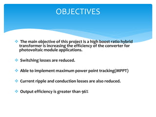
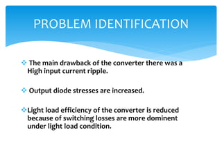
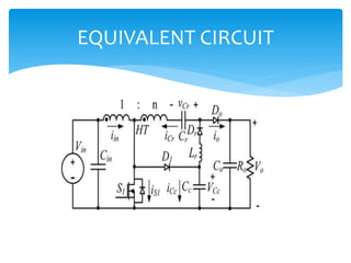
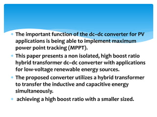
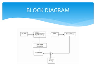
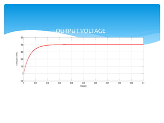
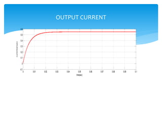
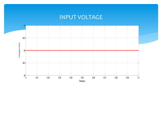
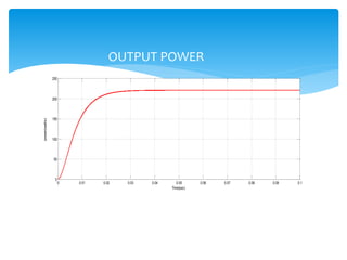
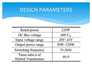
HIGH BOOST RATIO HYBRID TRANSFORMER
DC-DC CONVERTER FOR PHOTOVOLTAIC
MODULE APPLICATION
Under the guidance of
Mr.K.KRISHNA KUMAR
PRESENTED BY:
M.Anusha(11A21A0269)
L.Santosh kumar(11A21A0261)
M.Sai kumar(11A21A0262)
M.Rohith singh(11A21A0263)
 The main objective of this project is a high boost ratio hybrid
transformer is increasing the efficiency of the converter for
photovoltaic module applications.
 Switching losses are reduced.
 Able to implement maximum power point tracking(MPPT)
 Current ripple and conduction losses are also reduced.
 Output efficiency is greater than 96%
OBJECTIVES
 The main drawback of the converter there was a
High input current ripple.
 Output diode stresses are increased.
Light load efficiency of the converter is reduced
because of switching losses are more dominent
under light load condition.
PROBLEM IDENTIFICATION
Conventional systems
High step-up dc–dc converters using coupled-inductor and switched-capacitor
techniques.
(a) High-step coupled-inductor roboost dc-dc converter.
(b) High step-up dc-dc converter with coupled-inductor and switched-capacitor.
 PREVIOUS METHODS:
1.High step coupled inductor boost DC-DC converter
2. High step up DC-DC converter with coupled
inductor and
switched capacitor
 PROPOSED METHOD:
High boost ratio hybrid transformer DC-DC converter
SOLUTION METHODS
 The previous methods drawbacks are overcomed by using
high boost ratio hybrid transformer DC-DC converter.
This method is advantageous for a two stage PCS.
 By using this method, we achieve high level efficiency.
 The inductive and capacitive energy can be transferred
simultaneously to the high voltage DC bus.
 Increasing the total delivered power and decreases the
losses in the circuit.
 Adding resonant inductor and reducing the capacitance of
the switched capacitor in energy transfer path.
PROBLEM FORMULATION
 DC-DC conversion stage using PCS.
ABOUT PREVIOUS METHODS
 PCS accomplished single stage or double stage
 The double-stage PCS consists of a dc–dc conversion stage
that is connected to either a low power individual inverter.
 a high-power centralized inverter have multiple inverters.
 The high boost ratio dc–dc conversion stage of the PCS
requires a high efficiency.
 The high boost ratio DC-DC converter sare isolated or
non isolated .
 However, transformer-isolated converters tend to be
less efficient and more expensive due to the increased
manufacturing costs.
 A non isolated dc–dc converter with a high boost ratio
would be advantageous for a two-stage PCS
 Because it can be easily integrated with current PV
systems while reducing the cost and maintaining a
high system efficiency
Combination of coupled inductor and boost
converter:
 DC-DC converter with coupled inductor and switched
capacitor:
 The above methods was proposed to increase the boost
ratio without significant cost and efficiency penalties
 Light load efficiency of the converter is reduced because
switching losses were more dominant under light load
conditions.
 In this leakage inductance is produced. It provides severe
rigging and additional voltage stress on diode.
 Ripple current increased
 Now a days electric power is more important .
 Generating electric power from the renewable
energy sources.
 For that PV modules are increasing day by day.
 The output of the PV module is in b/w 20-45v.
 By using non isolated step up transformer DC-DC
converter
EXPLANATION
High boost ratio non isolated dc–dc converter ,a
clamp-mode couple-inductor buck–boost converter.
The converter’s leakage energy from the coupled-
inductor was recycled reducing the losses of the
system.
The output diode stress for this converter was similar
to that of a traditional fly back converter, i.e., higher
than the output dc bus voltage.

Another drawback of the converter was that there
was a high input current ripple due to the fact that
there was no direct energy
transfer path when the MOSFET was OFF.
Conventional System
EQUIVALENT CIRCUIT
C= input capacitor
HT= hybrid transformer with turns ratio 1:n
S1=active MOSFET switch
D1=clamping diode
Cc=clamped capacitor
Lr=resonant inductor
Cr=resonant capacitor
OPERATING MODES
 The important function of the dc–dc converter for PV
applications is being able to implement maximum
power point tracking (MPPT).
 This paper presents a non isolated, high boost ratio
hybrid transformer dc–dc converter with applications
for low-voltage renewable energy sources.
 The proposed converter utilizes a hybrid transformer
to transfer the inductive and capacitive energy
simultaneously.
 achieving a high boost ratio with a smaller sized.
From the circuit , we calculate boost ratio:
 The first flux balance on the magnetizing inductor of
hybrid transformer
Vcc =Vin/(1-D)
 Second flux, according to the flux balance on the
resonant inductor.
Vcr= nVin+Vcc =(n+1/(1-D))
 The last flux balance that governs circuit is voltage
second balance of the magnetizing inductor
VinD= (Vo-Vcr-Vin)/(1+n)*(1-D)
 The boost conversion ratio
Mb=Vo/Vin=n+2/n-D
BLOCK DIAGRAM
MODES OF OPERATION
SIMULATION CIRCUIT
0 0.01 0.02 0.03 0.04 0.05 0.06 0.07 0.08 0.09 0.1
-100
0
100
200
300
400
500
time(sec)
voltage(volts)
OUTPUT VOLTAGE
0 0.01 0.02 0.03 0.04 0.05 0.06 0.07 0.08 0.09 0.1
-0.1
0
0.1
0.2
0.3
0.4
0.5
0.6
time(sec)
current(amps)
OUTPUT CURRENT
0 0.01 0.02 0.03 0.04 0.05 0.06 0.07 0.08 0.09 0.1
39
39.5
40
40.5
41
Time(sec)
voltage(volts) INPUT VOLTAGE
0 0.01 0.02 0.03 0.04 0.05 0.06 0.07 0.08 0.09 0.1
0
50
100
150
200
250
Time(sec)
power(watts)
OUTPUT POWER
DESIGN PARAMETERS
 A high boost ratio dc–dc converter with
hybrid transformer suitable for alternative
dc energy sources with low dc voltage
input is proposed in this paper.
 The resonant conversion mode is
incorporated into a traditional high step-
up PWM converter with coupled-inductor
and switched-capacitor.
FUTURE SCOPE
CONCLUSION
1. J.-S. Lai, “Power conditioning circuit topologies,”
IEEE Ind. Electron. Mag., vol. 3, no. 2, pp. 24–34, Jun.
2009.2
2. S. B. Kjaer, J. K. Pedersen, and F. Blabber, “A review
of single-phase grid-connected inverters for
photovoltaic modules,” IEEE Trans. Ind. Appl., vol.
41, no. 5, pp. 1292–1306, Sep./Oct. 2005.
REFERENCES

power generation through solar power for PV module applications

  • 1.
    HIGH BOOST RATIOHYBRID TRANSFORMER DC-DC CONVERTER FOR PHOTOVOLTAIC MODULE APPLICATION Under the guidance of Mr.K.KRISHNA KUMAR PRESENTED BY: M.Anusha(11A21A0269) L.Santosh kumar(11A21A0261) M.Sai kumar(11A21A0262) M.Rohith singh(11A21A0263)
  • 2.
     The mainobjective of this project is a high boost ratio hybrid transformer is increasing the efficiency of the converter for photovoltaic module applications.  Switching losses are reduced.  Able to implement maximum power point tracking(MPPT)  Current ripple and conduction losses are also reduced.  Output efficiency is greater than 96% OBJECTIVES
  • 3.
     The maindrawback of the converter there was a High input current ripple.  Output diode stresses are increased. Light load efficiency of the converter is reduced because of switching losses are more dominent under light load condition. PROBLEM IDENTIFICATION
  • 4.
    Conventional systems High step-updc–dc converters using coupled-inductor and switched-capacitor techniques. (a) High-step coupled-inductor roboost dc-dc converter. (b) High step-up dc-dc converter with coupled-inductor and switched-capacitor.
  • 5.
     PREVIOUS METHODS: 1.Highstep coupled inductor boost DC-DC converter 2. High step up DC-DC converter with coupled inductor and switched capacitor  PROPOSED METHOD: High boost ratio hybrid transformer DC-DC converter SOLUTION METHODS
  • 6.
     The previousmethods drawbacks are overcomed by using high boost ratio hybrid transformer DC-DC converter. This method is advantageous for a two stage PCS.  By using this method, we achieve high level efficiency.  The inductive and capacitive energy can be transferred simultaneously to the high voltage DC bus.  Increasing the total delivered power and decreases the losses in the circuit.  Adding resonant inductor and reducing the capacitance of the switched capacitor in energy transfer path. PROBLEM FORMULATION
  • 7.
     DC-DC conversionstage using PCS. ABOUT PREVIOUS METHODS
  • 8.
     PCS accomplishedsingle stage or double stage  The double-stage PCS consists of a dc–dc conversion stage that is connected to either a low power individual inverter.  a high-power centralized inverter have multiple inverters.  The high boost ratio dc–dc conversion stage of the PCS requires a high efficiency.
  • 9.
     The highboost ratio DC-DC converter sare isolated or non isolated .  However, transformer-isolated converters tend to be less efficient and more expensive due to the increased manufacturing costs.  A non isolated dc–dc converter with a high boost ratio would be advantageous for a two-stage PCS  Because it can be easily integrated with current PV systems while reducing the cost and maintaining a high system efficiency
  • 10.
    Combination of coupledinductor and boost converter:
  • 11.
     DC-DC converterwith coupled inductor and switched capacitor:
  • 12.
     The abovemethods was proposed to increase the boost ratio without significant cost and efficiency penalties  Light load efficiency of the converter is reduced because switching losses were more dominant under light load conditions.  In this leakage inductance is produced. It provides severe rigging and additional voltage stress on diode.  Ripple current increased
  • 13.
     Now adays electric power is more important .  Generating electric power from the renewable energy sources.  For that PV modules are increasing day by day.  The output of the PV module is in b/w 20-45v.  By using non isolated step up transformer DC-DC converter EXPLANATION
  • 14.
    High boost rationon isolated dc–dc converter ,a clamp-mode couple-inductor buck–boost converter. The converter’s leakage energy from the coupled- inductor was recycled reducing the losses of the system. The output diode stress for this converter was similar to that of a traditional fly back converter, i.e., higher than the output dc bus voltage.  Another drawback of the converter was that there was a high input current ripple due to the fact that there was no direct energy transfer path when the MOSFET was OFF. Conventional System
  • 15.
  • 16.
    C= input capacitor HT=hybrid transformer with turns ratio 1:n S1=active MOSFET switch D1=clamping diode Cc=clamped capacitor Lr=resonant inductor Cr=resonant capacitor
  • 17.
  • 18.
     The importantfunction of the dc–dc converter for PV applications is being able to implement maximum power point tracking (MPPT).  This paper presents a non isolated, high boost ratio hybrid transformer dc–dc converter with applications for low-voltage renewable energy sources.  The proposed converter utilizes a hybrid transformer to transfer the inductive and capacitive energy simultaneously.  achieving a high boost ratio with a smaller sized.
  • 19.
    From the circuit, we calculate boost ratio:  The first flux balance on the magnetizing inductor of hybrid transformer Vcc =Vin/(1-D)  Second flux, according to the flux balance on the resonant inductor. Vcr= nVin+Vcc =(n+1/(1-D))
  • 20.
     The lastflux balance that governs circuit is voltage second balance of the magnetizing inductor VinD= (Vo-Vcr-Vin)/(1+n)*(1-D)  The boost conversion ratio Mb=Vo/Vin=n+2/n-D
  • 21.
  • 22.
  • 23.
  • 24.
    0 0.01 0.020.03 0.04 0.05 0.06 0.07 0.08 0.09 0.1 -100 0 100 200 300 400 500 time(sec) voltage(volts) OUTPUT VOLTAGE
  • 25.
    0 0.01 0.020.03 0.04 0.05 0.06 0.07 0.08 0.09 0.1 -0.1 0 0.1 0.2 0.3 0.4 0.5 0.6 time(sec) current(amps) OUTPUT CURRENT
  • 26.
    0 0.01 0.020.03 0.04 0.05 0.06 0.07 0.08 0.09 0.1 39 39.5 40 40.5 41 Time(sec) voltage(volts) INPUT VOLTAGE
  • 27.
    0 0.01 0.020.03 0.04 0.05 0.06 0.07 0.08 0.09 0.1 0 50 100 150 200 250 Time(sec) power(watts) OUTPUT POWER
  • 28.
  • 29.
     A highboost ratio dc–dc converter with hybrid transformer suitable for alternative dc energy sources with low dc voltage input is proposed in this paper.  The resonant conversion mode is incorporated into a traditional high step- up PWM converter with coupled-inductor and switched-capacitor. FUTURE SCOPE
  • 30.
  • 31.
    1. J.-S. Lai,“Power conditioning circuit topologies,” IEEE Ind. Electron. Mag., vol. 3, no. 2, pp. 24–34, Jun. 2009.2 2. S. B. Kjaer, J. K. Pedersen, and F. Blabber, “A review of single-phase grid-connected inverters for photovoltaic modules,” IEEE Trans. Ind. Appl., vol. 41, no. 5, pp. 1292–1306, Sep./Oct. 2005. REFERENCES