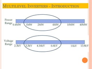
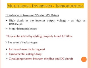
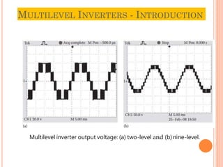
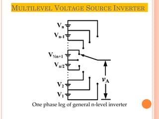
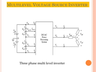
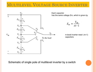
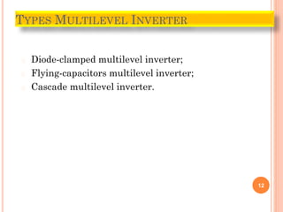
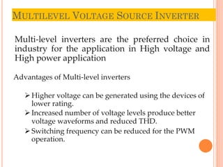
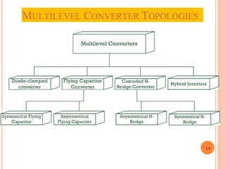
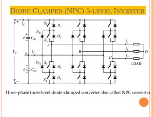
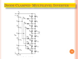
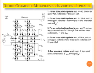
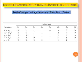
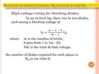
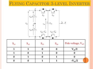
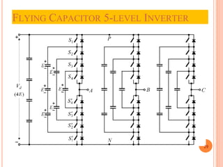
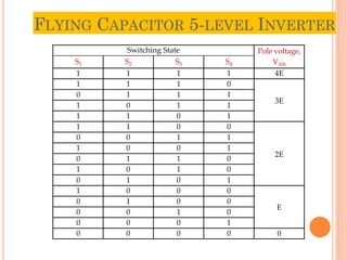
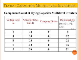
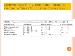
3. MULTILEVEL INVERTERS - INTRODUCTION
3
Drawbacks of two-level VSIs for MV Drives
High dv/dt in the inverter output voltage – as high as
10,000V/µs
Motor harmonic losses
This can be solved by adding properly tuned LC filter.
It has some disadvantages
Increased manufacturing cost
Fundamental voltage drop
Circulating current between the filter and DC circuit
7. MULTILEVEL VOLTAGE SOURCE INVERTER
7
Schematic of single pole of multilevel inverter by a switch
Each capacitor
has the same voltage Em, which is given by
m level inverter need (m-1)
capacitors
8. MULTILEVEL VOLTAGE SOURCE INVERTER
8
The actual realization of the switch requires
bidirectional switching devices
for each node. The topological structure of
multilevel inverter must
(1) have less switching devices as far as possible,
(2) be capable of withstanding very high input
voltage for high-power applications,
(3) have lower switching frequency for each
switching device.
10. MULTILEVEL VOLTAGE SOURCE INVERTER
10
The general structure of the multilevel converter is to synthesize a
near sinusoidal voltage from several levels of dc voltages, typically
obtained from capacitor voltage sources.
As the number of levels increases, the synthesized output waveform
has
more steps, which produce a staircase wave that approaches a
desired waveform.
Also, as more steps are added to the waveform, the harmonic
distortion of the output wave decreases, approaching zero as the
number of levels increases.
As the number of levels increases, the voltage that can be spanned
by summing multiple voltage levels also increases.
11. MULTILEVEL VOLTAGE SOURCE INVERTER
11
The output voltage during the positive half-cycle can found from
where SFn is the switching or control function of nth node and it takes a value of 0
or 1. Generally, the capacitor terminal voltages E1, E2, call have the same value Em.
13. MULTILEVEL VOLTAGE SOURCE INVERTER
13
Multi-level inverters are the preferred choice in
industry for the application in High voltage and
High power application
Advantages of Multi-level inverters
Higher voltage can be generated using the devices of
lower rating.
Increased number of voltage levels produce better
voltage waveforms and reduced THD.
Switching frequency can be reduced for the PWM
operation.
17. 17
DIODE CLAMPED MULTILEVEL INVERTER -1 PHASE
1. For an output voltage level vao = Vdc, turn on all
upper-half switches Sa1 through Sa4.
2. For an output voltage level vao = 3Vdc/4, turn on
three upper switches Sa2 through Sa4 and one lower
switch Sa1
‘
3. For an output voltage level v ao = Vdc/2, turn on
two upper switches Sa3 through Sa4 and two lower
switches Sa1 ‘ and Sa2’
4. For an output voltage level vao = Vdc/4, turn on
one upper switch Sa4 and three lower switches Sa1
through Sa3
5. For an output voltage level vao = 0, turn on all
lower half switches S ‘a1 , through Sa4’
19. � High-voltage rating for blocking diodes:
In an m-level leg, there can be two diodes,
each seeing a blocking voltage of
19
FEATURES OF DIODE CLAMPED MULTILEVEL INVERTER
where m is the number of levels;
k goes from 1 to 1m - 22;
Vdc is the total dc-link voltage.
the number of diodes required for each phase is
ND as (m-1)(m-2)
20. � High-voltage rating for blocking diodes:
� Capacitor voltage unbalance:
20
FEATURES OF DIODE CLAMPED MULTILEVEL INVERTER
21. Major advantages of the diode-clamped inverter
•When the number of levels is high enough, the
harmonic content is low enough to avoid the
need for filters.
• Inverter efficiency is high because all devices
are switched at the fundamental frequency.
• The control method is simple.
22. Major Disadvantages of the diode-clamped inverter
• Excessive clamping diodes are required when
the number of levels is high.
• It is difficult to control the real power flow of the
individual converter in multi converter systems.
24. DIODE CLAMPED (NPC) 4-LEVEL AND 5-
level Inverters
SWITCH STATUS
VAN
FOUR-LEVEL INVERTER
S1 S2 S3 S1’ S2’ S3’
1 1 1 0 0 0 3E
0 1 1 1 0 0 2E
0 0 1 1 1 0 E
0 0 0 1 1 1 0
FIVE-LEVEL INVERTER
VAN
S1 S2 S3 S4 S1’ S2’ S3’ S4’
1 1 1 1 0 0 0 0 4E
0 1 1 1 1 0 0 0 3E
0 0 1 1 1 1 0 0 2E
0 0 0 1 1 1 1 0 E
0 0 0 0 1 1 1 1 0
24
25. DIODE CLAMPED (NPC) MULTILEVEL
INVERTERS
Component Count of Diode-Clamped Multilevel Inverters
Voltage Level
m
Active Switches
6(m-1)
Clamping Diodesa
3(m-1)(m-2)
DC Capacitors
(m-1)
3 12 6 2
4 18 18 3
5 24 36 4
6 30 60 5
7 36 90 6
aAll diodes and active switches have the same voltage rating.
25
26. DIODE CLAMPED (NPC) MULTILEVEL
INVERTERS
26
Disadvantages
Uneven loss distribution in the devices
In a fundamental cycle, the conduction period of the
inner devices is more than the outer devices. This
causes unequal losses in devices in a leg.
The fluctuation of the dc bus midpoint
voltage
Additional clamping diodes.
Complicated PWM switching pattern design
33. THE MAJOR ADVANTAGES OF THE FLYING-CAPACITORS
INVERTER CAN BE SUMMARIZED AS FOLLOWS
� Large amounts of storage capacitors can provide
capabilities during power outages.
� These inverters provide switch combination
redundancy for balancing different voltage levels.
� Like the diode-clamp inverter with more levels, the
harmonic content is low enough to avoid the need for
filters.
� Both real and reactive power flow can be controlled.
33
34. THE MAJOR DISADVANTAGES OF THE FLYING-CAPACITORS
INVERTER CAN BE SUMMARIZED AS FOLLOWS:
� An excessive number of storage capacitors is required
when the number of levels is high. High-level
inverters are more difficult to package with the bulky
power capacitors and are more expensive too.
� The inverter control can be very complicated, and the
switching frequency and switching losses are high for
real power transmission.
34
38. MULTILEVEL (5-LEVEL) CASCADED H-BRIDGE
INVERTERS - WITH EQUAL VOLTAGES
PEGCRES
2015
38
Switching State
VH1 VH2
Pole voltage,
VAN
S11 S31 S12 S32
1 0 1 0 E E 2E
1 0 1 1 E 0
E
1 0 0 0 E 0
1 1 1 0 0 E
0 0 1 0 0 E
0 0 0 0 0 0
0
0 0 1 1 0 0
1 1 1 1 0 0
1 1 0 0 0 0
1 0 0 1 E -E
0 1 1 0 -E E
0 1 1 1 -E 0
-E
0 1 0 0 -E 0
1 1 0 1 0 -E
0 0 0 1 0 -E
0 1 0 1 -E -E -2E
39. MULTILEVEL CASCADED H-BRIDGE
INVERTERS – WITH EQUAL VOLTAGES
39
The number of voltage levels in a CHB inverter can
be found from
m = (2H + 1)
where H is the number of H-bridge cells per phase leg.
The voltage level m is always an odd number for the CHB
inverter while in other multilevel topologies such as
diode-clamped inverters, it can be either an even or odd
number.
The total number of active switches (IGBTs) used in
the CHB inverters can be calculated by
Nsw = 6(m – 1)
42. MULTILEVEL CASCADED H-BRIDGE INVERTERS -
WITH UNEQUAL VOLTAGES
Voltage Level and Switching State of the Two-Cell Seven-Level CHB
Inverter with Unequal dc Voltages
42
43. CASCADED H-BRIDGE MULTILEVEL INVERTERS
Component Count of Cascaded H-Bridge Multilevel Inverters
Voltage Level
m
Active Switches
6(m-1)
Clamping Diodes DC Sources
3 12 0 3
5 24 0 6
7 36 0 9
9 48 0 12
43
44. FEATURES OF CASCADED INVERTER
� For real power conversions from ac to dc and then dc
to ac, the cascaded inverters need separate dc
sources. The structure of separate dc sources is well
suited for various renewable energy sources such as
fuel cell, photovoltaic, and biomass.
� Connecting dc sources between two converters in a
back-to-back fashion is not possible because a short
circuit can be introduced when two back-to-back
converters are not switching synchronously.
44
45. 45
The major advantages of the cascaded inverter
can be summarized as follows:
• Compared with the diode-clamped and flying-
capacitors inverters, it requires the least number
of components to achieve the same number of
voltage levels.
• Optimized circuit layout and packaging are
possible because each level has the same
structure and there are no extra clamping diodes
or voltage-balancing capacitors.
• Soft-switching techniques can be used to
reduce switching losses and device stresses.
46. 46
The major disadvantage of the
cascaded inverter is as follows:
• It needs separate dc sources for
real power conversions, thereby
limiting its applications.
47. KEY FEATURES OF A MULTILEVEL STRUCTURE
� The output voltage and power increase with number of
levels. Adding a voltage level involves adding a main
switching device to each phase.
� The harmonic content decreases as the number of levels
increases and filtering requirements are reduced.
� With additional voltage levels, the voltage waveform has
more free-switching angles, which can be preselected for
harmonic elimination.
� In the absence of any PWM techniques, the switching
losses can be avoided.
� Increasing output voltage and power does not require an
increase in rating of individual device.
47
49. REFERENCES
49
B. Wu, High-Power Converters and AC Drives, Wiley-IEEE
Press, Piscataway, NJ, 2006.
J. Rodriguez, J. S. Lai, and F. Z. Peng, Multilevel inverters: A
survey of topologies, controls, and applications, IEEE
Transactions on Industrial Electronics, 49(4), 724–738, August
2002.
N. Mohan,
Electronics:
T. M. Undeland, and W. P. Robbins, Power
Converters, Applications, and Design, 3 edn,
Wiley, Hoboken, NJ, October 10, 2002.
Rodriguez, S. Bernet, B. Wu, J. O. Pontt, and S. Kouro,
Multilevel voltage-source-converter topologies for industrial
medium-voltage drives, IEEE Transactions on Industrial
Electronics, 54(6), 2930–2945, December 2007.