Downloaded 12 times

![Experimental Investigation of Electrode Wear in Die-Sinking EDM………….
| IJMER | ISSN: 2249–6645 | www.ijmer.com | Vol. 5 | Iss.3| Mar. 2015 | 54|
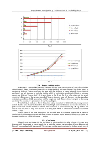
cylindrical copper electrode. It has been also investigated that electrode wear in the form of length (mm)
decreases with the increasing in Time-on and Time-off when current is constant. From this experimental
investigation it has been concluded that cylindrical copper electrode can be used for long time without
redressing the electrode. Due to less wear die-sinking EDM will provide an economic advantage for making
different holes and cavities.
REFERENCES
[1] Bergaley, Ajeet., Sharma, Narendra. (2013), “Optimization Of Electrical And Non Electrical Factor In Edm For
Machining Die Steel Using Copper Electrode By Adopting Taghuchi Technique” International Journal of Innovative
Technology And Exploraing Engineering , Vol. 3, Issue 3, Pp44-48, Issn:2278-3075.
[2] Choudhary, Rajesh., Kumar, H and Garg, R. K. (2010), “Analysis And Evaluation Of Heat Affected Zones In
Electric Discharge Machining Of En-31 Die Steel” Indian Journal Of Engineering & Material Science, Vol. 17,
Pp91-98.
[3] Daneshmand, Saeed., Kahrizi, Ehsan Farahmand., Abedi,Esmail and Abdolhosseni, M. Mir. (2013), “Influence Of
Machining Parameters On Electro Discharge Machining Of Ni-Ti Shape Memory Alloys” International Journal Of
Electrochemical Science, Pp.3095-3104.
[4] Gao, Quing., Zhang, Quin-He., Su, Shu-Peng and Zhang, Jian-Hua. (2008), “Parameter Optimization Model In
Electrical Discharge Machining Process” Journal Of Zhejiang University Science A, Issn:1673-565x (Print),
Issn:1862-1775 (Online), 9(1), Pp.104-108.
[5] Gopalkannan, Subramanian and Senthilvelan, Thiagarajan. (2012), “Effect Of Electrode Material On Electrode
Discharge Machining Of 316 L And 17-4 Ph Stainless Steels” Journal Of Minerals And Materials Characterization
And Engineering, Pp. 685-690.
[6] Jameson, Elman C. (2001), “Electrical Discharge Machining” Society Of Manufacturing Engineers,
ISBN:087263521x, 9780872635210, Pp.1-329, Technology & Engineering, Manufacturing.
[7] http://mechtorrent.blogspot.in, “Electrical Discharge Machining” Mech Torrent, Issue June, 14, 2013.](https://image.slidesharecdn.com/h050302-4954-150418060354-conversion-gate01/85/Experimental-Investigation-of-Electrode-Wear-in-Die-Sinking-EDM-on-Different-Pulse-on-off-Time-s-in-Cylindrical-Copper-Electrode-6-320.jpg)

This document summarizes an experimental investigation of electrode wear in die-sinking electrical discharge machining (EDM) using different pulse-on and pulse-off times. The study examined electrode wear in cylindrical copper electrodes machining die-steel workpieces. Electrode wear was measured by weight loss and length reduction of the copper electrodes under different pulse-on, pulse-off times and constant current. The results showed that electrode wear decreased with increasing pulse-on and pulse-off times, and was minimized at a pulse-on time of 200 microseconds and pulse-off time of 30 microseconds at 12 amperes of current. The study concluded that optimizing pulse-on, pulse-off times can reduce electrode wear and improve the