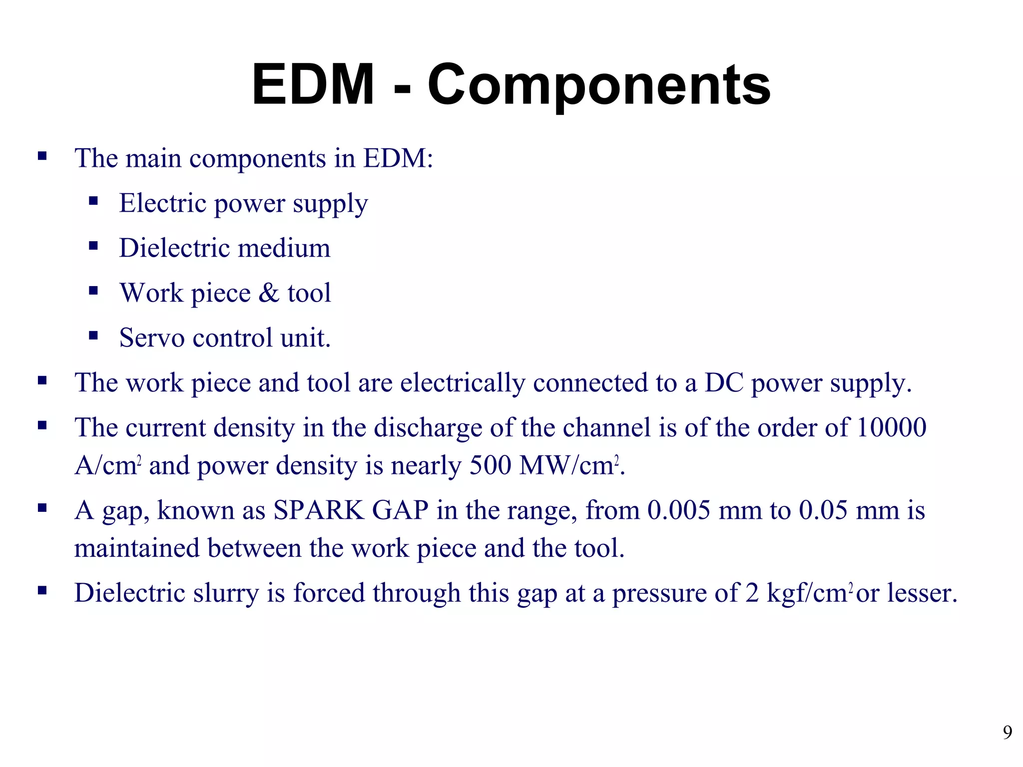
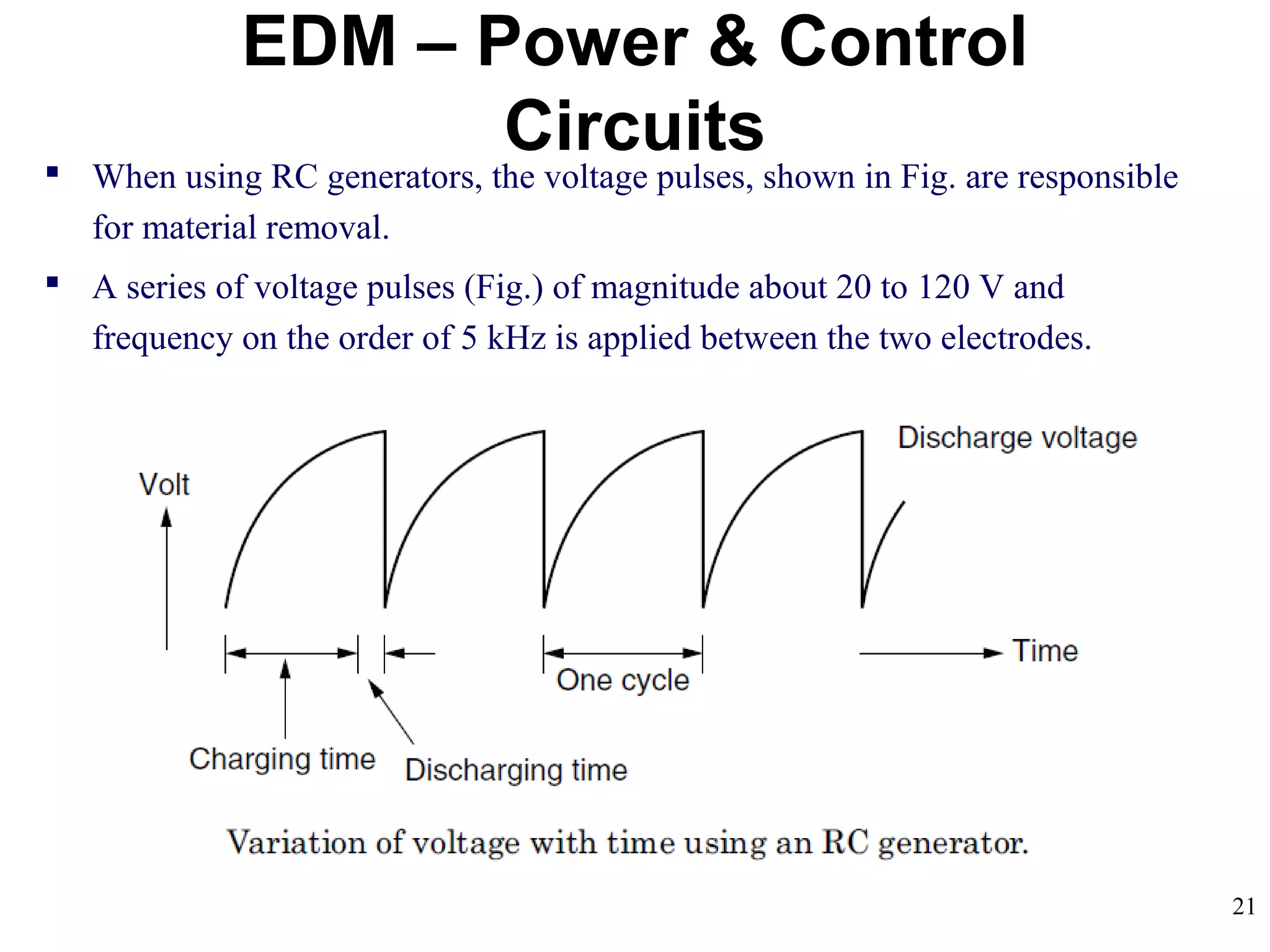
Here you are watching PowerPoint Presentation of EDM (Electrical Machining Process). It is a kind of unconventional machining process.Thanks for watching.
Electro Discharge Machining
Introduction
Process
Process Parameters
Dielectric
Advantages of EDM
APPLICATIONS
Power generator
Wire EDM
ELECTRIC DISCHARGE GRINDING (EDG)
Electro Discharge Machining
Introduction
Process
Process Parameters
Dielectric
Advantages of EDM
APPLICATIONS
Power generator
Wire EDM
ELECTRIC DISCHARGE GRINDING (EDG)
ELECTROCHEMICAL MACHINING - NON TRADITIONAL MACHININGSajal Tiwari
Non-conventional machining system in which metal is removed by an electrochemical process. Characterized as ‘Reverse Electroplating’ means it removes metal instead of adding it. Normally used for mass production and for hard materials that are difficult to machine using conventional processes. Both external and internal geometries can be machined.
Working of Laser beam machining process. Its one kind of non traditional or advanced manufacturing process.Production of laser beam and with the use of lasers how can material can be removed is to be explained over here...
In today's manufacturing industry. various manufacturing operations have been widely used for producing products for many industrial sectors.
The electroerosion-dissolution machining (EEDM) is a combination of pulsating electroerosion action aided by electrochemical dissolution.
EEDM (also called ECDM or ECAM) is a new development, which combines features of both ECD and EDE. It utilizes electrical dis- charges in electrolytes for material removal. Such a combination allows high metal removal rates to be achieved
The EEDM process is a further development of pulsed electrochemical machining (PECM) where, at high input power, phenomena that limit further dissolution may arise. Under such circumstances, the machining medium changes to a gas- vapour mixture that interferes with the ion transfer in the electric field.
In hybrid thermal machining; the major material removal mechanism is a thermal one which normally leads to melting and evaporation of the workpiece material
Thermal machining can be assisted using electro- chemical dissolution (ECD) and/or mechanical abrasion (MA). This combination leads to high removal rates and improved product quality.
The main machining phases and process components of EEDM. According to Fig. , spark discharges occur at random locations across the machining gap while electrolysis is believed to be localized in the proximity of the pits of the formed craters which are soon made smooth, probably as a result of the high temperature of the metal and electrolyte. The EEDM material removal rate is enhanced by the sparking action and not by the arcing one because the latter usually results in a low and localized material removal rate and yields more irregular machined surfaces.
Advantages
EEDM can produce significantly smoother surfaces due to the presence of high-rate ECD.
The depth of the heat-affected layer can be significantly reduced or eliminated.
High machining rates are also possible thereby increasing the productivity and reducing the unit production cost.
The erosion of tool electrodes is reduced by a factor of 4 to 5 percent compared to that of pure EDM.
Burrs at the edges are particularly absent due to the existence of the ECD phase.
Electrical Discharge Machine is an advanced machining method which removes metal by a series of recurring electrical discharges betweenn an electrode and a conductive workpiece, submerged in a dielectric fluid.
Current Advanced Research Development of Electric Discharge Machining (EDM): ...sushil Choudhary
Electrical discharge machining (EDM) process is one of the most commonly used nonconventional
precise material removal processes. Electrical discharge machining (EDM) is a process for
shaping hard metals and forming deep complex shaped holes by arc erosion in all kinds of electroconductive
materials. Erosion pulse discharge occurs in a small gap between the work piece and the
electrode. This removes the unwanted material from the parent metal through melting and vaporizing in
presence of dielectric fluid. In recent years, EDM researchers have explored a number of ways to improve
EDM Process parameters such as Electrical parameters, Non-Electrical Parameters, tool Electrode based
parameters & Powder based parameters. This new research shares the same objectives of achieving more
efficient metal removal rate reduction in tool wear and improved surface quality. This paper reviews the
research work carried out from the inception to the development of die-sinking EDM, Water in EDM, dry
EDM, and Powder mixed electric Discharge Machining. Within the past decade. & also briefly describing the Current Research technique Trend in EDM, future EDM research direction.
The International Journal of Engineering & Science is aimed at providing a platform for researchers, engineers, scientists, or educators to publish their original research results, to exchange new ideas, to disseminate information in innovative designs, engineering experiences and technological skills. It is also the Journal's objective to promote engineering and technology education. All papers submitted to the Journal will be blind peer-reviewed. Only original articles will be published.
The papers for publication in The International Journal of Engineering& Science are selected through rigorous peer reviews to ensure originality, timeliness, relevance, and readability.
Experimental Investigation of Electrode Wear in Die-Sinking EDM on Different ...IJMER
EDM is an advanced machining method for manufacturing, hard material parts which
are difficult to machine by conventional machining process. There are various type of products which
can be produced by using Die-sinking EDM, such as dies, moulds. Parts of aerospace, automobile
industry and surgical components can be finished machined by EDM. In present scenario numbers of
researchers have explored a number of ways to improve EDM efficiency. The optimum selection of
manufacturing condition is very important in manufacturing processes as they determine surface
quality, dimensional accuracy of the obtained parts. This experimental investigation is mainly focused
on electrode wear in cylindrical copper electrode on different pulse-on & off time (µs) at constant
current(amp.) which is an important parameter. In this experimental work, an investigation has been
made to optimize the response parameter (electrode wear) of EDM on die-steel with electrolytic
cylindrical copper electrode. Die-steel (HRC-58) is widely used in production of dies. In this
investigation copper has been taken as electrode and die-steel as a work piece. Electrode wear has
been investigated in the form of weight (gm) and length (mm.) of electrode on different input process
parameters. viz constant discharge current (amp.), pulse on time (T-on), pulse off time (T-off)
KuberTENes Birthday Bash Guadalajara - K8sGPT first impressionsVictor Morales
K8sGPT is a tool that analyzes and diagnoses Kubernetes clusters. This presentation was used to share the requirements and dependencies to deploy K8sGPT in a local environment.
Sachpazis:Terzaghi Bearing Capacity Estimation in simple terms with Calculati...Dr.Costas Sachpazis
Terzaghi's soil bearing capacity theory, developed by Karl Terzaghi, is a fundamental principle in geotechnical engineering used to determine the bearing capacity of shallow foundations. This theory provides a method to calculate the ultimate bearing capacity of soil, which is the maximum load per unit area that the soil can support without undergoing shear failure. The Calculation HTML Code included.
Online aptitude test management system project report.pdfKamal Acharya
The purpose of on-line aptitude test system is to take online test in an efficient manner and no time wasting for checking the paper. The main objective of on-line aptitude test system is to efficiently evaluate the candidate thoroughly through a fully automated system that not only saves lot of time but also gives fast results. For students they give papers according to their convenience and time and there is no need of using extra thing like paper, pen etc. This can be used in educational institutions as well as in corporate world. Can be used anywhere any time as it is a web based application (user Location doesn’t matter). No restriction that examiner has to be present when the candidate takes the test.
Every time when lecturers/professors need to conduct examinations they have to sit down think about the questions and then create a whole new set of questions for each and every exam. In some cases the professor may want to give an open book online exam that is the student can take the exam any time anywhere, but the student might have to answer the questions in a limited time period. The professor may want to change the sequence of questions for every student. The problem that a student has is whenever a date for the exam is declared the student has to take it and there is no way he can take it at some other time. This project will create an interface for the examiner to create and store questions in a repository. It will also create an interface for the student to take examinations at his convenience and the questions and/or exams may be timed. Thereby creating an application which can be used by examiners and examinee’s simultaneously.
Examination System is very useful for Teachers/Professors. As in the teaching profession, you are responsible for writing question papers. In the conventional method, you write the question paper on paper, keep question papers separate from answers and all this information you have to keep in a locker to avoid unauthorized access. Using the Examination System you can create a question paper and everything will be written to a single exam file in encrypted format. You can set the General and Administrator password to avoid unauthorized access to your question paper. Every time you start the examination, the program shuffles all the questions and selects them randomly from the database, which reduces the chances of memorizing the questions.
Student information management system project report ii.pdfKamal Acharya
Our project explains about the student management. This project mainly explains the various actions related to student details. This project shows some ease in adding, editing and deleting the student details. It also provides a less time consuming process for viewing, adding, editing and deleting the marks of the students.
Hierarchical Digital Twin of a Naval Power SystemKerry Sado
A hierarchical digital twin of a Naval DC power system has been developed and experimentally verified. Similar to other state-of-the-art digital twins, this technology creates a digital replica of the physical system executed in real-time or faster, which can modify hardware controls. However, its advantage stems from distributing computational efforts by utilizing a hierarchical structure composed of lower-level digital twin blocks and a higher-level system digital twin. Each digital twin block is associated with a physical subsystem of the hardware and communicates with a singular system digital twin, which creates a system-level response. By extracting information from each level of the hierarchy, power system controls of the hardware were reconfigured autonomously. This hierarchical digital twin development offers several advantages over other digital twins, particularly in the field of naval power systems. The hierarchical structure allows for greater computational efficiency and scalability while the ability to autonomously reconfigure hardware controls offers increased flexibility and responsiveness. The hierarchical decomposition and models utilized were well aligned with the physical twin, as indicated by the maximum deviations between the developed digital twin hierarchy and the hardware.
6th International Conference on Machine Learning & Applications (CMLA 2024)ClaraZara1
6th International Conference on Machine Learning & Applications (CMLA 2024) will provide an excellent international forum for sharing knowledge and results in theory, methodology and applications of on Machine Learning & Applications.
Water billing management system project report.pdfKamal Acharya
Our project entitled “Water Billing Management System” aims is to generate Water bill with all the charges and penalty. Manual system that is employed is extremely laborious and quite inadequate. It only makes the process more difficult and hard.
The aim of our project is to develop a system that is meant to partially computerize the work performed in the Water Board like generating monthly Water bill, record of consuming unit of water, store record of the customer and previous unpaid record.
We used HTML/PHP as front end and MYSQL as back end for developing our project. HTML is primarily a visual design environment. We can create a android application by designing the form and that make up the user interface. Adding android application code to the form and the objects such as buttons and text boxes on them and adding any required support code in additional modular.
MySQL is free open source database that facilitates the effective management of the databases by connecting them to the software. It is a stable ,reliable and the powerful solution with the advanced features and advantages which are as follows: Data Security.MySQL is free open source database that facilitates the effective management of the databases by connecting them to the software.
Harnessing WebAssembly for Real-time Stateless Streaming PipelinesChristina Lin
Traditionally, dealing with real-time data pipelines has involved significant overhead, even for straightforward tasks like data transformation or masking. However, in this talk, we’ll venture into the dynamic realm of WebAssembly (WASM) and discover how it can revolutionize the creation of stateless streaming pipelines within a Kafka (Redpanda) broker. These pipelines are adept at managing low-latency, high-data-volume scenarios.
2. 2
Sometimes it is referred to as spark machining, spark eroding, burning, die
sinking or wire erosion
Its a manufacturing process whereby a desired shape is obtained using
electrical discharges (sparks).
Material is removed from the workpiece by a series of rapidly recurring
current discharges between two electrodes, separated by a dielectric liquid and
subject to an electric voltage.
One of the electrodes – ‘tool-electrode’ or ‘tool’ or ‘electrode’.
Other electrode - workpiece-electrode or ‘workpiece’.
As distance between the two electrodes is reduced, the current intensity
becomes greater than the strength of the dielectric (at least in some points)
causing it to break.
Introduction
3. 3
This allows current to flow between the two electrodes.
This phenomenon is the same as the breakdown of a capacitor.
As a result, material is removed from both the electrodes.
Once the current flow stops, new liquid dielectric is usually conveyed into the
electrode zone enabling the solid particles (debris) to be carried away.
Adding new liquid dielectric in the electrode volume is commonly referred to
as flushing.
Also, after a current flow, a difference of potential between the two electrodes
is restored to what it was before the breakdown, so that a new liquid dielectric
breakdown can occur.
History
4. 4
In 1770, English Physicist Joseph Priestley studied the erosive effect of
electrical discharges.
Furthering Priestley's research, the EDM process was invented by two Russian
scientists, Dr. B.R. Lazarenko and Dr. N.I. Lazarenko in 1943.
In their efforts to exploit the destructive effects of an electrical discharge, they
developed a controlled process for machining of metals.
Their initial process used a spark machining process, named after the
succession of sparks (electrical discharges) that took place between two
electrical conductors immersed in a dielectric fluid.
The discharge generator effect used by this machine, known as the Lazarenko
Circuit, was used for many years in the construction of generators for electrical
discharge.
History
5. 5
New researchers entered the field and contributed many fundamental
characteristics of the machining method we know today.
In 1952, the manufacturer Charmilles created the first machine using the spark
machining process and was presented for the first time at the European
Machine Tool Exhibition in 1955.
In 1969, Agie launched the world's first numerically controlled wire-cut EDM
machine.
Seibu developed the first CNC wire EDM machine in 1972 and the first system
was manufactured in Japan.
Recently, the machining speed has gone up by 20 times.
This has decreased machining costs by at least 30 percent and improved the
surface finish by a factor of 1.5
History
6. 6
EDM is a machining method primarily used for hard metals or those that
would be very difficult to machine with traditional techniques.
EDM typically works with materials that are electrically conductive, although
methods for machining insulating ceramics with EDM have been proposed.
EDM can cut intricate contours or cavities in hardened steel without the need
for heat treatment to soften and re-harden them.
This method can be used with any other metal or metal alloy such as titanium,
hastelloy, kovar, and inconel.
Also, applications of this process to shape polycrystalline diamond tools have
been reported.
General Aspects of EDM
9. 9
The main components in EDM:
Electric power supply
Dielectric medium
Work piece & tool
Servo control unit.
The work piece and tool are electrically connected to a DC power supply.
The current density in the discharge of the channel is of the order of 10000
A/cm2
and power density is nearly 500 MW/cm2
.
A gap, known as SPARK GAP in the range, from 0.005 mm to 0.05 mm is
maintained between the work piece and the tool.
Dielectric slurry is forced through this gap at a pressure of 2 kgf/cm2
or lesser.
EDM - Components
10. 10
It is a process of metal removal based on the principle of material removal by an
interrupted electric spark discharge between the electrode tool and the work
piece.
In EDM, a potential difference is applied between the tool and workpiece.
Essential - Both tool and work material are to be conductors.
The tool and work material are immersed in a dielectric medium.
Generally kerosene or deionised water is used as the dielectric medium.
A gap is maintained between the tool and the workpiece.
Depending upon the applied potential difference (50 to 450 V) and the gap
between the tool and workpiece, an electric field would be established.
Generally the tool is connected to the negative terminal (cathode) of the
generator and the workpiece is connected to positive terminal (anode).
EDM – Working Principle
11. 11
As the electric field is established between the tool and the job, the free
electrons on the tool are subjected to electrostatic forces.
If the bonding energy of the electrons is less, electrons would be emitted from
the tool.
Such emission of electrons are called or termed as ‘cold emission’.
The “cold emitted” electrons are then accelerated towards the job through the
dielectric medium.
As they gain velocity and energy, and start moving towards the job, there
would be collisions between the electrons and dielectric molecules.
Such collision may result in ionization of the dielectric molecule.
Ionization depends on the ionization energy of the dielectric molecule and the
energy of the electron.
EDM – Working Principle
12. 12
As the electrons get accelerated, more positive ions and electrons would get
generated due to collisions.
This cyclic process would increase the concentration of electrons and ions in
the dielectric medium between the tool and the job at the spark gap.
The concentration would be so high that the matter existing in that channel
could be characterised as “plasma”.
The electrical resistance of such plasma channel would be very less.
Thus all of a sudden, a large number of electrons will flow from tool to job and
ions from job to tool.
This is called avalanche motion of electrons.
Such movement of electrons and ions can be visually seen as a spark.
Thus the electrical energy is dissipated as the thermal energy of the spark.
EDM – Working Principle
13. 13
The high speed electrons then impinge on the job and ions on the tool.
The kinetic energy of the electrons and ions on impact with the surface of the
job and tool respectively would be converted into thermal energy or heat flux.
Such intense localized heat flux leads to extreme instantaneous confined rise in
temperature which would be in excess of 10,000o
C.
Such localized extreme rise in temperature leads to material removal.
Material removal occurs due to instant vaporization of the material as well as
due to melting.
The molten metal is not removed completely but only partially.
EDM – Working Principle
14. 14
Upon withdrawal of potential difference, plasma channel collapses.
This ultimately creates compression shock waves on both the electrode surface.
Particularly at high spots on work piece surface, which are closest to the tool.
This evacuates molten material and forms a crater around the site of the spark.
The whole sequence of operation occurs within a few microseconds.
EDM – Working Principle
16. 16
Thus to summarise, the material removal in EDM mainly occurs due to
formation of shock waves as the plasma channel collapse owing to
discontinuation of applied potential difference
Generally the workpiece is made positive and the tool negative.
Hence, the electrons strike the job leading to crater formation due to high
temperature and melting and material removal.
Similarly, the positive ions impinge on the tool leading to tool wear.
In EDM, the generator is used to apply voltage pulses between the tool and
job.
A constant voltage is not applied. Only sparking is desired rather than arcing.
Arcing leads to localized material removal at a particular point whereas sparks
get distributed all over the tool surface leading to uniform material removal.
EDM – Working Principle
18. 18
EDM – Power & Control
Circuits
Two broad categories of generators (power supplies) are in use on EDM.
Commercially available: RC circuits based and transistor controlled pulses.
In the first category, the main parameters to choose from at setup time are the
resistance(s) of the resistor(s) and the capacitance(s) of the capacitor(s).
In an ideal condition, these quantities would affect the maximum current
delivered in a discharge.
Current delivery in a discharge is associated with the charge accumulated on the
capacitors at a certain moment.
Little control is expected over the time of discharge, which is likely to depend
on the actual spark-gap conditions.
Advantage: RC circuit generator can allow the use of short discharge time more
easily than the pulse-controlled generator.
19. 19
EDM – Power & Control
Circuits
Also, the open circuit voltage (i.e. voltage between electrodes when dielectric
is not broken) can be identified as steady state voltage of the RC circuit.
In generators based on transistor control, the user is usually able to deliver a
train of voltage pulses to the electrodes.
Each pulse can be controlled in shape, for instance, quasi-rectangular.
In particular, the time between two consecutive pulses and the duration of each
pulse can be set.
The amplitude of each pulse constitutes the open circuit voltage.
Thus, maximum duration of discharge is equal to duration of a voltage pulse.
Maximum current during a discharge that the generator delivers can also be
controlled.
20. 20
EDM – Power & Control
Circuits Details of generators and control systems on EDMs are not always easily
available to their user.
This is a barrier to describing the technological parameters of EDM process.
Moreover, the parameters affecting the phenomena occurring between tool and
electrode are also related to the motion controller of the electrodes.
A framework to define and measure the electrical parameters during an EDM
operation directly on inter-electrode volume with an oscilloscope external to
the machine has been recently proposed by Ferri et al.
This would enable the user to estimate directly the electrical parameter that
affect their operations without relying upon machine manufacturer's claims.
When machining different materials in the same setup conditions, the actual
electrical parameters are significantly different.
21. 21
EDM – Power & Control
Circuits When using RC generators, the voltage pulses, shown in Fig. are responsible
for material removal.
A series of voltage pulses (Fig.) of magnitude about 20 to 120 V and
frequency on the order of 5 kHz is applied between the two electrodes.
25. 25
EDM – Electrode Material
Electrode material should be such that it would not undergo much tool wear
when it is impinged by positive ions.
Thus the localised temperature rise has to be less by properly choosing its
properties or even when temperature increases, there would be less melting.
Further, the tool should be easily workable as intricate shaped geometric
features are machined in EDM.
Thus the basic characteristics of electrode materials are:
High electrical conductivity – electrons are cold emitted more easily and
there is less bulk electrical heating
High thermal conductivity – for the same heat load, the local temperature
rise would be less due to faster heat conducted to the bulk of the tool and
thus less tool wear.
26. 26
EDM – Electrode Material
Higher density – for less tool wear and thus less dimensional loss or
inaccuracy of tool
High melting point – high melting point leads to less tool wear due to less
tool material melting for the same heat load
Easy manufacturability
Cost – cheap
The followings are the different electrode materials which are used commonly
in the industry:
Graphite
Electrolytic oxygen free copper
Tellurium copper – 99% Cu + 0.5% tellurium
Brass
27. 27
EDM – Electrode Material
Graphite (most common) - has fair wear characteristics, easily machinable.
Small flush holes can be drilled into graphite electrodes.
Copper has good EDM wear and better conductivity.
It is generally used for better finishes in the range of Ra = 0.5 μm.
Copper tungsten and silver tungsten are used for making deep slots under poor
flushing conditions especially in tungsten carbides.
It offers high machining rates as well as low electrode wear.
Copper graphite is good for cross-sectional electrodes.
It has better electrical conductivity than graphite while the corner wear is higher.
Brass ensures stable sparking conditions and is normally used for specialized
applications such as drilling of small holes where the high electrode wear is
acceptable.
28. 28
EDM – Electrode Movement
In addition to the servo-controlled feed, the tool electrode may have an
additional rotary or orbiting motion.
Electrode rotation helps to solve the flushing difficulty encountered when
machining small holes with EDM.
In addition to the increase in cutting speed, the quality of the hole produced is
superior to that obtained using a stationary electrode.
Electrode orbiting produces cavities having the shape of the electrode.
The size of the electrode and the radius of the orbit (2.54 mm maximum)
determine the size of the cavities.
Electrode orbiting improves flushing by creating a pumping effect of the
dielectric liquid through the gap.
30. 30
EDM – Electrode Wear
The melting point is the most important factor in determining the tool wear.
Electrode wear ratios are expressed as end wear, side wear, corner wear, and
volume wear.
“No wear EDM” - when the electrode-to-workpiece wear ratio is 1 % or less.
Electrode wear depends on a number of factors associated with the EDM, like
voltage, current, electrode material, and polarity.
The change in shape of the tool electrode due to the electrode wear causes
defects in the workpiece shape.
Electrode wear has even more pronounced effects when it comes to
micromachining applications.
The corner wear ratio depends on the type of electrode.
The low melting point of aluminum is associated with the highest wear ratio.
32. 32
EDM – Electrode Wear
Graphite has shown a low tendency to wear and has the possibility of being
molded or machined into complicated electrode shapes.
The wear rate of the electrode tool material (Wt) and the wear ratio (Rw) are
given by Kalpakjian (1997).
33. 33
EDM – Dielectric
In EDM, material removal mainly occurs due to thermal evaporation and
melting.
As thermal processing is required to be carried out in absence of oxygen so
that the process can be controlled and oxidation avoided.
Oxidation often leads to poor surface conductivity (electrical) of the workpiece
hindering further machining.
Hence, dielectric fluid should provide an oxygen free machining environment.
Further it should have enough strong dielectric resistance so that it does not
breakdown electrically too easily.
But at the same time, it should ionize when electrons collide with its molecule.
Moreover, during sparking it should be thermally resistant as well.
Generally kerosene and deionised water is used as dielectric fluid in EDM.
34. 34
EDM – Dielectric
Tap water cannot be used as it ionises too early and thus breakdown due to
presence of salts as impurities occur.
Dielectric medium is generally flushed around the spark zone.
It is also applied through the tool to achieve efficient removal of molten
material.
Three important functions of a dielectric medium in EDM:
1. Insulates the gap between the tool and work, thus preventing a spark to
form until the gap voltage are correct.
2. Cools the electrode, workpiece and solidifies the molten metal particles.
3. Flushes the metal particles out of the working gap to maintain ideal
cutting conditions, increase metal removal rate.
It must be filtered and circulated at constant pressure.
35. 35
EDM – Dielectric
The main requirements of the EDM dielectric fluids are adequate viscosity,
high flash point, good oxidation stability, minimum odor, low cost, and good
electrical discharge efficiency.
For most EDM operations kerosene is used with certain additives that prevent
gas bubbles and de-odoring.
Silicon fluids and a mixture of these fluids with petroleum oils have given
excellent results.
Other dielectric fluids with a varying degree of success include aqueous
solutions of ethylene glycol, water in emulsions, and distilled water.
36. 36
EDM – Flushing
One of the important factors in a successful EDM operation is the removal of
debris (chips) from the working gap.
Flushing these particles out of the working gap is very important, to prevent
them from forming bridges that cause short circuits.
EDMs have a built-in power adaptive control system that increases the pulse
spacing as soon as this happens and reduces or shuts off the power supply.
Flushing – process of introducing clean filtered dielectric fluid into spark gap.
If flushing is applied incorrectly, it can result in erratic cutting and poor
machining conditions.
Flushing of dielectric plays a major role in the maintenance of stable
machining and the achievement of close tolerance and high surface quality.
Inadequate flushing can result in arcing, decreased electrode life, and increased
production time.
37. 37
EDM – Flushing
Four methods:
1. Normal flow 2. Reverse flow
3. Jet flushing 4. Immersion flushing
38. 38
EDM – Flushing
Normal flow (Majority)
Dielectric is introduced, under pressure, through one or more passages in
the tool and is forced to flow through the gap between tool and work.
Flushing holes are generally placed in areas where the cuts are deepest.
Normal flow is sometimes undesirable because it produces a tapered
opening in the workpiece.
Reverse flow
Particularly useful in machining deep cavity dies, where the taper
produced using the normal flow mode can be reduced.
The gap is submerged in filtered dielectric, and instead of pressure being
applied at the source a vacuum is used.
With clean fluid flowing between the workpiece and the tool, there is no
side sparking and, therefore, no taper is produced.
39. 39
EDM – Flushing
Jet flushing
In many instances, the desired machining can be achieved by using a
spray or jet of fluid directed against the machining gap.
Machining time is always longer with jet flushing than with the normal
and reverse flow modes.
Immersion flushing
For many shallow cuts or perforations of thin sections, simple immersion
of the discharge gap is sufficient.
Cooling and debris removal can be enhanced during immersion cutting
by providing relative motion between the tool and workpiece.
Vibration or cycle interruption comprises periodic reciprocation of the
tool relative to the workpiece to effect a pumping action of the dielectric.
40. 40
EDM – Flushing
Synchronized, pulsed flushing is also available on some machines.
With this method, flushing occurs only during the non-machining time as
the electrode is retracted slightly to enlarge the gap.
Increased electrode life has been reported with this system.
Innovative techniques such as ultrasonic vibrations coupled with
mechanical pulse EDM, jet flushing with sweeping nozzles, and
electrode pulsing are investigated by Masuzawa (1990).
41. 41
EDM – Flushing
For proper flushing conditions, Metals Handbook (1989) recommends:
1. Flushing through the tool is more preferred than side flushing.
2. Many small flushing holes are better than a few large ones.
3. Steady dielectric flow on the entire workpiece-electrode interface is
desirable.
4. Dead spots created by pressure flushing, from opposite sides of the
workpiece, should be avoided.
5. A vent hole should be provided for any upwardly concave part of the
tool-electrode to prevent accumulation of explosive gases.
6. A flush box is useful if there is a hole in the cavity.
42. 42
EDM – Process Parameters
The waveform is characterized by the:
The open circuit voltage – Vo
The working voltage – Vw
The maximum current – Io
The pulse on time – the duration for which the voltage pulse is applied - ton
The pulse off time – toff
The gap between the workpiece and the tool – spark gap - δ
The polarity – straight polarity – tool (-ve)
The dielectric medium
External flushing through the spark gap.
43. 43
The process parameters - mainly related to the waveform characteristics.
EDM – Process Parameters
44. 44
EDM – Types – Sinker EDM
Sinker EDM, also called cavity type EDM or volume EDM.
Consists of an electrode and workpiece submerged in an insulating liquid such
as oil or other dielectric fluids.
The electrode and workpiece are connected to a suitable power supply.
The power supply generates an electrical potential between the two parts.
As the electrode approaches the workpiece, dielectric breakdown occurs in the
fluid, forming a plasma channel, and a small spark jumps.
These sparks happen in huge numbers at seemingly random locations.
As the base metal is eroded, and the spark gap subsequently increased, the
electrode is lowered automatically so that the process can continue.
Several hundred thousand sparks occur per second, with the actual duty cycle
carefully controlled by the setup parameters.
These controlling cycles are sometimes known as "on time" and "off time“.
45. 45
EDM – Types – Sinker EDM
The on time setting determines the length or duration of the spark.
Hence, a longer on time produces a deeper cavity for that spark and all
subsequent sparks for that cycle.
This creates rougher finish on the workpiece.
The reverse is true for a shorter on time.
Off time is the period of time that one spark is replaced by another.
A longer off time, for example, allows the flushing of dielectric fluid through a
nozzle to clean out the eroded debris, thereby avoiding a short circuit.
These settings can be maintained in micro seconds.
The typical part geometry is a complex 3D shape, often with small or odd
shaped angles.
46. 46
EDM – Types – Wire EDM
(WEDM)
Also known as wire-cut EDM and wire cutting.
A thin single-strand metal wire (usually brass) is fed through the workpiece
submerged in a tank of dielectric fluid (typically deionized water).
Used to cut plates as thick as 300 mm and to make punches, tools, and dies
from hard metals that are difficult to machine with other methods.
Uses water as its dielectric fluid; its resistivity and other electrical properties
are controlled with filters and de-ionizer units.
The water flushes the cut debris away from the cutting zone.
Flushing is an important factor in determining the maximum feed rate for a
given material thickness.
Commonly used when low residual stresses are desired, because it does not
require high cutting forces for material removal.
48. 48
EDM – Material Removal Rate
In EDM, the metal is removed from both workpiece and tool electrode.
MRR depends not only on the workpiece material but on the material of the
tool electrode and the machining variables such as pulse conditions, electrode
polarity, and the machining medium.
In this regard a material of low melting point has a high metal removal rate
and hence a rougher surface.
Typical removal rates range from 0.1 to 400 mm3
/min.
MRR or volumetric removal rate (VRR), in mm3/min, was described by
Kalpakjian (1997):
where I - EDM current (A)
Tw - Melting point of the workpiece (°C).
49. 49
EDM – Material Removal Rate
Effect of pulse current (energy) on MRR & surface roughness.
50. 50
EDM – Material Removal Rate
Effect of pulse on-time (energy) on MRR & surface roughness.
51. 51
EDM – Surface Integrity
Surface consists of a multitude of overlapping craters that are formed by the
action of microsecond-duration spark discharges.
Crater size depends on
physical and mechanical properties of the material
composition of the machining medium
discharge energy and duration.
Integral effect of thousands of discharges per second leads to machining with a
specified accuracy and surface finish.
Depth of craters - the peak to valley (maximum) of surface roughness Rt.
Maximum depth of damaged layer can be taken as 2.5 times of roughness Ra.
According to Delpreti (1977) and Motoki and Lee (1968), the maximum peak
to valley height, Rt, was considered to be 10 times Ra.
52. 52
EDM – Surface Integrity
Average roughness can be expressed in terms of pulse current ip (A) and pulse
duration tp (μs) by
Surface roughness increases linearly with an increase in MRR.
Jeswani (1978) - Graphite electrodes produce rougher surfaces than metal ones.
Kuneida and Furuoya (1991) claimed that the introduction of oxygen into
discharge gap provides extra power by the reaction of oxygen.
This in turn increased workpiece melting and created greater expulsive forces that
increased MRR and surface roughness.
Choice of correct dielectric flow has a significant effect in reducing surface
roughness by 50 %, increasing the machining rate, and lowering the thermal
effects in the workpiece surface.
Dielectrics having low viscosity are recommended for smooth surfaces.
53. 53
EDM – Surface Integrity
Metallurgical changes occur in the surface – Temperature 8000 to 12,000°C.
Additionally, a thin recast layer of 1 μm to 25 μm – depending on power used.
Delpretti (1977) and Levy and Maggi (1990) claimed that the heat-affected
zone (HAZ) adjacent to the resolidified layer reaches 25 μm.
Some annealing can be expected in a zone just below the machined surface.
Not all the workpiece melted by discharge is expelled into the dielectric.
Remaining melted material is quickly chilled, primarily by heat conduction
into the bulk of the workpiece, resulting in an exceedingly hard surface.
Depth of annealed layer is proportional to power used.
It ranges from 50 μm for finish cutting to ~ 200 μm for high MRR.
Annealing is usually about two points of hardness below the parent metal for
finish cutting.
54. 54
EDM – Surface Integrity
In roughing cuts, the annealing effect is ~ five points of hardness below the
parent metal.
Electrodes that produce more stable machining can reduce the annealing effect.
A finish cut removes the annealed material left by the previous rough cut.
The altered surface layer significantly lowers the fatigue strength of alloys.
It consists of a recast layer with or without microcracks, some of which may
extend into the base metal, plus metallurgical alterations such as rehardened and
tempered layers, heat-affected zones, and inter-granular precipitates.
During EDM roughing, the layer showing microstructural changes, including a
melted and resolidified layer, is less than 0.127 mm deep.
During EDM finishing, it is less than 0.075 mm.
Post-treatment to restore the fatigue strength is recommended to follow EDM of
critical or highly stressed surfaces.
55. 55
EDM – Surface Integrity
There are several effective processes that accomplish restoration or even
enhancement of the fatigue properties.
These methods include
Removal of the altered layers by low-stress grinding or chemical
machining
Addition of a metallurgical-type coating
Re heat-treatment
Application of shot peening.
56. 56
EDM – Characteristics
Can be used to machine any work material if it is electrically conductive.
MRR depends on thermal properties (job) rather than its strength, hardness etc.
The volume of the material removed per spark discharge is typically in the
range of (1/1,000,000) to (1/10,000) mm3
.
In EDM, geometry of tool - positive impression of hole or geometric feature.
Tool wear once again depends on the thermal properties of tool material.
Local temperature rise is rather high, but there is not enough heat diffusion
(very small pulse on time) and thus HAZ is limited to 2 – 4 μm.
Rapid heating and cooling leads to surface hardening which may be desirable in
some applications.
Tolerance value of + 0.05 mm could be easily achieved by EDM.
Best surface finish that can be economically achieved on steel is 0.40 µm.
57. 57
Drilling of micro-holes, thread cutting, helical profile milling, rotary forming,
and curved hole drilling.
Delicate work piece like copper parts can be produced by EDM.
Can be applied to all electrically conducting metals and alloys irrespective of
their melting points, hardness, toughness, or brittleness.
Other applications: deep, small-dia holes using tungsten wire as tool, narrow
slots, cooling holes in super alloy turbine blades, and various intricate shapes.
EDM can be economically employed for extremely hardened work piece.
Since there is no mechanical stress present (no physical contact), fragile and
slender work places can be machined without distortion.
Hard and corrosion resistant surfaces, essentially needed for die making, can
be developed.
Applications
58. 58
Uses a tubular tool electrode where the dielectric is flushed.
When solid rods are used; dielectric is fed to the machining zone by either
suction or injection through pre-drilled holes.
Irregular, tapered, curved, as well as inclined holes can be produced by EDM.
Creating cooling channels in turbine blades made of hard alloys is a typical
application of EDM drilling.
Use of NC system enabled large numbers of holes to be accurately located.
Applications – EDM Drilling
59. 59
An EDM variation - Employs either a special steel band or disc.
Cuts at a rate that is twice that of the conventional abrasive sawing method.
Cutting of billets and bars - has a smaller kerf & free from burrs.
Fine finish of 6.3 to 10 μm with a recast layer of 0.025 to 0.130 mm
Applications – EDM Sawing
60. 60
Shichun and coworkers (1995) used simple tubular electrodes in EDM
machining of spheres, to a dimensional accuracy of ±1 μm and Ra < 0.1 μm.
Rotary EDM is used for machining of spherical shapes in conducting ceramics
using the tool and workpiece arrangement as shown below.
Applications - Machining of
spheres
61. 61
EDM milling uses standard cylindrical electrodes.
Simple-shaped electrode (Fig. 1) is rotated at high speeds and follows
specified paths in the workpiece like the conventional end mills.
Very useful and makes EDM very versatile like mechanical milling process.
Solves the problem of manufacturing accurate and complex-shaped electrodes
for die sinking (Fig. 2) of three-dimensional cavities.
Applications - Machining of
dies & molds
(Fig. 2)(Fig. 1)
62. 62
EDM milling enhances dielectric flushing due to high-speed electrode rotation.
Electrode wear can be optimized due to its rotational and contouring motions.
Main limitation in EDM milling - Complex shapes with sharp corners cannot
be machined because of the rotating tool electrode.
EDM milling replaces conventional die making that requires variety of
machines such as milling, wire cutting, and EDM die sinking machines.
Applications - Machining of
dies & molds
63. 63
Applications – Wire EDM
Special form of EDM - uses a continuously moving conductive wire electrode.
Material removal occurs as a result of spark erosion as the wire electrode is
fed, from a fresh wire spool, through the workpiece.
Horizontal movement of the worktable (CNC) determines the path of the cut.
Application - Machining of superhard materials like polycrystalline diamond
(PCD) and cubic boron nitride (CBN) blanks, and other composites.
Carbon fiber composites are widely used in aerospace, nuclear, automobile,
and chemical industries, but their conventional machining is difficult.
Kozak et al. (1995) used wire EDM for accurately shaping these materials,
without distortion or burrs.
Recently used for machining insulating ceramics by Tani et al. (2004).
65. 65
Applications – EDM of
Insulators A sheet metal mesh is placed over the ceramic material.
Spark discharges between the negative tool electrode and the metal mesh.
These sparks are transmitted through the metal mesh to its interface with the
ceramic surface, which is then eroded.
66. 66
Applications – Texturing
Texturing is applied to steel sheets during the final stages of cold rolling.
Shot blasting (SB) is an inexpensive method of texturing.
Limitations of SB include its lack of control and consistency of texturing, and
the need for protection of other parts of the equipment holding the roll.
EDT, is a variation of EDM and proved to be the most popular.
Texturing is achieved by producing electrical sparks across the gap between
roll (workpiece) and a tool electrode, in the presence of dielectric (paraffin).
Each spark creates a small crater by the discharge of its energy in a local
melting and vaporization of the roll material.
By selecting the appropriate process variables such as pulse current, on and off
time, electrode polarity, dielectric type, and the roll rotational speed, a surface
texture with a high degree of accuracy and consistency can be produced.
67. 67
Some of the advantages of EDM include machining of:
Complex shapes that would otherwise be difficult to produce with
conventional cutting tools.
Extremely hard material to very close tolerances.
Very small work pieces where conventional cutting tools may damage the part
from excess cutting tool pressure.
There is no direct contact between tool and work piece. Therefore delicate
sections and weak materials can be machined without any distortion.
A good surface finish can be obtained.
Advantages
68. 68
Some of the disadvantages of EDM include:
The slow rate of material removal.
For economic production, the surface finish specified should not be too fine.
The additional time and cost used for creating electrodes for ram/sinker EDM.
Reproducing sharp corners on the workpiece is difficult due to electrode wear.
Specific power consumption is very high.
Power consumption is high.
"Overcut" is formed.
Excessive tool wear occurs during machining.
Electrically non-conductive materials can be machined only with specific set-
up of the process
Disadvantages