Downloaded 295 times
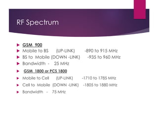
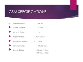
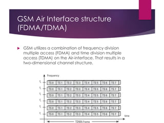
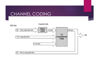
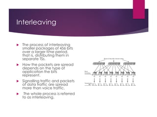
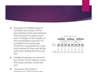
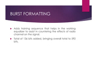
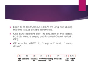
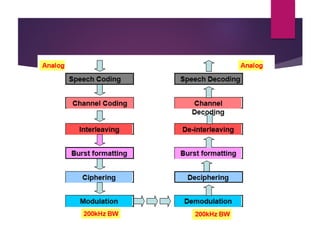
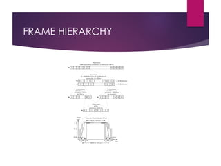


The document discusses the GSM air interface and its importance in mobile communication systems, detailing the RF spectrum, GSM specifications, and modulation methods. It explains the use of FDMA and TDMA for channel access, digital voice transmission, channel coding, interleaving, and various types of burst formats used in communication. Additionally, it covers the operational aspects of user access, synchronization, and features like discontinuous transmission and diversity to enhance connection quality.


