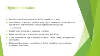
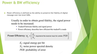
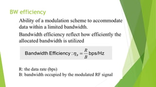
This document discusses digital modulation techniques used in modern mobile communication systems. It explains that digital modulation translates digital data into analog signals and provides advantages over analog transmission like greater noise immunity and easier multiplexing. Key factors that influence the choice of digital modulation scheme are low bit error rates, performance in fading environments, minimum bandwidth usage, and cost-effective implementation. Modulation techniques are evaluated based on their power efficiency and bandwidth efficiency. Power efficiency is defined as preserving signal fidelity at low signal-to-noise ratios, while bandwidth efficiency is utilizing the allocated bandwidth to maximize data throughput.


![Linear Modulation Techniques
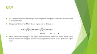
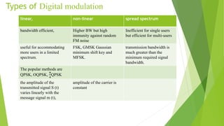
In linear modulation techniques, the amplitude of the transmitted signal, s(t), varies linearly with the
modulatng digital signal, m(t).
They are bandwidth efficient and hence are very attractive for use in wireless communication systems where
there is an increasing demand to accommodate more and more users within a limited spectrum.
In a linear modulation scheme, the transmitted signal s (t) can be expressed as [s(t) = Re [Am (t) exp
(j2πfct}
= A [mR (t) cos (2πfct)— mI (t) sin (2πfct)]
where A is the amplitude, fc is the carrier frequency, and m(t) = mR (t) + j mI (t) is a complex envelope
representation of the modulated signal
the amplitude of the carrier varies linearly with the modulating signal.
do not have a constant envelope. As shown subsequently, some nonlinear modulations may have either linear
or constant carrier envelopes, depending on whether or not the baseband waveform is pulse shaped.
While linear modulation schemes have very good spectral efficiency, they must be transmitted using linear
RF amplifiers which have poor power efficiency.
Using power efficient nonlinear amplifiers leads to the regeneration of filtered sidelobes which can cause
severe adjacent channel interference, and results in the loss of all the spectral efficiency gained by linear
modulation.](https://image.slidesharecdn.com/4thunit-221108085813-ec0418ce/85/Modulation_techniques4th-unit-pptx-20-320.jpg)