The document discusses multipath propagation, RAKE receivers, and Gaussian Minimum Shift Keying (GMSK). It provides the following key points:
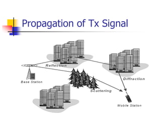
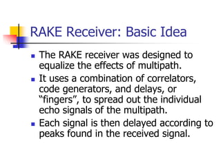
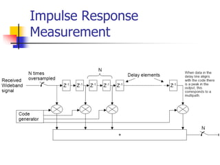
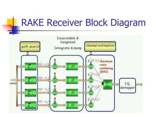
1) RAKE receivers were designed to equalize the effects of multipath propagation by using correlators, delays, and combining to separate multipath signals.
2) RAKE receivers combine symbols from different propagation paths using channel information and combining schemes like maximum ratio combining.
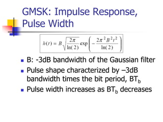
3) GMSK uses Gaussian filtering of minimum shift keying signals to achieve smooth phase transitions, reducing bandwidth requirements compared to minimum shift keying. However, it increases intersymbol interference.