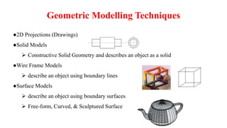
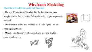
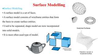
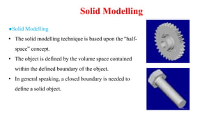
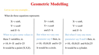
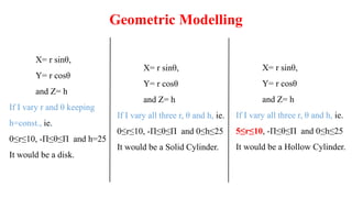
Geometric Modelling
• Modelling- Creating symbolic models of the physical world has long
been a goal of mathematicians, scientists, engineers, etc.
• Geometrical Modelling can be defined as computer friendly and
mathematical representation of geometry.
• Geometric Modelling is the computer-aided design and manipulation of
geometric objects.
• Geometric modelling is only a means not the goal in engineering.
●2D Projections (Drawings)
●Solid Models
 Constructive Solid Geometry and describes an object as a solid
●Wire Frame Models
 describe an object using boundary lines
●Surface Models
 describe an object using boundary surfaces
 Free-form, Curved, & Sculptured Surface
Geometric Modelling Techniques
●Wireframe Modelling (Auto-cad Drawings)
• The word “wireframe” is related to the fact that one may
imagine a wire that is bent to follow the object edges to generate
a model.
• Developed in 1960s and referred as “a stick figure” or “an
edge representation”
• Model consists entirely of points, lines, arcs and circles,
conics, and curves.
Wireframe Modelling
●Advantages
• Simple to construct
• Does not require as much as computer time and memory as does surface or solid modelling.
• As a natural extension of drafting, it does not require extensive training of users.
• From the basis for surface modelling as most surface algorithms require wireframe entities
(such as points, lines and curves)
●Disadvantages
• The input time is substantial and increases rapidly with the complexity of the object
• Both topological and geometric data need to be user-input; while solid modelling requires only
the input of geometric data.
• volume and mass properties, NC tool path generation, cross-sectioning, and interference cannot
be calculated.
Wireframe Modelling
●Surface Modelling
• A surface model is a set of faces.
• A surface model consists of wireframe entities that form
the basis to create surface entities.
• Used to be separated, shape model are now incorporated
into solid models.
• It is most often used type of model.
Surface Modelling
●Examples of Surface Modelling
• Surface models define only the geometry, no topology.
• Shading is possible.
Surface Modelling
●Advantages
• Less ambiguous
• Provide hidden line and surface algorithms to add realism to the displayed geometry
• Support volume and mass calculation, finite element modelling, NC path generation, cross
sectioning, and interference detection.
●Disadvantages
• Require more training and mathematical background of the users
• Require more CPU time and memory.
• Awkward to construct.
Surface Modelling
●Solid Modelling
• The solid modelling technique is based upon the "half-
space” concept.
• The object is defined by the volume space contained
within the defined boundary of the object.
• In general speaking, a closed boundary is needed to
define a solid object.
Solid Modelling
●Solid Modelling Support
• Using volume information
– weight or volume calculation, centroids, moments of
inertia calculation,
– stress analysis (finite elements analysis), heat conduction calculations,
– system dynamics analysis
• Using volume and boundary information
– generation of CNC codes, and robotic and assembly simulation.
Why Solid Modelling?
Geometric Modelling
X= r sinθ,
Y= r cosθ
and Z= h
When we give some values to
these 3 variables, ie.
r=10, θ= Π and h=25
It would be a point (X,Y,Z).
X= r sinθ,
Y= r cosθ
and Z= h
But when we vary one
parameter say θ then, ie.
r=10, -Π≤θ≤Π and h=25
It would be a circle.
X= r sinθ,
Y= r cosθ
and Z= h
But when I vary one more
parameter say θ and h then, ie.
r=10, -Π≤θ≤Π and 0≤h≤25
It would be a cylinder.
Let us see one example…
What do these equations represents
Geometric Modelling
X= r sinθ,
Y= r cosθ
and Z= h
If I vary r and θ keeping
h=const., ie.
0≤r≤10, -Π≤θ≤Π and h=25
It would be a disk.
X= r sinθ,
Y= r cosθ
and Z= h
If I vary all three r, θ and h, ie.
0≤r≤10, -Π≤θ≤Π and 0≤h≤25
It would be a Solid Cylinder.
X= r sinθ,
Y= r cosθ
and Z= h
If I vary all three r, θ and h, ie.
5≤r≤10, -Π≤θ≤Π and 0≤h≤25
It would be a Hollow Cylinder.
• Modelling Porous Medium
• Biomedical Applications
• Modelling Non-homogeneous Materials
– varying density
– changing composition
– multiple phases (solid, liquid)
New challenges to Geometric Modelling
Thank You…

Geometric Modelling in Computer Aided Design.pptx

  • 2.
    Geometric Modelling • Modelling-Creating symbolic models of the physical world has long been a goal of mathematicians, scientists, engineers, etc. • Geometrical Modelling can be defined as computer friendly and mathematical representation of geometry. • Geometric Modelling is the computer-aided design and manipulation of geometric objects. • Geometric modelling is only a means not the goal in engineering.
  • 3.
    ●2D Projections (Drawings) ●SolidModels  Constructive Solid Geometry and describes an object as a solid ●Wire Frame Models  describe an object using boundary lines ●Surface Models  describe an object using boundary surfaces  Free-form, Curved, & Sculptured Surface Geometric Modelling Techniques
  • 4.
    ●Wireframe Modelling (Auto-cadDrawings) • The word “wireframe” is related to the fact that one may imagine a wire that is bent to follow the object edges to generate a model. • Developed in 1960s and referred as “a stick figure” or “an edge representation” • Model consists entirely of points, lines, arcs and circles, conics, and curves. Wireframe Modelling
  • 5.
    ●Advantages • Simple toconstruct • Does not require as much as computer time and memory as does surface or solid modelling. • As a natural extension of drafting, it does not require extensive training of users. • From the basis for surface modelling as most surface algorithms require wireframe entities (such as points, lines and curves) ●Disadvantages • The input time is substantial and increases rapidly with the complexity of the object • Both topological and geometric data need to be user-input; while solid modelling requires only the input of geometric data. • volume and mass properties, NC tool path generation, cross-sectioning, and interference cannot be calculated. Wireframe Modelling
  • 6.
    ●Surface Modelling • Asurface model is a set of faces. • A surface model consists of wireframe entities that form the basis to create surface entities. • Used to be separated, shape model are now incorporated into solid models. • It is most often used type of model. Surface Modelling
  • 7.
    ●Examples of SurfaceModelling • Surface models define only the geometry, no topology. • Shading is possible. Surface Modelling
  • 8.
    ●Advantages • Less ambiguous •Provide hidden line and surface algorithms to add realism to the displayed geometry • Support volume and mass calculation, finite element modelling, NC path generation, cross sectioning, and interference detection. ●Disadvantages • Require more training and mathematical background of the users • Require more CPU time and memory. • Awkward to construct. Surface Modelling
  • 9.
    ●Solid Modelling • Thesolid modelling technique is based upon the "half- space” concept. • The object is defined by the volume space contained within the defined boundary of the object. • In general speaking, a closed boundary is needed to define a solid object. Solid Modelling
  • 10.
    ●Solid Modelling Support •Using volume information – weight or volume calculation, centroids, moments of inertia calculation, – stress analysis (finite elements analysis), heat conduction calculations, – system dynamics analysis • Using volume and boundary information – generation of CNC codes, and robotic and assembly simulation. Why Solid Modelling?
  • 11.
    Geometric Modelling X= rsinθ, Y= r cosθ and Z= h When we give some values to these 3 variables, ie. r=10, θ= Π and h=25 It would be a point (X,Y,Z). X= r sinθ, Y= r cosθ and Z= h But when we vary one parameter say θ then, ie. r=10, -Π≤θ≤Π and h=25 It would be a circle. X= r sinθ, Y= r cosθ and Z= h But when I vary one more parameter say θ and h then, ie. r=10, -Π≤θ≤Π and 0≤h≤25 It would be a cylinder. Let us see one example… What do these equations represents
  • 12.
    Geometric Modelling X= rsinθ, Y= r cosθ and Z= h If I vary r and θ keeping h=const., ie. 0≤r≤10, -Π≤θ≤Π and h=25 It would be a disk. X= r sinθ, Y= r cosθ and Z= h If I vary all three r, θ and h, ie. 0≤r≤10, -Π≤θ≤Π and 0≤h≤25 It would be a Solid Cylinder. X= r sinθ, Y= r cosθ and Z= h If I vary all three r, θ and h, ie. 5≤r≤10, -Π≤θ≤Π and 0≤h≤25 It would be a Hollow Cylinder.
  • 13.
    • Modelling PorousMedium • Biomedical Applications • Modelling Non-homogeneous Materials – varying density – changing composition – multiple phases (solid, liquid) New challenges to Geometric Modelling
  • 14.