This document provides information on the geometric design of highways. It discusses the key elements of highway design including the width of the carriageway and roadway, right of way, shoulders, side slopes, medians, and design speed. The objectives of geometric design are to optimize efficiency, safety, and cost while minimizing environmental impacts. Standard widths and specifications for elements like carriageways, medians, and shoulders are provided based on highway class and roadway conditions.
intersection are the space in which more than 2 roads crosses.types of road intersection,grade separated and at grade separated intersection.
intersection road
intersection tv series
the intersection grand rapids events
point of intersection calculator
intersection movie
intersection 1994
intersection season 4 on netflix
intersection grand rapids
at grade intersection, channelized intersection, diamond intersection, different types of road intersection, directional intersection, grade separated intersection, otary intersection, partial coverleaf intersection, road intersection definition, road intersection diagrams, roadway intersection types, trumpet intersection, un channelized intersection
The clear distance ahead of vehicle which is visible to the driver is known as sight distance
The minimum distance within which a driver can safely stop his vehicle without any collision with some vehicle, animal or any other object is known as stopping sight distance.
Highway Engineering for BE Civil Engineering Students
History of Roads in India, IRC, CRRI, Classification of Roads, Three 20 year Road Development Plans, Road patterns, Accident Studies,
Friction Considerations : The friction of skid resistance between vehicle tyre and pavement surface is one of the factors determining the operating speed and the minimum distance requires for stopping of vehicles.
Unevenness : The longitudinal profile of the road pavement has to be even' in order to provide a good riding comfort to fast moving vehicles
Light Reflecting Characteristics : Night visibility depends upon the colour and light reflecting characteristics of the pavement surface. The glare caused by the reflection of head lights is considerably high on wet pavement surface than on the dry pavement.
Drainage of Surface Water
Significance of Road, Rail, Air and Water transports - Coordination of all modes to achieve sustainability - Elements of permanent way – Rails, Sleepers, Ballast, rail fixtures and fastenings, - Track Stress, coning of wheels, creep in rails, defects in rails – Route alignment surveys, conventional and modern methods- - Soil suitability analysis - Geometric design of railways, gradient, super elevation, widening of gauge on curves- Points and Crossings
Highway planning and alignment: Different modes of transportation – historical Development of road construction- Highway Development in India –Classification of roads- Road pattern
– Highway planning in India- Highway alignment - Engineering Surveys for alignment – Highway Project- Important Transport/Highway related agencies in India. PMGSY project.
Introduction about IRC, NRRDA
A presentation on highway geometric design which includes:
definition,
Goals,
Road Alignment,
Its cross section,
Pavement Design, &
Theory about super Elevation
Sachpazis:Terzaghi Bearing Capacity Estimation in simple terms with Calculati...Dr.Costas Sachpazis
Terzaghi's soil bearing capacity theory, developed by Karl Terzaghi, is a fundamental principle in geotechnical engineering used to determine the bearing capacity of shallow foundations. This theory provides a method to calculate the ultimate bearing capacity of soil, which is the maximum load per unit area that the soil can support without undergoing shear failure. The Calculation HTML Code included.
Explore the innovative world of trenchless pipe repair with our comprehensive guide, "The Benefits and Techniques of Trenchless Pipe Repair." This document delves into the modern methods of repairing underground pipes without the need for extensive excavation, highlighting the numerous advantages and the latest techniques used in the industry.
Learn about the cost savings, reduced environmental impact, and minimal disruption associated with trenchless technology. Discover detailed explanations of popular techniques such as pipe bursting, cured-in-place pipe (CIPP) lining, and directional drilling. Understand how these methods can be applied to various types of infrastructure, from residential plumbing to large-scale municipal systems.
Ideal for homeowners, contractors, engineers, and anyone interested in modern plumbing solutions, this guide provides valuable insights into why trenchless pipe repair is becoming the preferred choice for pipe rehabilitation. Stay informed about the latest advancements and best practices in the field.
Hybrid optimization of pumped hydro system and solar- Engr. Abdul-Azeez.pdffxintegritypublishin
Advancements in technology unveil a myriad of electrical and electronic breakthroughs geared towards efficiently harnessing limited resources to meet human energy demands. The optimization of hybrid solar PV panels and pumped hydro energy supply systems plays a pivotal role in utilizing natural resources effectively. This initiative not only benefits humanity but also fosters environmental sustainability. The study investigated the design optimization of these hybrid systems, focusing on understanding solar radiation patterns, identifying geographical influences on solar radiation, formulating a mathematical model for system optimization, and determining the optimal configuration of PV panels and pumped hydro storage. Through a comparative analysis approach and eight weeks of data collection, the study addressed key research questions related to solar radiation patterns and optimal system design. The findings highlighted regions with heightened solar radiation levels, showcasing substantial potential for power generation and emphasizing the system's efficiency. Optimizing system design significantly boosted power generation, promoted renewable energy utilization, and enhanced energy storage capacity. The study underscored the benefits of optimizing hybrid solar PV panels and pumped hydro energy supply systems for sustainable energy usage. Optimizing the design of solar PV panels and pumped hydro energy supply systems as examined across diverse climatic conditions in a developing country, not only enhances power generation but also improves the integration of renewable energy sources and boosts energy storage capacities, particularly beneficial for less economically prosperous regions. Additionally, the study provides valuable insights for advancing energy research in economically viable areas. Recommendations included conducting site-specific assessments, utilizing advanced modeling tools, implementing regular maintenance protocols, and enhancing communication among system components.
Democratizing Fuzzing at Scale by Abhishek Aryaabh.arya
Presented at NUS: Fuzzing and Software Security Summer School 2024
This keynote talks about the democratization of fuzzing at scale, highlighting the collaboration between open source communities, academia, and industry to advance the field of fuzzing. It delves into the history of fuzzing, the development of scalable fuzzing platforms, and the empowerment of community-driven research. The talk will further discuss recent advancements leveraging AI/ML and offer insights into the future evolution of the fuzzing landscape.
COLLEGE BUS MANAGEMENT SYSTEM PROJECT REPORT.pdfKamal Acharya
The College Bus Management system is completely developed by Visual Basic .NET Version. The application is connect with most secured database language MS SQL Server. The application is develop by using best combination of front-end and back-end languages. The application is totally design like flat user interface. This flat user interface is more attractive user interface in 2017. The application is gives more important to the system functionality. The application is to manage the student’s details, driver’s details, bus details, bus route details, bus fees details and more. The application has only one unit for admin. The admin can manage the entire application. The admin can login into the application by using username and password of the admin. The application is develop for big and small colleges. It is more user friendly for non-computer person. Even they can easily learn how to manage the application within hours. The application is more secure by the admin. The system will give an effective output for the VB.Net and SQL Server given as input to the system. The compiled java program given as input to the system, after scanning the program will generate different reports. The application generates the report for users. The admin can view and download the report of the data. The application deliver the excel format reports. Because, excel formatted reports is very easy to understand the income and expense of the college bus. This application is mainly develop for windows operating system users. In 2017, 73% of people enterprises are using windows operating system. So the application will easily install for all the windows operating system users. The application-developed size is very low. The application consumes very low space in disk. Therefore, the user can allocate very minimum local disk space for this application.
Automobile Management System Project Report.pdfKamal Acharya
The proposed project is developed to manage the automobile in the automobile dealer company. The main module in this project is login, automobile management, customer management, sales, complaints and reports. The first module is the login. The automobile showroom owner should login to the project for usage. The username and password are verified and if it is correct, next form opens. If the username and password are not correct, it shows the error message.
When a customer search for a automobile, if the automobile is available, they will be taken to a page that shows the details of the automobile including automobile name, automobile ID, quantity, price etc. “Automobile Management System” is useful for maintaining automobiles, customers effectively and hence helps for establishing good relation between customer and automobile organization. It contains various customized modules for effectively maintaining automobiles and stock information accurately and safely.
When the automobile is sold to the customer, stock will be reduced automatically. When a new purchase is made, stock will be increased automatically. While selecting automobiles for sale, the proposed software will automatically check for total number of available stock of that particular item, if the total stock of that particular item is less than 5, software will notify the user to purchase the particular item.
Also when the user tries to sale items which are not in stock, the system will prompt the user that the stock is not enough. Customers of this system can search for a automobile; can purchase a automobile easily by selecting fast. On the other hand the stock of automobiles can be maintained perfectly by the automobile shop manager overcoming the drawbacks of existing system.
About
Indigenized remote control interface card suitable for MAFI system CCR equipment. Compatible for IDM8000 CCR. Backplane mounted serial and TCP/Ethernet communication module for CCR remote access. IDM 8000 CCR remote control on serial and TCP protocol.
• Remote control: Parallel or serial interface.
• Compatible with MAFI CCR system.
• Compatible with IDM8000 CCR.
• Compatible with Backplane mount serial communication.
• Compatible with commercial and Defence aviation CCR system.
• Remote control system for accessing CCR and allied system over serial or TCP.
• Indigenized local Support/presence in India.
• Easy in configuration using DIP switches.
Technical Specifications
Indigenized remote control interface card suitable for MAFI system CCR equipment. Compatible for IDM8000 CCR. Backplane mounted serial and TCP/Ethernet communication module for CCR remote access. IDM 8000 CCR remote control on serial and TCP protocol.
Key Features
Indigenized remote control interface card suitable for MAFI system CCR equipment. Compatible for IDM8000 CCR. Backplane mounted serial and TCP/Ethernet communication module for CCR remote access. IDM 8000 CCR remote control on serial and TCP protocol.
• Remote control: Parallel or serial interface
• Compatible with MAFI CCR system
• Copatiable with IDM8000 CCR
• Compatible with Backplane mount serial communication.
• Compatible with commercial and Defence aviation CCR system.
• Remote control system for accessing CCR and allied system over serial or TCP.
• Indigenized local Support/presence in India.
Application
• Remote control: Parallel or serial interface.
• Compatible with MAFI CCR system.
• Compatible with IDM8000 CCR.
• Compatible with Backplane mount serial communication.
• Compatible with commercial and Defence aviation CCR system.
• Remote control system for accessing CCR and allied system over serial or TCP.
• Indigenized local Support/presence in India.
• Easy in configuration using DIP switches.
Overview of the fundamental roles in Hydropower generation and the components involved in wider Electrical Engineering.
This paper presents the design and construction of hydroelectric dams from the hydrologist’s survey of the valley before construction, all aspects and involved disciplines, fluid dynamics, structural engineering, generation and mains frequency regulation to the very transmission of power through the network in the United Kingdom.
Author: Robbie Edward Sayers
Collaborators and co editors: Charlie Sims and Connor Healey.
(C) 2024 Robbie E. Sayers
NO1 Uk best vashikaran specialist in delhi vashikaran baba near me online vas...Amil Baba Dawood bangali
Contact with Dawood Bhai Just call on +92322-6382012 and we'll help you. We'll solve all your problems within 12 to 24 hours and with 101% guarantee and with astrology systematic. If you want to take any personal or professional advice then also you can call us on +92322-6382012 , ONLINE LOVE PROBLEM & Other all types of Daily Life Problem's.Then CALL or WHATSAPP us on +92322-6382012 and Get all these problems solutions here by Amil Baba DAWOOD BANGALI
#vashikaranspecialist #astrologer #palmistry #amliyaat #taweez #manpasandshadi #horoscope #spiritual #lovelife #lovespell #marriagespell#aamilbabainpakistan #amilbabainkarachi #powerfullblackmagicspell #kalajadumantarspecialist #realamilbaba #AmilbabainPakistan #astrologerincanada #astrologerindubai #lovespellsmaster #kalajaduspecialist #lovespellsthatwork #aamilbabainlahore#blackmagicformarriage #aamilbaba #kalajadu #kalailam #taweez #wazifaexpert #jadumantar #vashikaranspecialist #astrologer #palmistry #amliyaat #taweez #manpasandshadi #horoscope #spiritual #lovelife #lovespell #marriagespell#aamilbabainpakistan #amilbabainkarachi #powerfullblackmagicspell #kalajadumantarspecialist #realamilbaba #AmilbabainPakistan #astrologerincanada #astrologerindubai #lovespellsmaster #kalajaduspecialist #lovespellsthatwork #aamilbabainlahore #blackmagicforlove #blackmagicformarriage #aamilbaba #kalajadu #kalailam #taweez #wazifaexpert #jadumantar #vashikaranspecialist #astrologer #palmistry #amliyaat #taweez #manpasandshadi #horoscope #spiritual #lovelife #lovespell #marriagespell#aamilbabainpakistan #amilbabainkarachi #powerfullblackmagicspell #kalajadumantarspecialist #realamilbaba #AmilbabainPakistan #astrologerincanada #astrologerindubai #lovespellsmaster #kalajaduspecialist #lovespellsthatwork #aamilbabainlahore #Amilbabainuk #amilbabainspain #amilbabaindubai #Amilbabainnorway #amilbabainkrachi #amilbabainlahore #amilbabaingujranwalan #amilbabainislamabad
CFD Simulation of By-pass Flow in a HRSG module by R&R Consult.pptxR&R Consult
CFD analysis is incredibly effective at solving mysteries and improving the performance of complex systems!
Here's a great example: At a large natural gas-fired power plant, where they use waste heat to generate steam and energy, they were puzzled that their boiler wasn't producing as much steam as expected.
R&R and Tetra Engineering Group Inc. were asked to solve the issue with reduced steam production.
An inspection had shown that a significant amount of hot flue gas was bypassing the boiler tubes, where the heat was supposed to be transferred.
R&R Consult conducted a CFD analysis, which revealed that 6.3% of the flue gas was bypassing the boiler tubes without transferring heat. The analysis also showed that the flue gas was instead being directed along the sides of the boiler and between the modules that were supposed to capture the heat. This was the cause of the reduced performance.
Based on our results, Tetra Engineering installed covering plates to reduce the bypass flow. This improved the boiler's performance and increased electricity production.
It is always satisfying when we can help solve complex challenges like this. Do your systems also need a check-up or optimization? Give us a call!
Work done in cooperation with James Malloy and David Moelling from Tetra Engineering.
More examples of our work https://www.r-r-consult.dk/en/cases-en/
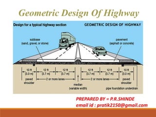
1. Geometric Design Of Highway
PREPARED BY = P.R.SHINDE
email id : pratik2150@gmail.com
2. Introduction:
• The geometric design of roads is the branch of highway
engineering concerned with the positioning of the
physical elements of the roadway according to standards
and constraints. The basic objectives in geometric designs
are to optimize efficiency and safety while minimizing cost
and environmental damage.
5. 5
ELEMENTS OF ROADS
1. Width of Pavement or Carriageway:
It is total width of road on which vehicles are allowed to move.
The width of pavement depends on width of traffic lane
and number of lanes.
Width of lane is decided based on maximum width of heavy
commercial vehicle (HCV) which is legally permitted to use the
roadway.
9. 9
•The width of carriageway for various classes of roads
standardised by Indian Roads Congress (IRC) are given
below:
Class Of Road Width Of
Carriageway (m)
Single lane road 3.75
Two lanes, without raised
kerbs
7
Two lanes, with raised kerbs 7.5
Intermediate Carriageway 5.5
Multi-lane pavements 3.5 per lane
10. 10
2. Width of Formation or Roadway:
Width of formation or roadway is the sum of widths of pavement or
carriageway including separators, if any and the shoulders.
11. 11
Sr.
No
Road Classification Roadway Width (m)
Plain and
rolling terrain
Mountainous
and steep terrain
1
National & State Highways
a) Single Lane
b) Two lane
12 6.25
12 8.80
2
Major District Roads
a) Single Lane
b) Two lane
9 4.75
9 -
3
Other District Roads
a) Single Lane
b) Two lane
7.5 4.75
9 -
4 Village Roads ,Single Lane 7.5 4
Width of roadway are standardized by the Indian Roads Congress.
12. 3. Right of way:-
• Right of way is the area of land acquired for the road, along its
alignment. It is the distance between the boundary stones on
either side of the road. RoW is the area of the road acquired for
carriages way + other necessities + future extension, along its
alignment.
4. Road shoulders:-
• Shoulders are provided
along the road edge to
serve as emergency lane
for vehicles. As per IRC, the
minimum width of
shoulders should be 2.5m.
Road shoulders
13. 5. Side slope:-
The slope of earthwork in filling or in cutting is called Side
slope. It imparts stability to the earthwork.
Typeof soil Slope
Ordinary soil 1:1 to 1:1/2
Broken Rock 1:1/2 to 1:1/4
Soft Rock 1:1/4 to 1:1/8
Hard Rock Approx. Perpendicular
14. 6.Berm:-
• The distance between the roadtoe and the inner edge of
borrow pit is called berm.
• It prevents the erosion of embankment soil.
7. Boundary stone :-
• To indicate the boundary of land acquired for road, stones
are driven in to the ground at about 30m distance on
either side from the center line of the road. These stones
are known as boundary stone.
15. 8. Side drain:-
• For the drainage of
rainwater, drains are
provided on either side
of the road. Normally,
side drains are required
for the road in cutting.
For road in embankment,
side drain is not
necessary.
9. Building line:-
• The distance from the center line of road on either side,
within which construction of buildings is not permitted is
called Building line.
Side drain
16. 10.Control line:-
• At the locations like bank, hospital, factory, theatre, etc. on
the road, where more people gather disturbance to the
traffic will be more.
11.Spoil bank:-
• The banks constructed from surplus excavated earth on the
side of road cutting parallel to its alignment, are known as
Spoil banks.
• The soil from spoil bank can be used for the repair of
shoulders.
17. 12.Borrow pits:-
•The pits dug along the road alignment for using excavated earth
in the construction of embankment, are known as borrow pits.
•The small portion of earth left undug in a borrow pit to measure
depth of excavation is known as deadman.
18. 18
13. KERBS :
• Kerbs indicates the boundary between the pavement and
median or foot path or shoulder.
• Kerbs may be mainly divided into three groups based on their
functions- 1. Low kerb 2. Semi-barrier type kerb 3. Barrier type kerb
19. 1. Low or mountable kerbs : This type of kerbs are provided such
that they encourage the traffic to remain in the through traffic
lanes and also allow the driver to enter the shoulder area with
little difficulty. The height of this kerb is about 10 cm above the
pavement edge with a slope which allows the vehicle to climb
easily. This is usually provided at medians and channelization
schemes and also helps in longitudinal drainage.
2. Semi-barrier type kerbs : When the pedestrian traffic is high,
these kerbs are provided. Their height is 15 cm above the
pavement edge. This type of kerb prevents encroachment of
parking vehicles, but at acute emergency it is possible to drive
over this kerb with some difficulty.
3. Barrier type kerbs : They are designed to discourage vehicles
from leaving the pavement. They are provided when there is
considerable amount of pedestrian traffic. They are placed at a
height of 20 cm above the pavement edge with a steep batter.
21. 14. Road Formation
The Road Formation is the surface of finished earthworks on
which a road pavement is constructed. It includes the
earthworks, the general shaping of the road and
basic drainage, but excluding storm water infrastructure.
22. 22
15. Cross slope or camber:
Cross slope or camber is the slope provided to the road surface
in the transverse direction to drain off the rain water from the
road surface. Drainage and disposal of water from pavement is
considered important because of the following reason:
• To maintain stability, surface condition and increase life of
pavement.
• Topreventstrippingofbitumenfromaggregates.
• Topreventslippingofvehiclesrunningathigh speed.
• Therateofcamberorcrossslopeisusually designatedby1innor
mayalsobeexpressedasa percentage.
• The required camber of a pavement depends on type of
pavementsurfaceandamountofrainfall.
23. The values of camber recommended by IRC for
different types of road surfaces are given below:
Sr.No Type Of Road Surface Range of camber in areas of
Heavy rainfall Low rainfall
1 Cement concrete and
thick bituminous
surface
1 in 50 or 2 % 1 in 60 or 1.7 %
2 Thin bituminous
surface
1 in 40 or 2.5% 1 in 50 or 2 %
3 Water bound macadam
and gravel pavement
1 in 33 or 3% 1 in 40 or 2.5 %
4 Earth road 1 in 25 or 4% 1 in 33 or 3 %
14
26. 16. Road Margins
Road margins are the various cross sectional elements of the
road except the carriageway or pavement width.
Various road margins are shoulders, foot-paths, cycle-tracks,
frontage paths, driveways, lay byes, side slopes and guide rails.
• Shoulders: Shoulders are the parts of the formation width
except carriage ways. In other words, shoulder is the part of
the pavement which is non-surfaced.
• They are used by the vehicular traffic as the emergency lanes
or sometimes as the service lanes for the repairing of the non-
expected problems. IRC recommends a minimum value 2.5 m
for the shoulders for two lane rural roads. A width of 4.6 m is
recommended so that a truck can be accommodated without
interfering with the adjacent lane.
27. •Footpaths: Foot paths or pedestrian paths are the smoothly
paved paths used by the pedestrians to walk parallel to the
pavements. Footpaths are smoothly surfaced in order to attract
the pedestrians to walk over them. Footpaths are necessary
where the pedestrian traffic is considerable.
•Cycle-tracks: Cycle tracks are provided to carry the cyclists. They
are generally provided in the urban roads where the design
speed is very high and it becomes necessary to separate the high
speed traffic from the low speed traffic. Minimum of 2 m width is
recommended for single lane and 1 m is added for constructing
the extra lanes of the cycle tracks.
•Frontage Paths: They are provided in front of the commercial
buildings where it becomes a necessity. In urban areas they are
provided with the dividers to separate from the vehicular lanes.
28. •Drive-ways: Drive ways are provided to reach the buildings like
fuel pumps or service centres. Drive ways should have a less
width as much as possible because they are hindrance to the
pedestrian traffic travelling along the foot-paths.
•Parking Lanes: They are provided for parking the vehicular
traffic generally needed in the market centers or the urban
areas. Parallel parking is recommended in order to avoid the
hindrance to the traffic and a minimum of 3 m parking lane is
recommended.
•Side Slopes: A proper, flatter/gentle side slopes are necessary in
case of filling or cutting for the stability of the pavements. If
possible they must be provided with the landscaping so making
them a pleasant and aesthetic appearance and making more
stable.
29. • Guide Rails: Guide rails are provided on the roads on
filling generally on the hills, on the outer edges, for the
psychological as well as physical protection to the
driver.
• Lay Byes: Lay Byes are the paved areas provided at some
places on the sides of the lanes for providing a stoppage
for the vehicles.
30. 17. Median or Traffic Separator:
30
Median is provided between two sets of traffic lanes intended to
divide the traffic moving in opposite directions.
The main function of the median is to prevent head-on
collision between vehicles moving in opposite directions on
adjacent lanes.
The traffic separators used may be in form of pavement
markings, physical dividers or area separators.
32. 32
•The width of medians for roads standardised by
Indian Roads Congress (IRC) are given below:
Sr.No Type Of Road Width Of Medians (m)
Desirable Minimum
1 Expressway 15 10
2 Other Highways 5 3
3 At intersection of
urban roads
5 1.2
4 On Long Bridges 1.5 1.2
34. 34
Design speed
•The design speed is the main factor on which geometric design
elements depends. Design speed is a selected speed used to
determine the various geometric features of the roadway. The sight
distance, radius of horizontal curve, superelevation, extra widening of
pavement, length of horizontal transition curve and the length of
summit and valley curve are all depends on design speed.
Factors affecting design speed
The road's functional classification (class of road)
Terrain
The speed standards of a particular class of road thus depends on the
classification of the terrain through which it passes. The terrain have
been classified as plain, rolling, mountainous and steep, depending
on the cross slope of a country as given below.
35. Classification of Terrain
35
Terrain Classification Cross Slope Of Country
in %
Plain 0-10
Rolling 10-25
Mountainous 25-60
Steep Greater than 60
36. 36
Design Speed On highways
The design speed (ruling & minimum) standardized by the
IRC for different classes of roads on different terrains in rural
areas are given below.
37. 37
Gradients:
Gradient is the rate of rise or fall along the length of road with
respect to the horizontal. It is expressed as a ratio of 1 in n or also
as percentage such as n%.
Types Of Gradients:
Ruling gradient
Limiting gradient
Exceptional gradient
Minimum gradient
‘
38. 38
Ruling gradient:
• Ruling gradient is the maximum gradient within which the
designer attempts to design the vertical profile of a road.
Ruling gradient is also known as ‘Design gradient’.
• For selection of ruling gradient factors such as type of terrain,
length of the grade, speed, pulling power of vehicle etc. are
considered. In flatter terrain, it may be possible to provide at
gradients, but in hilly terrain it is not economical and
sometimes not possible also
Limiting gradient:
• This gradient is adopted when the ruling gradient results in
enormous increase in cost of construction. On rolling terrain
and hilly terrain it may be frequently necessary to adopt
limiting gradient.
‘
39. 39
Exceptional gradient:
• Exceptional gradient are very steeper gradients given at
unavoidable situations.
• They should be limited for short stretches not exceeding
about 100 m at a stretch.
Minimum gradient:
• This is important only at locations where surface drainage is
important. Camber will take care of the lateral drainage.
• But the longitudinal drainage along the side drains require
some slope for smooth flow of water. Therefore minimum
gradient is provided for drainage purpose and it depends
on the rain fall, type of soil and other site conditions.
• A minimum of 1 in 500 may be sufficient for concrete drain
and 1 in 200 for open soil drains are found to give
satisfactory performance..
40. 40
‘
Type of terrain Ruling
gradient
Limiting
gradient
Exceptional
gradient
Plain and rolling 3.3 %
1 in 30
5%
1 in20
6.7 %
1 in 15
Mountainous and steep having
elevation more than 3000 m above
MSL
5%
1 in20
6 %
1 in 16.7
7 %
1 in 14.3
Mountainous and steep having
elevation more than 3000 m above
MSL
6 %
1 in 16.7
7 %
1 in 14.3
8 %
1 in 12.5
41. SIGHT DISTANCE:
• The actual distance that is observed along the road surface
which is visible for a driver from a specified height above
the carriage way is called as the sight distance at a point.
This distance will let the driver see all the stationary and
the moving objects in front of the vehicle.
• Mainly in the geometric design of road construction,
mainly three sight distances are taken into consideration.
They are:
SSD – Stopping Sight Distance or Absolute Minimum Sight
Distance
ISD – Intermediate Sight Distance: This is twice the value of
SSD
OSD – Overtaking Sight Distance.
42. Stopping Sight Distance:
• This is defined as the sight distance that is available for
the moving the vehicle in the highway that will enable
the driver to stop the vehicle safely without collision
with any other obstacle.
43. The sight distance available on a road to a driver at any
instance depends on :
1. Features of the road ahead.
2. Height of the driver’s eye above the road surface.
3. Height of the object above the road surface.
The distance within which a motor vehicle can be
stopped depends upon the factors listed below:
1. Total reaction time of the driver.
2. Speed of vehicle
3. Efficiency of breaks
4. Frictional resistance between the road and the tyres.
5. Gradient of the road.
44. 44
Overtaking Sight Distance:
• The minimum distance available for the driver to safely overtake
the slow vehicle in front of him by considering the traffic in the
opposite direction is called as the overtaking sight distance or safe
passing sight distance available.
• This distance will make us see whether the road is clear to
undergo an overtaking movement.
Factors on which overtaking sight distance affects
Spacing Between the vehicles.
Speed of the vehicles.
The gradient of the road.
The acceleration rate of the overtaking vehicle.
The velocities of the vehicle which is overtaking, overtaken and
that coming in the opposite direction.
The driver skill.
The reaction of the driver.
45. Intermediate sight distance:
• This is defined as twice the stopping sight distance. When
overtaking sight distance can not be provided,
intermediate sight distance is provided togive limited
overtaking opportunities to fast vehicles.
46. Curve
• A curve is nothing but an arc which connects two straight
lines which are separated by some angle called deflection
angle.
• This situation occurs where the alignment of a road way
changes its direction because of unavoidable objects or
conditions.
• The object may be a hill or a lake or a temple etc. so, for
the ease of movement of vehicle at this point a curve is
provided.
Necessity of curves
• Try to avoid a large obstacle.
• To reduce the steepness, or grade, of the roadway on a hill.
47. Types of Curves in Alignment of Highways
In general, there are two types of curves and they are
• Horizontal curves
• Vertical curves
Horizontal Curves:
• The curve provided in the horizontal plane of earth is called
as horizontal curve. It connects two straight lines which are
in same level but having different directions. Horizontal
curves are of different types as follows:
1. Simple circular curve
2. Compound curve
3. Reverse curve
4. Transition curve
5. Spiral
6. Lemniscate
48. 1. Simple Circular Curve:
• Simple circular curve is normal horizontal curve which connect
two straight lines with constant radius.
2. Compound Curve:
• Compound curve is a
combination of two or more
simple circular curves with
different radii. In this case both
or all the curves lie on the same
side of the common tangent.
49. 3. Reverse Curve
• Reverse curve is formed when two simple circular curves
bending in opposite directions are meet at a point. This points
is called as point of reverse curvature.
• The centre of both the curves lie on the opposite sides of the
common tangent.
• The radii of both the curves may be same or different.
50. 4. Transition Curve
• A curve of variable radius is termed as transition curve. It is
generally provided on the sides of circular curve or between the
tangent of circular curve. Its radius varies from infinity to a
certain fixed value.
• Transition curve helps gradual introduction of centrifugal force
by gradual super elevation which provides comfort for the
passengers in the vehicle without sudden jerking.
51. 5. Spiral Curve
• Spiral is a type of transition curve which is recommended by
IRC as ideal transition curve because of its smooth
introduction of centrifugal acceleration. It is also known as
clothoid.
52. 6. Lemniscate curve
• Lemniscate is a type of transition curve which is used when the
deflection angle is very large. In lemniscate the radius of curve is
more if the length of chord is less.
53. Vertical Curves
The curves provided in vertical plane of earth is called as
vertical curve. This type of curves are provided when the
ground is non-uniform or contains different levels at different
points.
vertical curves are divided into two types
1. Valley curve
2. Summit curve
54. 1. Valley Curve:
• Valley curve connects falling gradient with rising gradient so,
in this case convexity of curve is generally downwards. It is
also called as sag curve.
55. 2. Summit Curve
• Summit curve connects rising gradient with falling
gradient hence, the curve has its convexity upwards. It is
also called as crest curve.
56. WIDENING OF ROADS
• On horizontal curves , especially when they are not of very large
radius, it is a common practice to widen the pavement slightly
more than the normal width, the object of providing Extra
Widening of pavements on horizontal curves are due to the
following reasons....
(a) An automobile such as car, bus or truck has a rigid wheel base
and only the front wheels can be turned. When the vehicle takes a
turn to negotiate a horizontal curve, the rear wheels do not follow
the same path as that of the front wheels. This phenomenon is
called ‘off tracking’. The off tracking depends on
the length of the wheel base of the vehicle
the turning angle or the radius of the horizontal curves.
57. (b)At more than design speed if super elevation and lateral
friction jointly cannot counteract the centrifugal force, full
outward slipping of rear wheels may occur and thus more width
of road is covered. This condition occurs at very high speeds.
(c)At start of the curves drivers have a tendency to follow outer
edge of the pavement to have better visibility and large radius
curved path. This also necessitates extra width of the road.
(d)While overtaking operations on horizontal curves driver will
need more spacing from the other vehicles to feel safer.
58. Analysis of extra widening on horizontal curves
The extra widening of pavement on horizontal curves is
divided in to two parts
(i) Mechanical widening and
(ii) Psychological widening.
I) Mechanical widening :-
• The widening required to account for the off tracking due to
the rigidity of wheel base is called Mechanical widening .
Formula of calculating mechanical widening is
W = Nl2__
2R
Here,
n =number of traffic lanes
l = length of wheel base of longest vehicle in m
R= radius of horizontal curves in m
59. II) Psychological widening :-
At horizontal curves drivers have a tendency to maintain a
greater clearance between the vehicles than on straight stretches
of road. Therefore an extra width of pavement is provided for
psychological reasons for greater manoeuvrability of steering at
higher speeds and to allow for the extra space requirements for
the overhangs of vehicles. Psychological widening is therefore
important in pavements with more than one lane. An empirical
formula has been recommended by IRC for deciding the
additional psychological widening Wps which is dependent on the
design speed, V of the vehicle and the radius. R of the curve. The
psychological widening is given by the formula:
Wps
60. Hence the total widening We required on a horizontal curve is
given by:
We= Wm + Wps
+
Here,
n =number of traffic lanes
l = length of wheel base of longest vehicle in m
R= radius of horizontal curves in m
V= design speed Kmph
W =
__
2R
Nl2
61. The extra width recommended by the Indian Road Congress
for single and two lane pavements are given in table:
62. Super elevation (e)
62
• In order to counteract the effect of centrifugal force and to
reduce the tendency of the vehicle to overturn or skid, the outer
edge of the pavement is raised with respect to the inner edge,
thus providing transverse slope through out the horizontal curve.
This transverse inclination of pavement surface is known as super
elevation or cant or banking. The Super elevation ‘e’ is expressed
as the ratio of the height of outer edge with respect to the
horizontal width.
63. The general equation for the design of super elevation is given by,
e + f = v²∕gR
Where,
e = rate of Super elevation in %
V = velocity of vehicle in m/s
f = lateral friction factor = 0.15
g = acceleration due to gravity = 9.81 m/s2
R = radius of circular curve in meters.
If velocity is in KMPH then e + f = V2/ 127R
63
64. 64
Maximum Super elevation
• as per above equation the value of super elevation needed
increases with increase in speed and with decrease in radius of
the curve, for a constant value of coefficient of lateral friction f.
In a highway, with mixed traffic, the value of super elevation so
obtained from equations is to be limited to avoid the danger of
overturning. This maximum allowable limit of super elevation is
called maximum super elevation.
• Indian Roads Congress (IRC) had fixed the maximum limit of
Super elevation in plan and rolling terrains and in snow bound
areas as 7.0 %.
• On hill roads not bound by snow a maximum Superelevation
upto10% is recommended.
• On urban road stretches with frequent intersections, it
may be necessary to limit the maximum Superelevation
to 4.0 %.
65. 65
Minimum Superelevation
• If the value of super elevation obtained from the equations is
equal or less than the usual camber value provided to the road
surface then it should be equal to the camber slope. This lower
limit of super elevation equal to the amount of camber is termed
as minimum super elevation. It is (2-4) % for drainage purposes,
especially for large radius horizontal curve
66. Method Of Providing Super elevation
Introduction of super elevation on a horizontal curve of a road is
an important feature in road construction. Super elevation is
provided in the following two methods.
1.Elimination of the crown of the cambered section.
2.Rotation of pavement to attain full super elevation.
1. Elimination of The Crown of The Cambered Section
• In this method, the outer half of the camber is gradually
decreased.
• This may be done by two methods.
67. • In the first method, the outer half of the camber is rotated
about the crown at the desired rate such that the surface
falls on the same plane as the inner half.
68. • In the second method, the crown is progressively shifted
outwards. This method is not usually adopted.
69. 2. Rotation of Pavement To Attain Full Superelevation
• In this stage, super elevation is gradually provided over the
full width of the carriageway so that the required super
elevation is available at the beginning of the circular
curve.
• The different method employed for attaining the super
elevation is as follows:
70. A. Revolving Pavement About The Centre Line
• In this method the surface of the road is rotated
about the centre line of the carriageway, gradually
lowering the inner edge and rising the upper edge.
The level of the centre line is kept constant. This
method is widely used.
71. B. Revolving Pavement About The Inner Edge
• In this method, the surface of the road is rotated about
the inner edge, raising the centre and outer edge.
C. Revolving Pavement About The Outer Edge
In this method, the surface of the road is rotated about the
outer edge depressing the centre and inner edge.