Downloaded 2,468 times
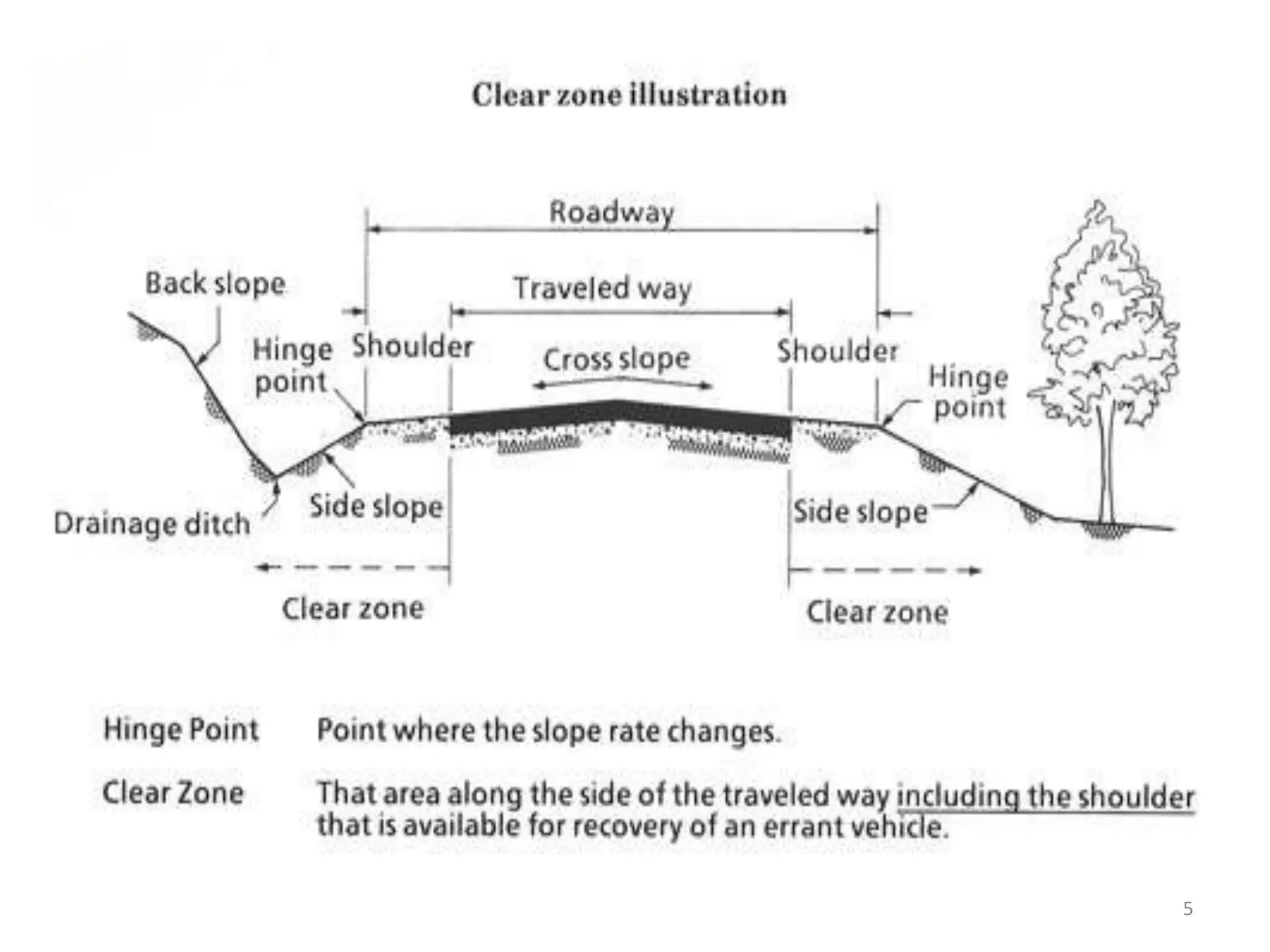
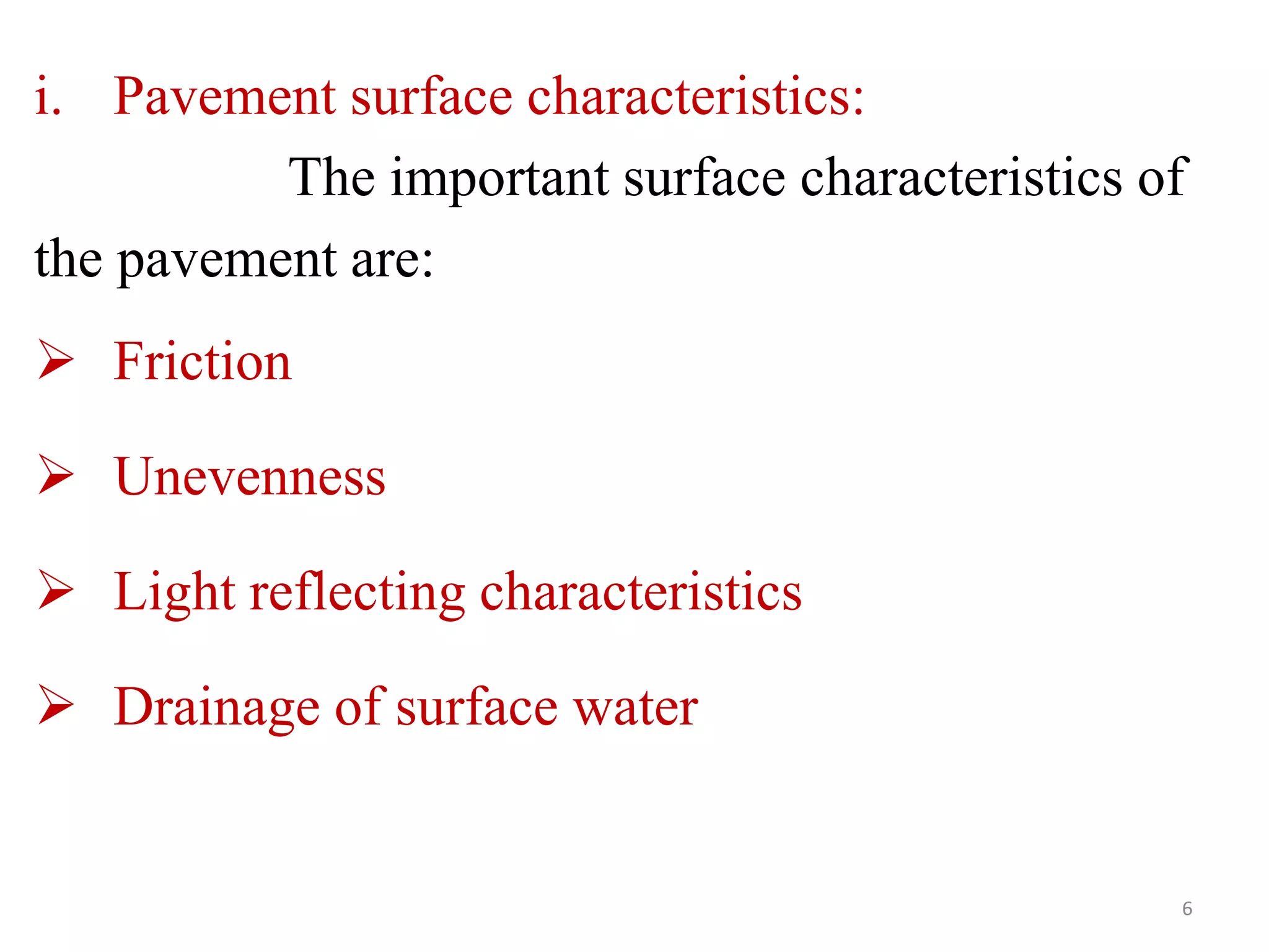
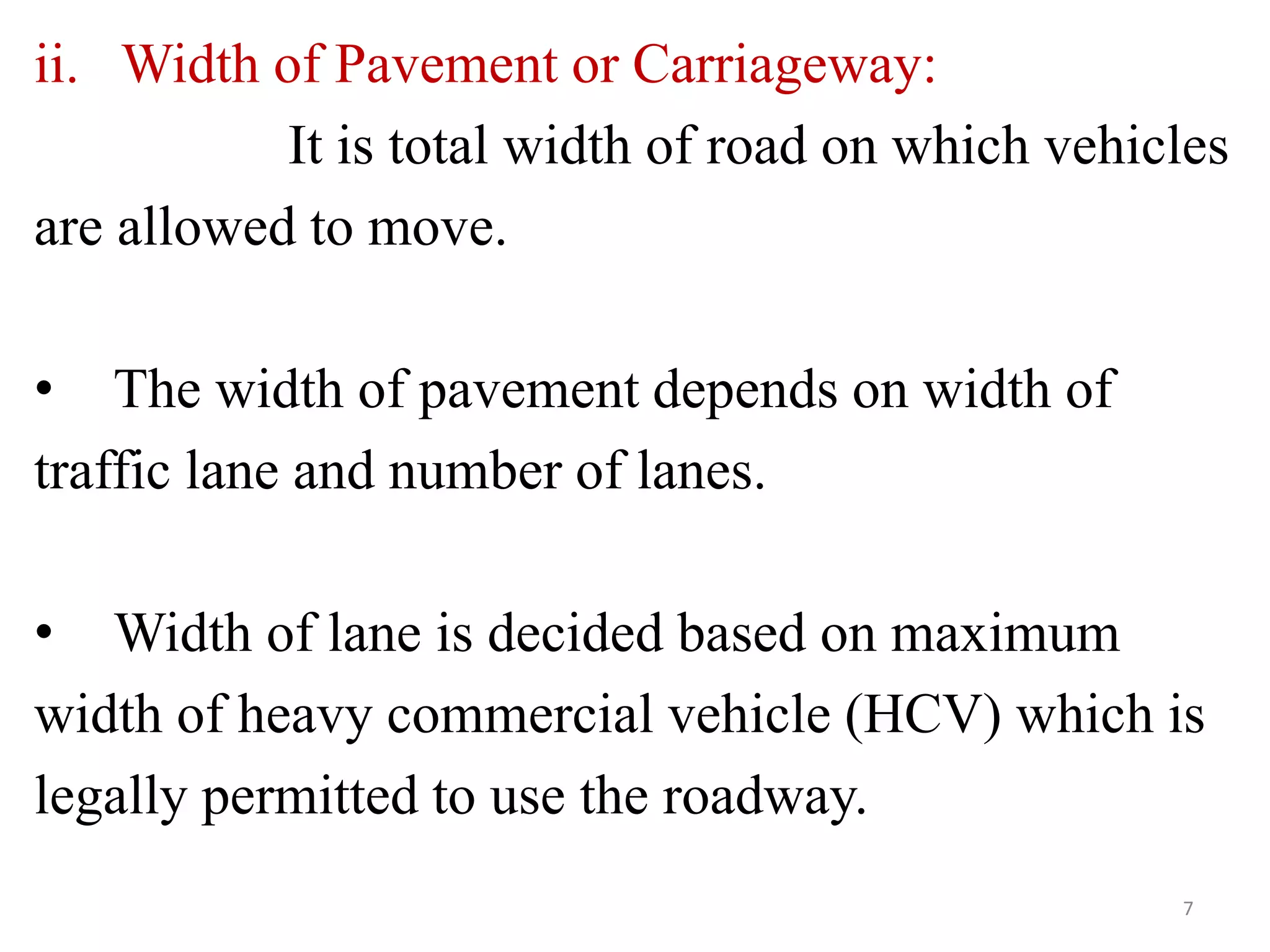
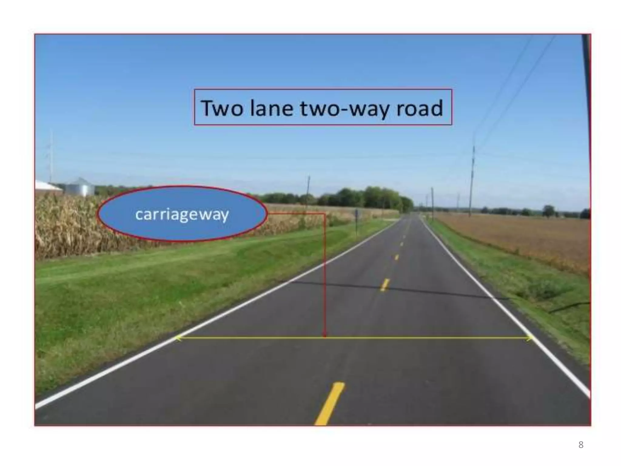
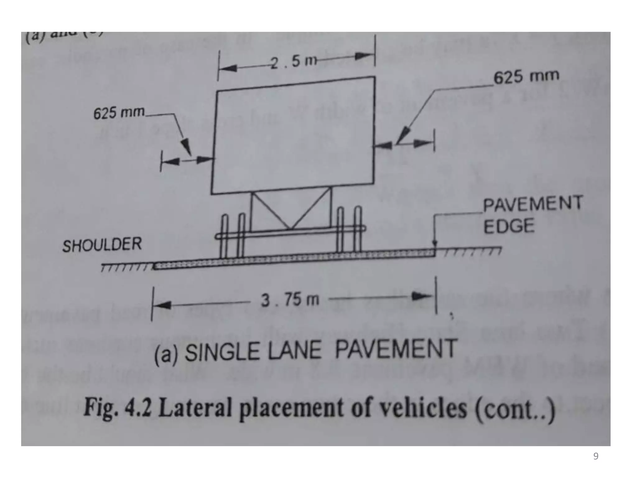
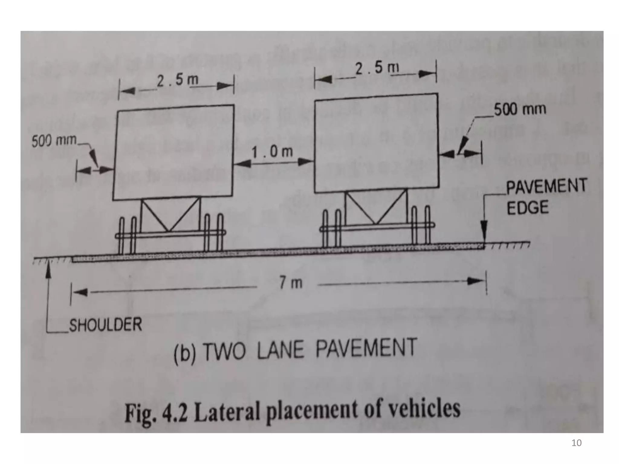
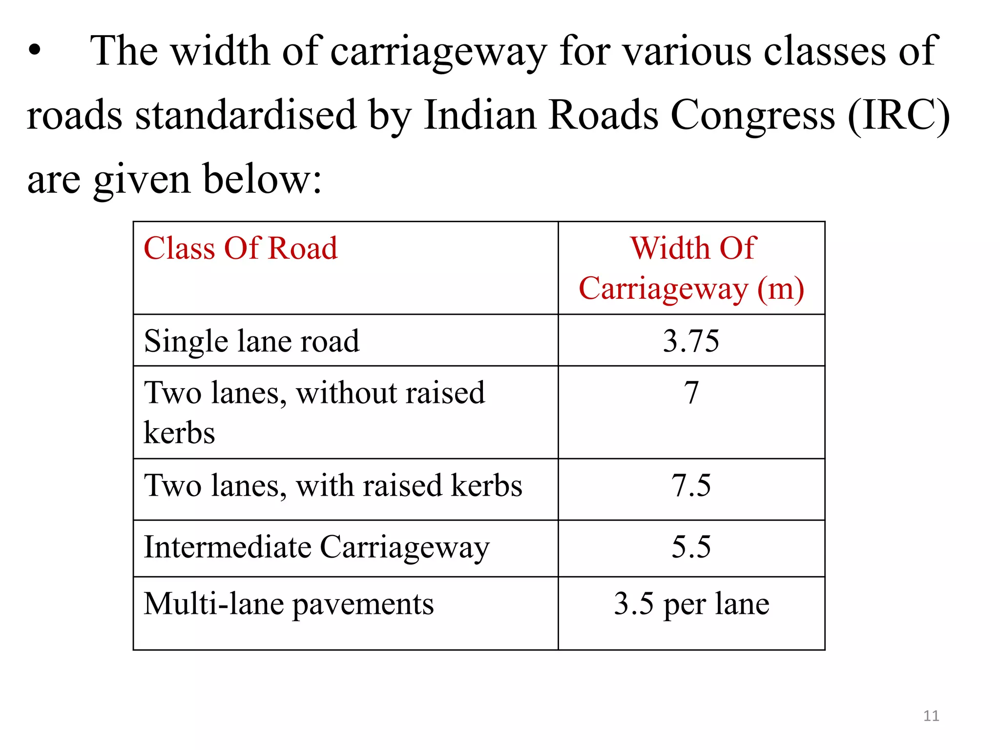
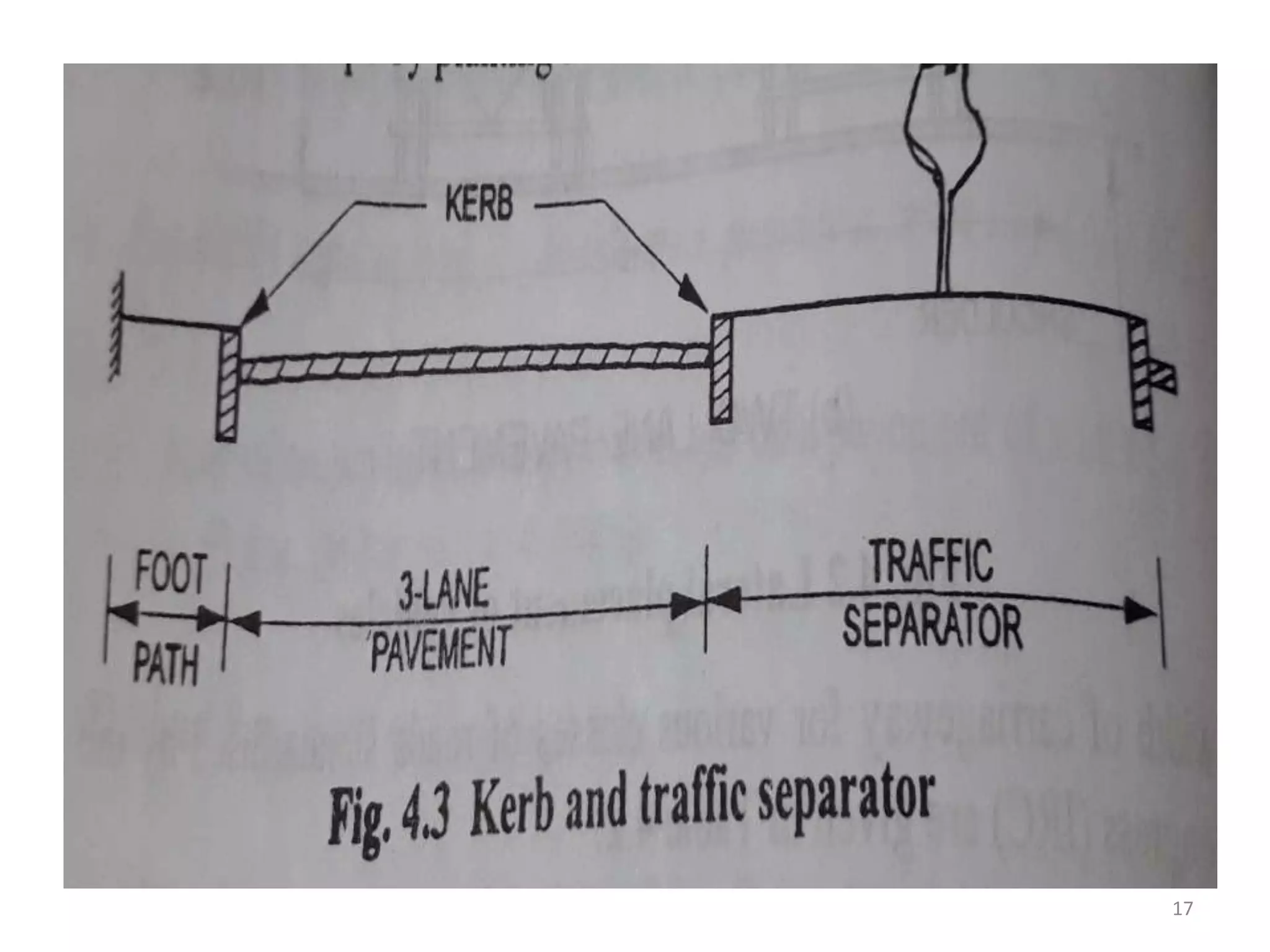
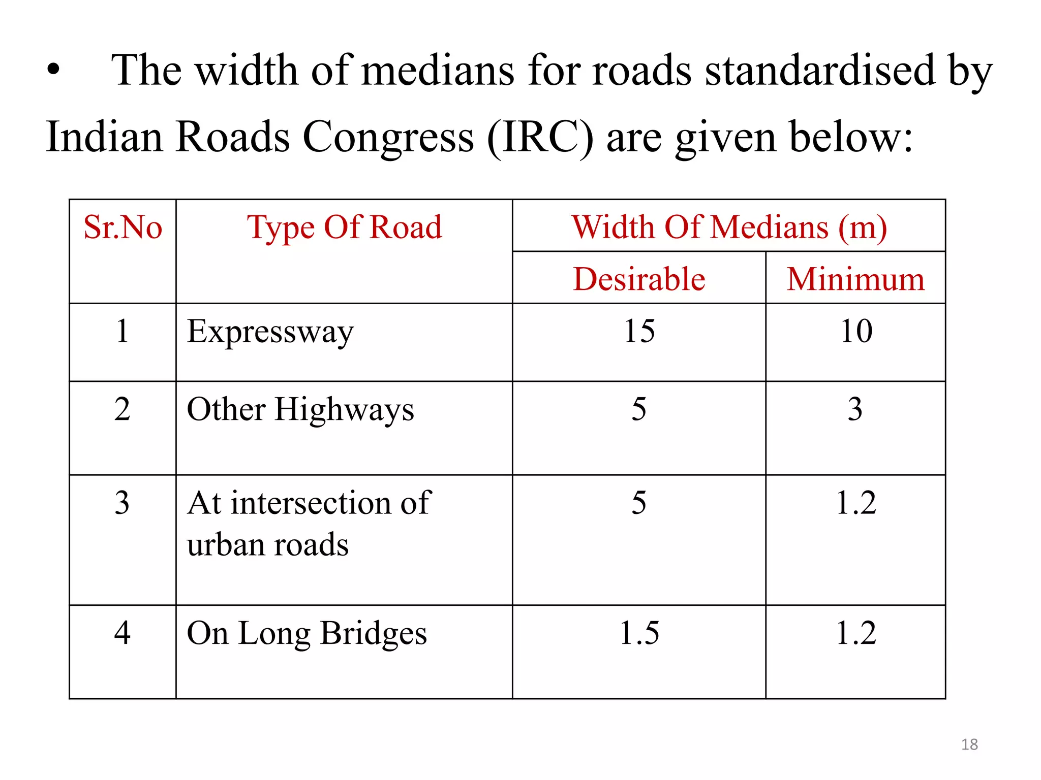
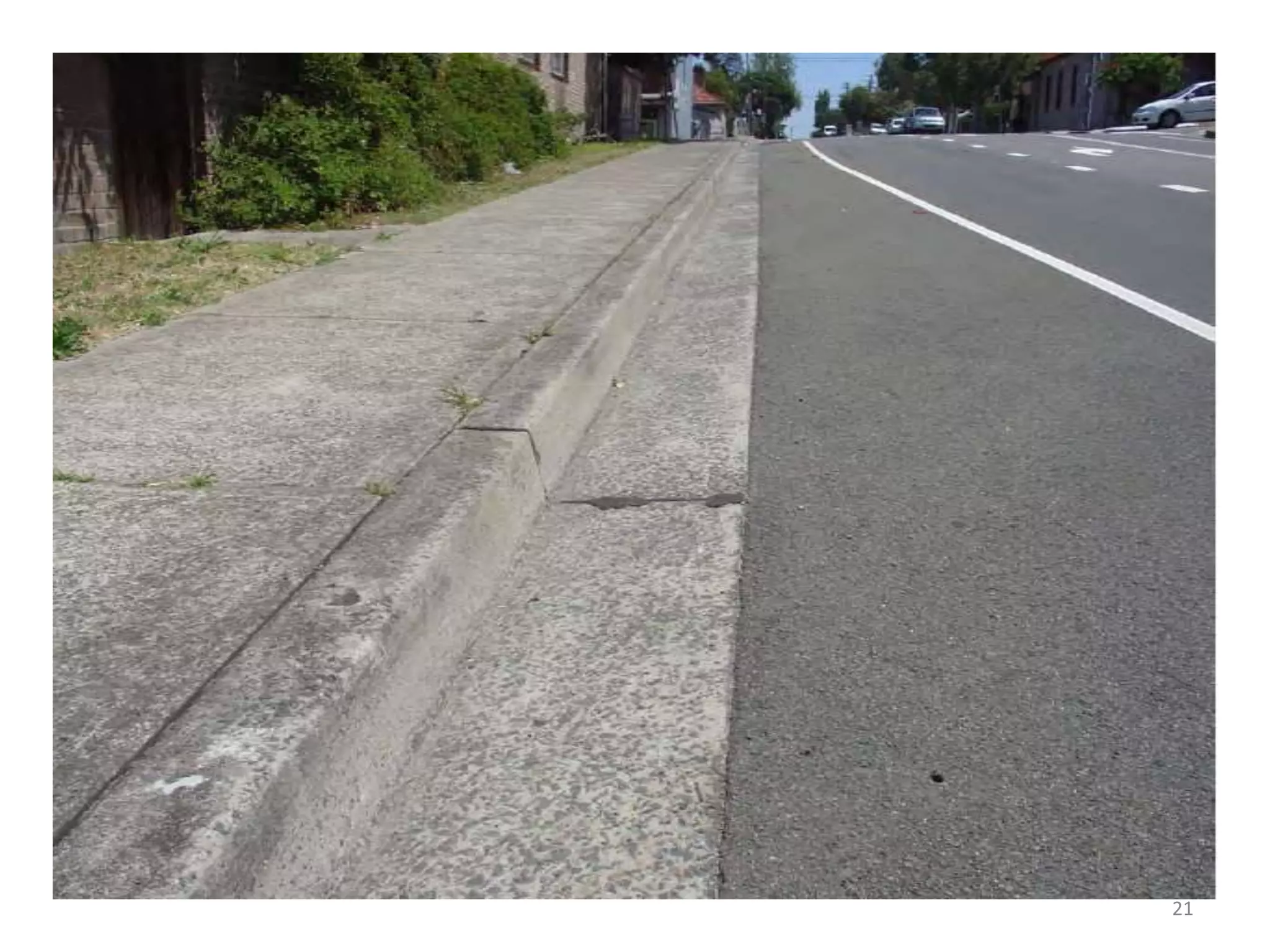
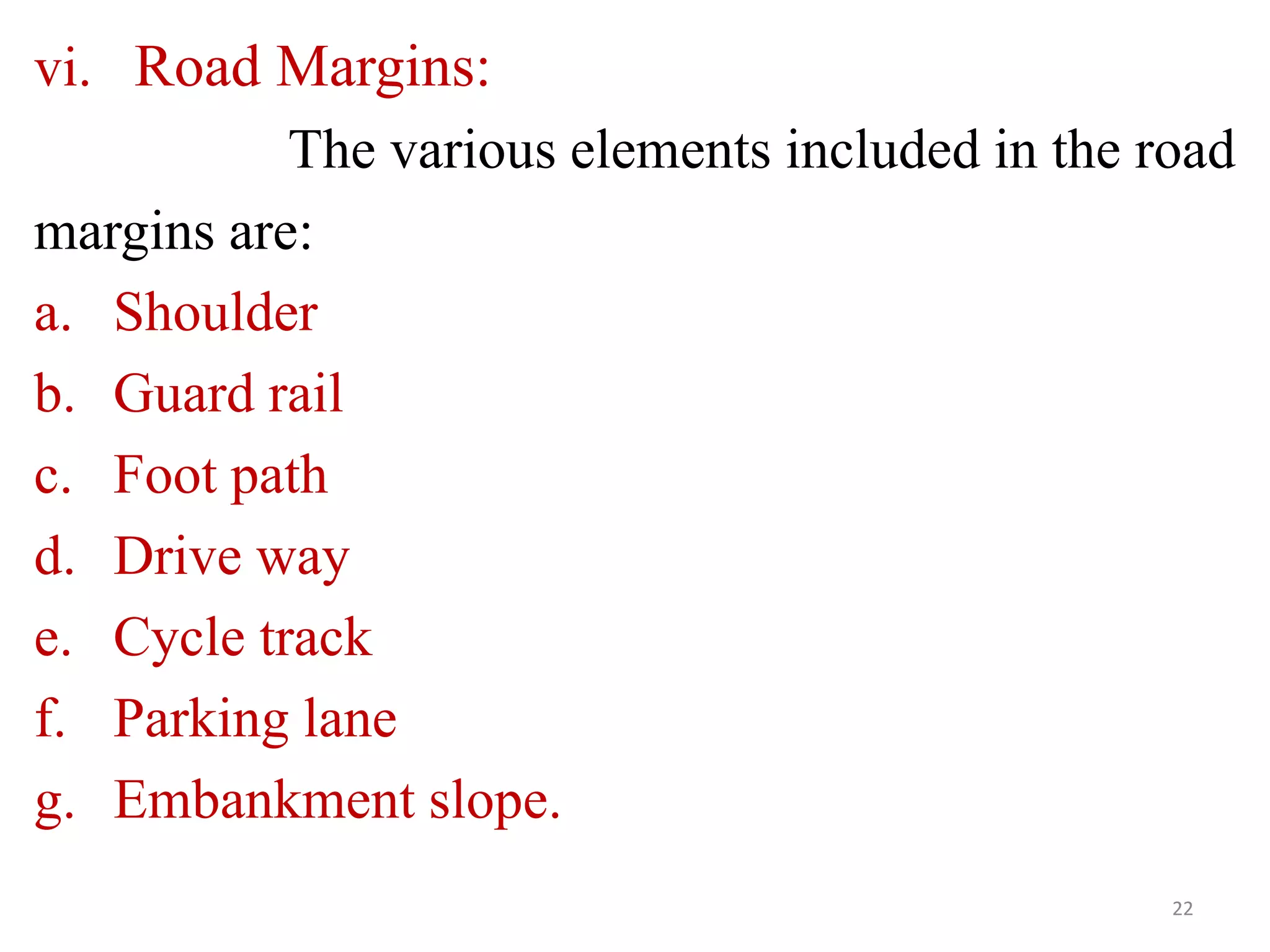
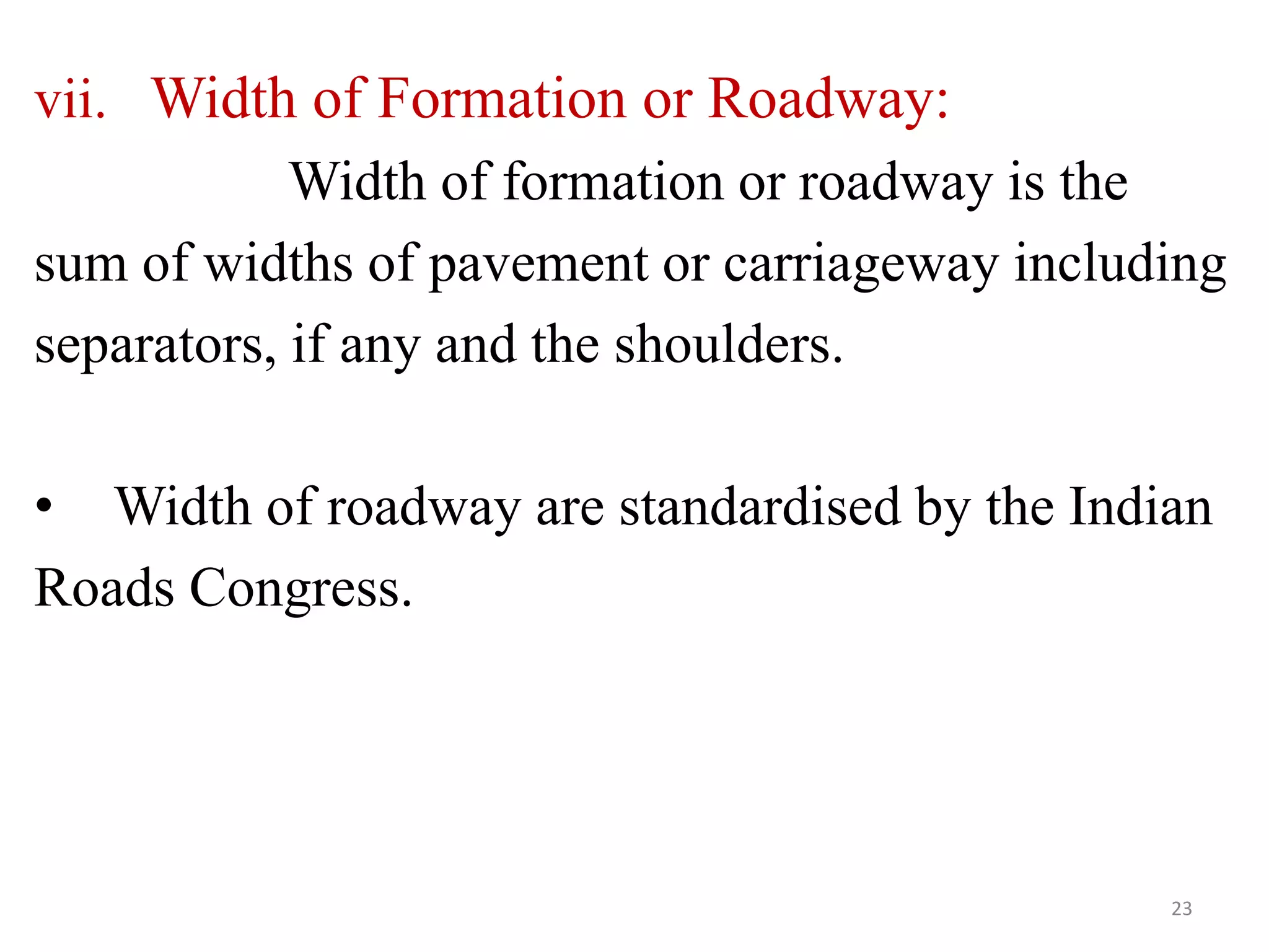
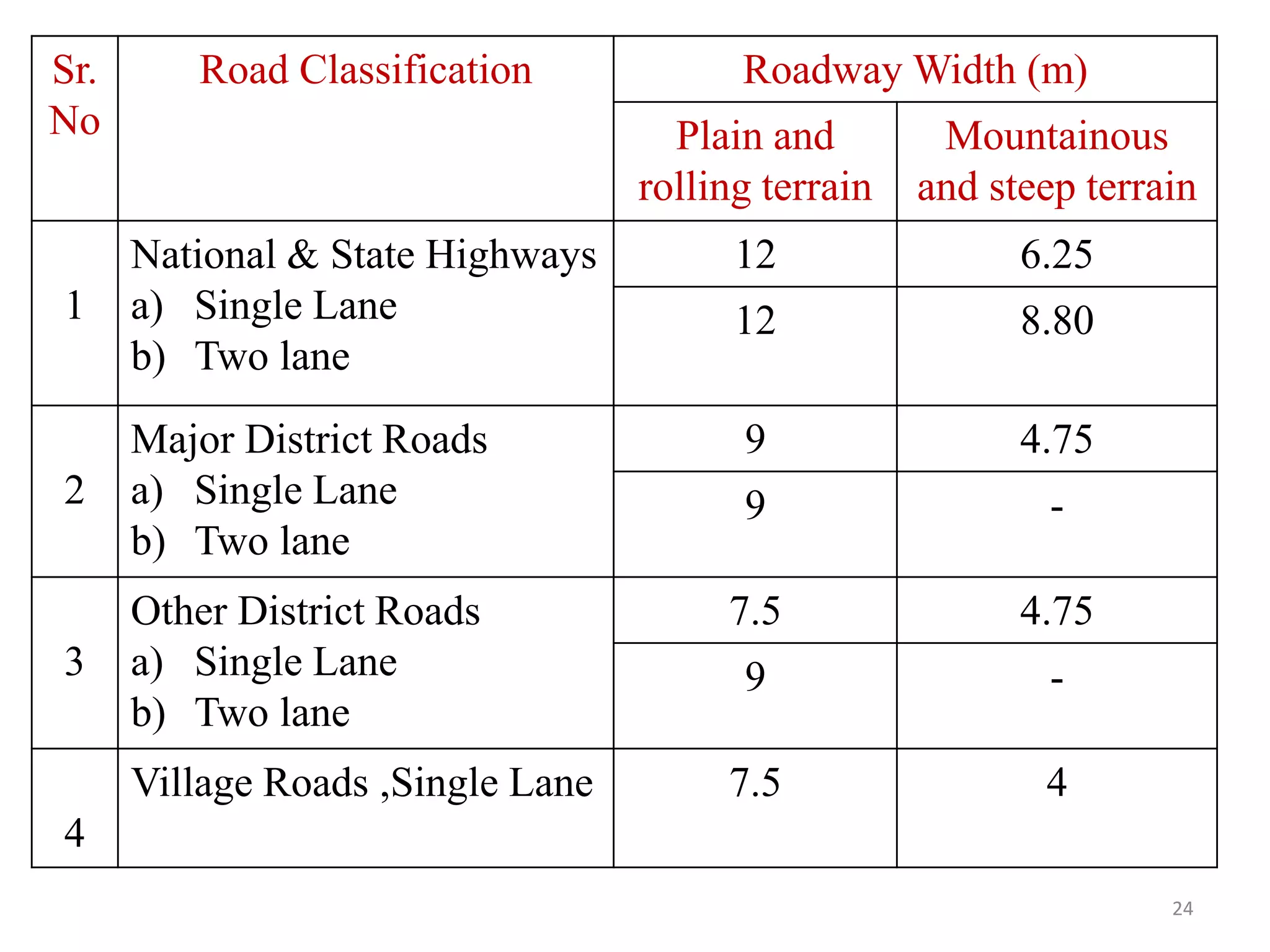


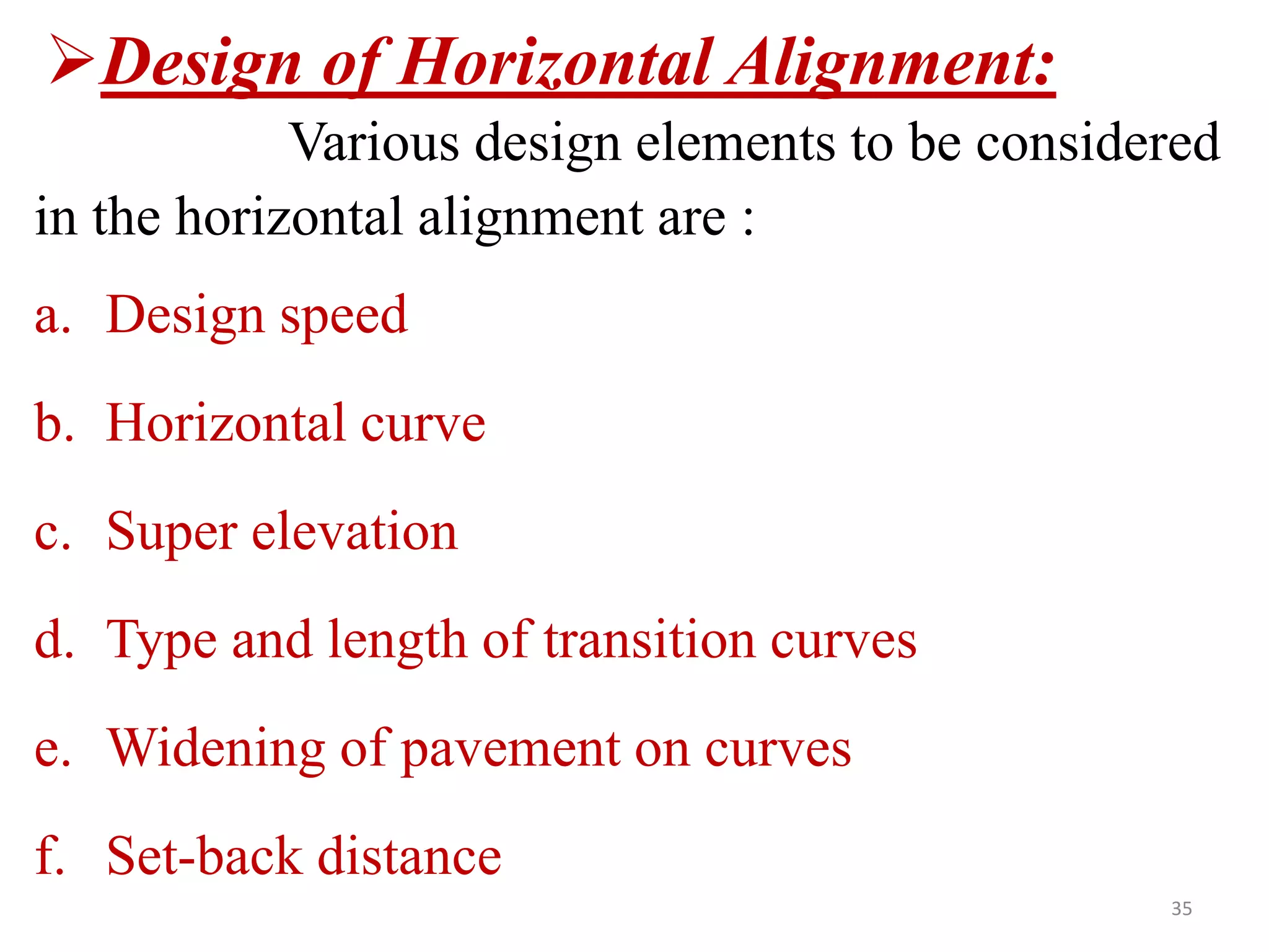


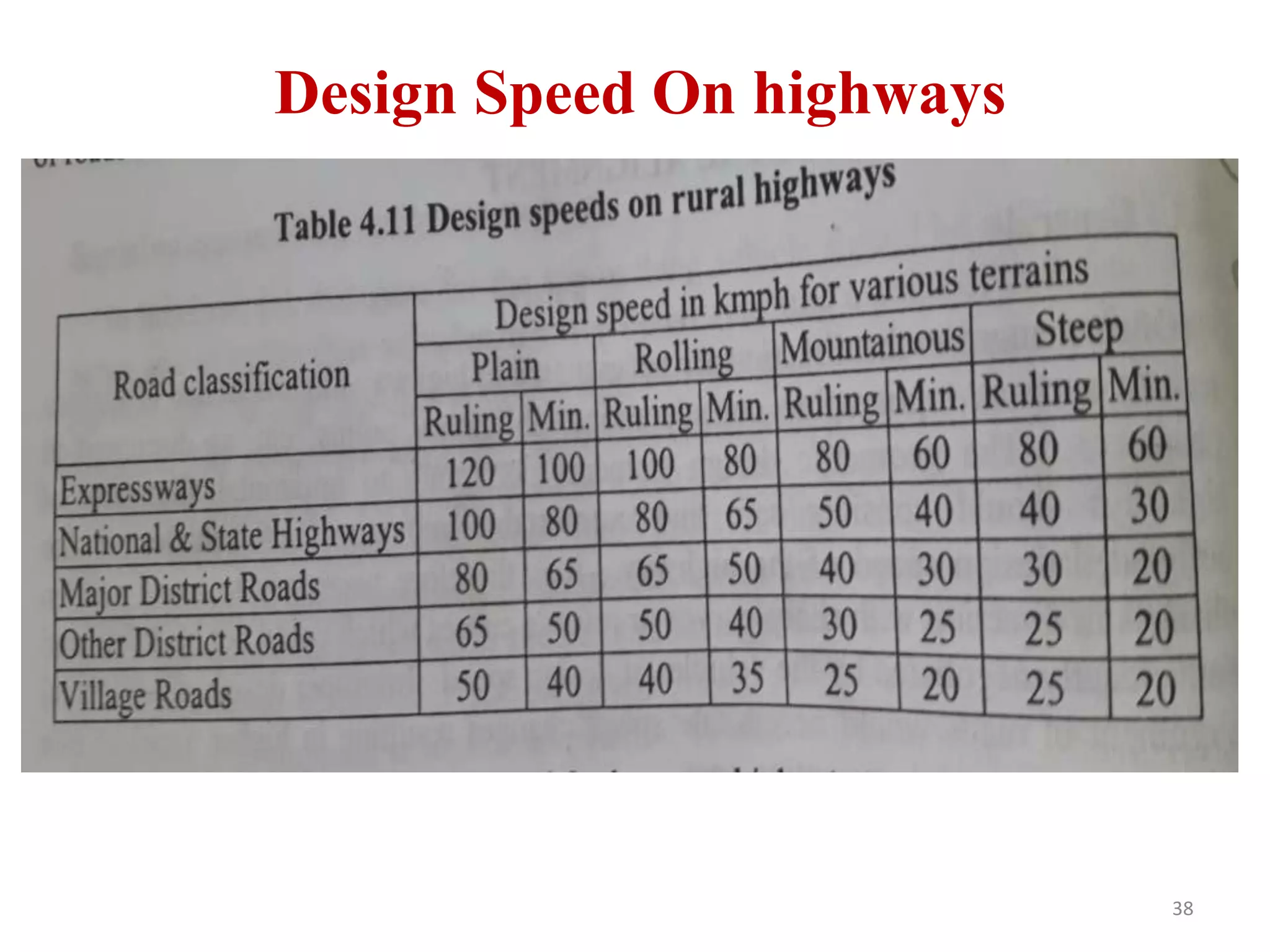
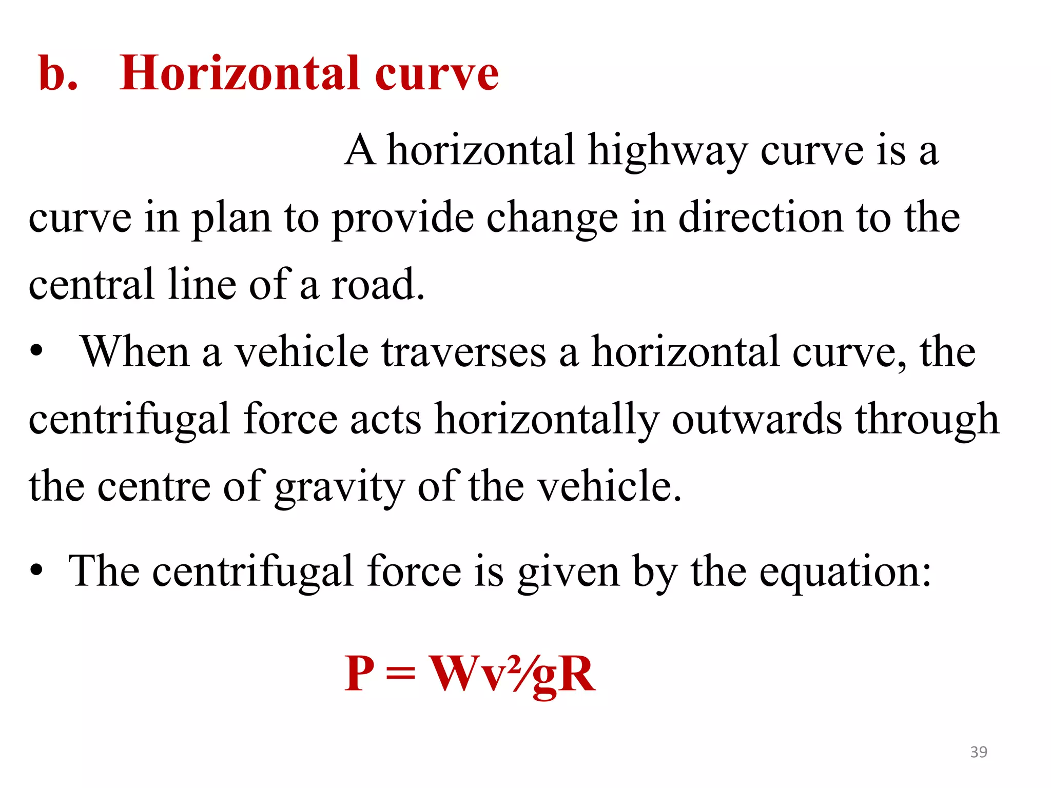


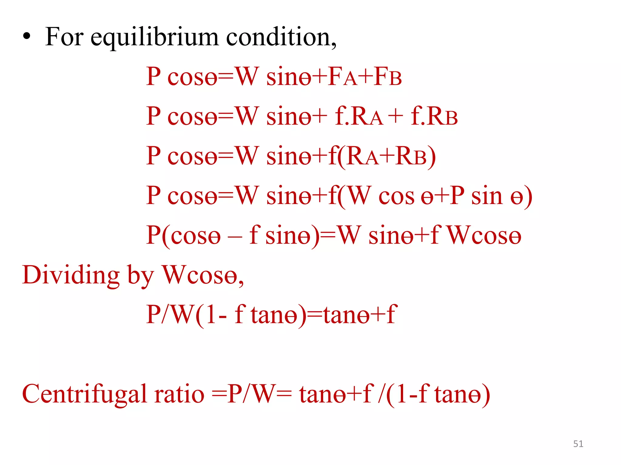
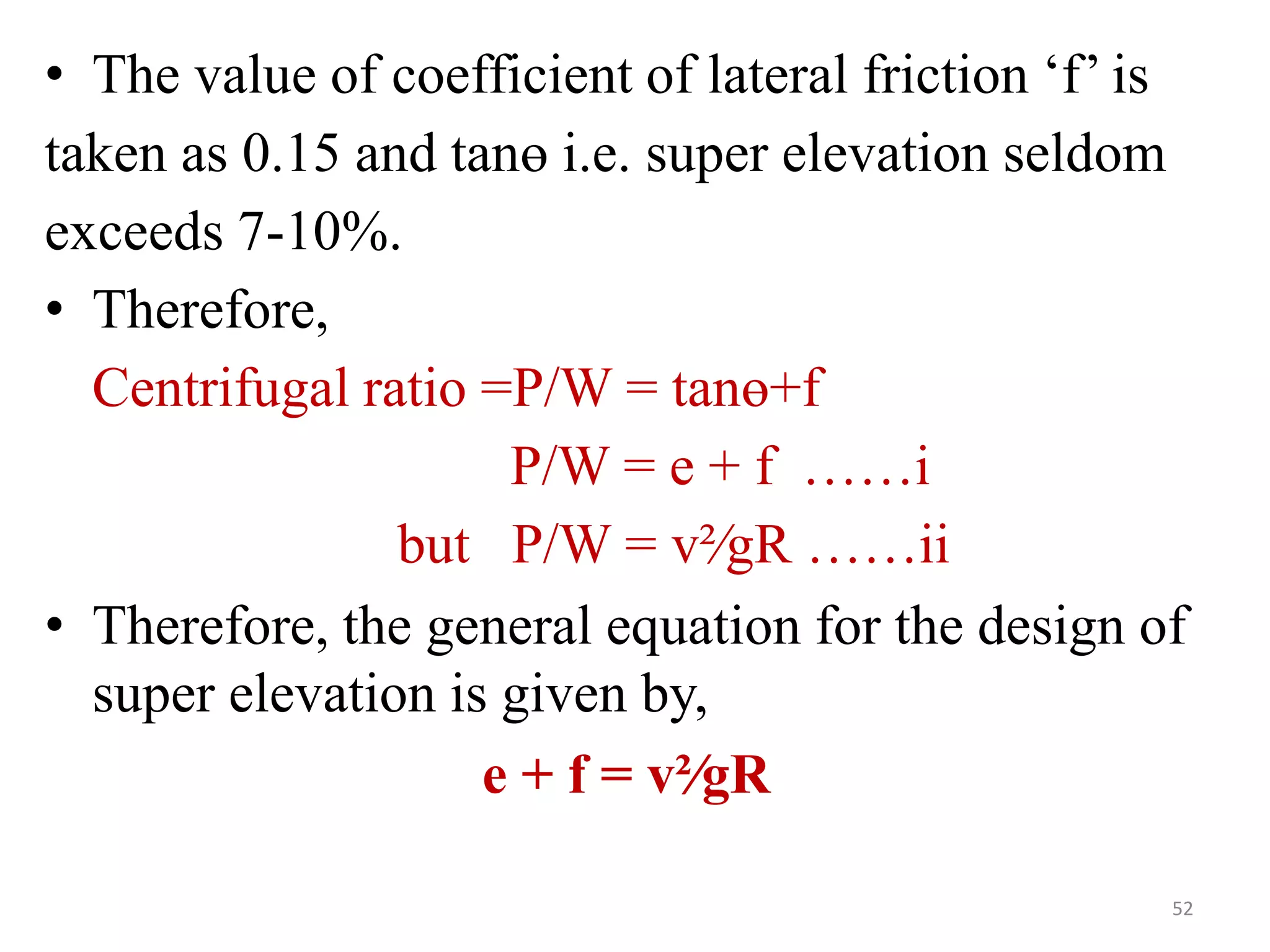
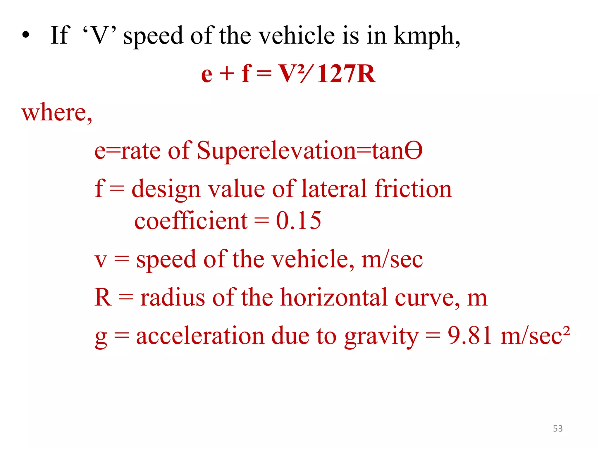
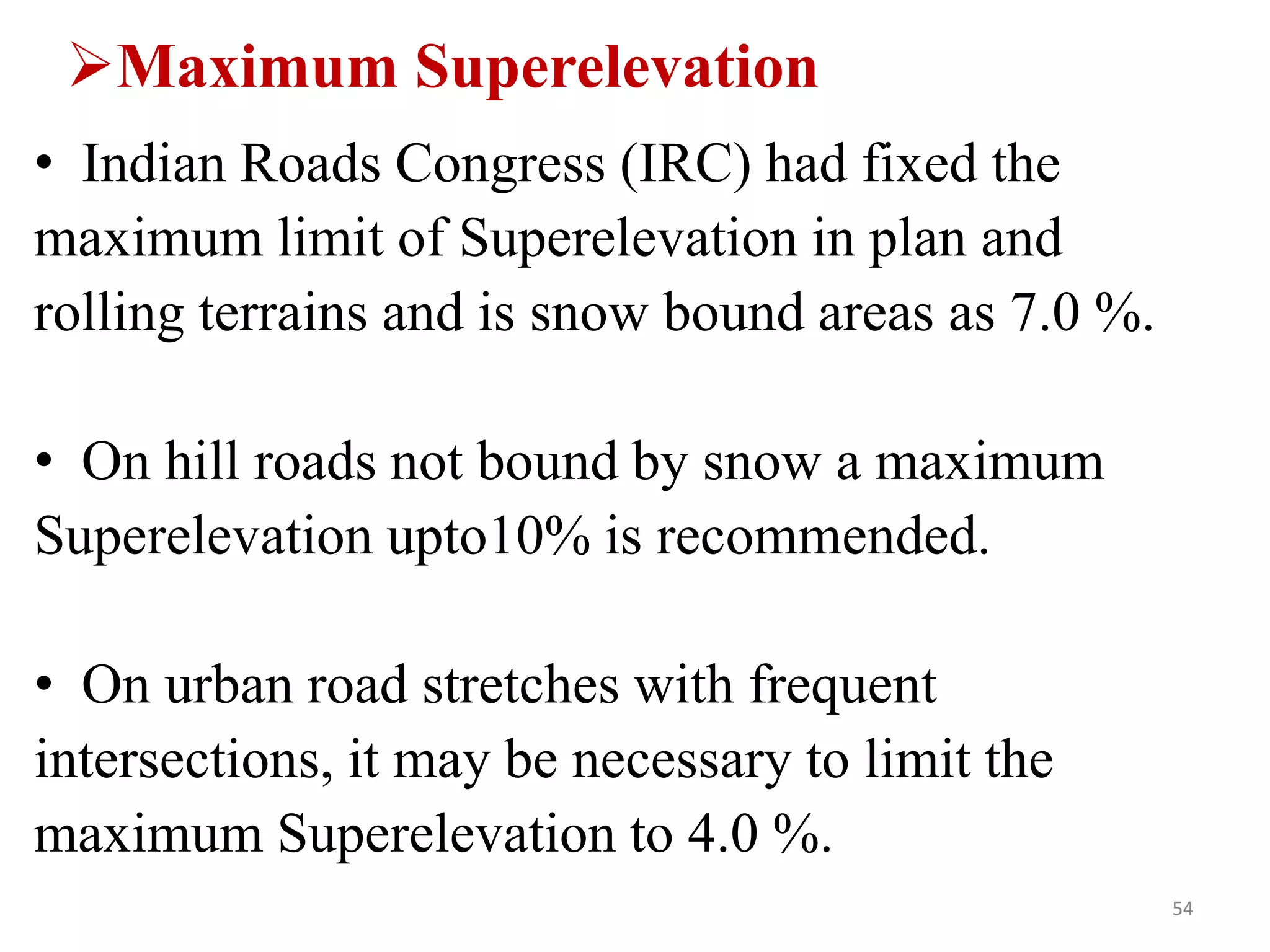


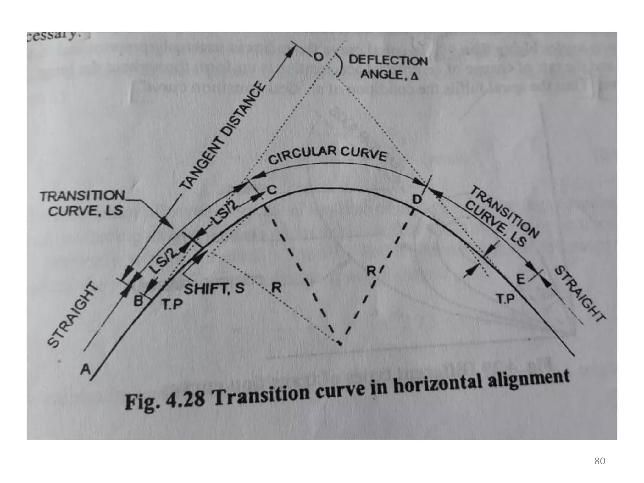


Highway geometric design deals with dimensions and layout of visible features like horizontal and vertical alignments, sight distances, and intersections. Elements of geometric design include cross section, sight distance considerations, horizontal and vertical alignments, and intersections. Cross section elements comprise pavement characteristics, carriageway width, cross slope, median/separator, kerbs, road margins, and formation width. Horizontal alignment design considers factors like design speed, horizontal curves, super elevation, transition curves, pavement widening on curves, and setback distance. Super elevation is provided to counteract centrifugal forces on curves and is limited to a maximum of 7% as per Indian standards.


