Downloaded 1,691 times
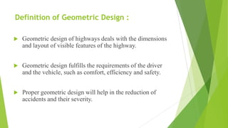
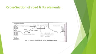


The document discusses highway geometric design, focusing on the dimensions and layout of visible highway features, which ensure driver comfort, efficiency, and safety while minimizing accidents. It covers important aspects such as road alignment, cross-sectional elements, and factors influencing design, including design speed, traffic, and environmental conditions. Additionally, it outlines components like pavement, shoulders, side slopes, and camber, which are essential for effective highway construction and maintenance.