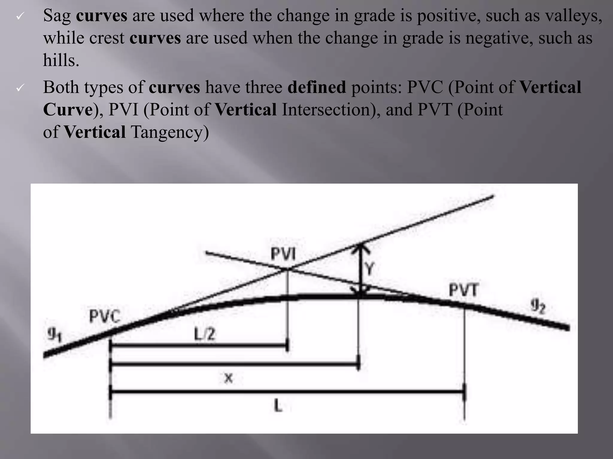
SlideShare a Scribd company logo
1 of 47
GEOMETRIC DESIGN OF HIGHWAYS
Presented by:
Vijayvenkatesh.C
CIVIL DEPARTMENT OF CIVIL ENGINEERING
FINAL YEAR.
ST.JOSEPHS COLLEGE OF ENGINEERING &
TECHNOLOGY
Rural Road Standards
 The rural roadways will not typically require curb and gutter or
sidewalk, although the County may require either or both in
unique circumstances. Widths of lanes and shoulders will vary
depending upon the specific classification and the potential traffic
volume which the roadway may carry.
 Roads carrying fewer than 200 vehicles per day need not be
paved or treated for dust control. The need for paved shoulders is
also dependent upon the level of traffic and safety.
Urban road standards
 Urban road will include 12‐foot lanes, sidewalk and curb & gutter;
arterials and collectors will also include a striped bike lane. Turn
lanes may be necessary as determined by the County.
 Since almost all of the municipalities have different right‐of‐way
cross sections adopted for their community, it makes it very
difficult for the County to match them all.
 Therefore, the philosophy was to encourage a baseline amount of
right‐of‐way reservation that could ensure the adjacent
community enough area for coordination of future roadway
improvements, until such time the community would annex the
road.
 Camber
 Width of carriage way
 Kerbs
 Road margins
 Width of formation
 Right of way
Camber
Camber or cant is the cross slope provided to raise middle
of the road surface in the transverse direction to drain off
rain water from road surface.
The objectives of providing camber are:
 Surface protection especially for gravel and bituminous
roads
 Sub-grade protection by proper drainage
 Quick drying of pavement which in turn increases safety
 Too steep slope is undesirable for it will erode the surface.
Camber is measured in 1 in n or n% (Eg. 1 in 50 or 2%)
and the value depends on the type of pavement surface
Width of carriage way
 Width of the carriage way or the width of the pavement depends
on the width of the traffic lane and number of lanes. Width of a
traffic lane depends on the width of the vehicle and the clearance.
Side clearance improves operating speed and safety.
 The maximum permissible width of a vehicle is 2.44 and the
desirable side clearance for single lane traffic is 0.68 m.
 This require minimum of lane width of 3.75 m for a single lane
road. However, the side clearance required is about 0.53 m, on
either side and 1.06 m in the center. Therefore, a two lane road
require minimum of 3.5 meter for each lane
Kerbs indicate the boundary between the carriage way and the
shoulder or islands or footpaths
 Width of formation or roadway width is the sum of the widths of
pavements or carriage way including separators and shoulders.
This does not include the extra land in formation/cutting.
Formation width= width of carriage way + width of shoulder
Right Of Way
Right of way (ROW) or land width is the width of land acquired
for the road, along its alignment. It should be adequate to
accommodate all the cross-sectional elements of the highway and
may reasonably provide for future development. ROW governed
by,
 Width of formation: It depends on the category of the highway
and width of roadway and road margins.
.
 Height of embankment or depth of cutting: It is governed by the
topography and the vertical alignment
 Side slopes of embankment or cutting: It depends on the height of
the slope, soil type etc.
 Drainage system and their size which depends on rainfall,
topography etc.
 Sight distance considerations : On curves etc. there is restriction
to the visibility on the inner side of the curve due to the presence
of some obstructions like building structures etc.
Sight distance available from a point is the actual
distance along the road surface, over which a driver from
a specified height above the carriage way has visibility of
stationary or moving objects. Three sight distance
situations are considered for design:
Stopping sight distance (SSD) or the absolute minimum
sight distance •
Intermediate sight distance (ISD) is defined as twice
SSD
Overtaking sight distance (OSD) for safe overtaking
operation
 Stopping sight distance (SSD) is the minimum sight distance
available on a highway at any spot having sufficient length to
enable the driver to stop a vehicle traveling at design speed,
safely without collision with any other obstruction.
 In highway design, sight distance atleast equal to the safe
stopping distance should be provided. The stopping sight distance
is the sum of lag distance and the braking distance.
 Lag distance is the distance the vehicle traveled during the
reaction time and is given by vt , where is v is the velocity in
m/sec2 .
 Braking distance is the distance traveled by the vehicle during
braking operation
SSD = lag distance + braking distance and
= vt+v2/2gf
Overtaking sight distance
 The overtaking sight distance is the minimum distance open to the
vision of the driver of a vehicle intending to overtake the slow
vehicle ahead safely against the traffic in the opposite direction.
 The overtaking sight distance or passing sight distance is measured
along the center line of the road over which a driver with his eye
level 1.2 m above the road surface can see the top of an object 1.2 m
above the road surface.
The factors that affect the OSD are:
 Velocities of the overtaking vehicle, overtaken vehicle and of the
vehicle coming in the opposite direction.
 Spacing between vehicles, which in-turn depends on the speed
 Skill and reaction time of the driver
 Rate of acceleration of overtaking vehicle
 Gradient of the road
Sight distance at intersections
 At intersections where two or more roads meet, visibility
should be provided for the drivers approaching the intersection
from either sides. They should be able to perceive a hazard and
stop the vehicle if required.
 Stopping sight distance for each road can be computed from
the design speed. The sight distance should be provided such
that the drivers on either side should be able to see each other
 Design of sight distance at intersections may be used on three
possible conditions:
 Enabling approaching vehicle to change the speed
 Enabling approaching vehicle to stop
 Enabling stopped vehicle to cross a main road
 When a highway changes horizontal direction, making the point
where it changes direction a point of intersection between two
straight lines is not feasible. The change in direction would be too
abrupt for the safety of modem, high-speed vehicles. It is
therefore necessary to interpose a curve between the straight lines.
The straight lines of a road are called tangents because the lines
are tangent to the curves used to change direction.
TYPES OF HORIZONTAL CURVES
 SIMPLE. The simple curve is an arc of a circle. The radius of the
circle determines the sharpness or flatness of the curve
 COMPOUND Frequently, the terrain will require the use of the
compound curve. This curve normally consists of two simple curves
joined together and curving in the same direction
 REVERSE A reverse curve consists of two simple curves joined
together, but curving in opposite direction. For safety reasons, the
use of this curve should be avoided when possible .
 SPIRAL. The spiral is a curve that has a varying radius. It is used
on railroads and most modem highways. Its purpose is to provide a
transition from the tangent to a simple curve or between simple
curves in a compound curve
The horizontal curves are, by definition, circular
curves of radius R.
 To counter-act the effect of centrifugal force and reduce the
tendency of vehicle to overturn and to skid laterally
outwards, pavement outer edge is raised with respect to inner
edge. Thus, providing a transverse slope is known as Super
elevation. It is represented by “ e ”.
 It helps rainwater drain from the road surface. Along straight
or gently curved sections, the middle of the road is normally
higher than the edges. This is called "normal crown" and
helps shed rainwater off the sides of the road.
 When a vehicle travels around a curve of constant radius at
constant speed, it exerts radially an outward force known as
“Centrifugal force”. This Centrifugal force (P) can be
represented by, P = Wv2/gR. It acts horizontally at the centre
of gravity of the vehicle and its load. The forces acting on the
vehicle are,
 the centrifugal force acting radially outwards,
 the weight of the vehicle acting vertically downwards,
 the upward reaction of the road on the vehicle.
 For equilibrium the centrifugal force must be counteracted either
by lateral friction developed between the tyre and the road
surface alone, by the inward tilt of the road surface known as
“superelevation” alone or partially by friction and partially by
superelevation while the weight of the vehicle is balanced by the
reaction of the road on the vehicle.
Limits for maximum super elevation
 According to IRC the Maximum Super elevation in Areas
 Which Are Bound by Snow fall – 7%
 Which are not bounded by Snow fall – 10%
Limits for minimum super elevation
 Minimum super elevation = camber or cross slope
 Camber: Slope provide in the transverse direction to drain off
rain water quickly is known as Camber or Cross slope. This
will also prevents slipping and skidding of vehicles.
 Transition curve is a curve in plan which is provided to change the
horizontal alignment from straight to circular curve gradually
means the radius of transition curve varies between infinity to R or
R to infinity.
 While taking a turn,the centifugal forces develop so a vehicle and
its contents are immediately subjected to centrifugal forces. More
is the speed of vehicle sharper is the curvature and thus the greater
the influence on vehicles and drivers of the change from tangent to
curve.
 When transition curves are not provided, drivers tend to
create their own transition curves by moving laterally
within their travel lane and sometimes the adjoining
lane,which is risky not only for them but also for other
road users.
Objectives for providing transition curves
1. For the gradual introduction Centrifugal force
2. To introduce super elevation gradually
3. To introduce extra widening gradually
4. To provide comfort for the driver that is to enable
smooth vehicle operation on road.
5. To enhance aesthetics of highways.
Determining length of transition curve
The length of transition curve can be calculated by 3 conditions.
 Based on rate of change of acceleration
 Based on rate of change of super elevation and extra widening
 Based in IRC empirical formula
The pavement is extra widened on the horizontal curves due to the
following reasons:
 The wheel base of the vehicles is rigid and therefore while taking the
turn, only front wheel are able to change direction. Path traveled by
the front will be different and will be at certain distance outwards
from the path traced by the inner wheel.
 There is a tendency of the driver to take the outer path at the curves to
have more sight distance visible ahead.
 While overtaking operations on horizontal curves driver will need
more spacing from the other vehicles to feel safer.
 Widening of the pavement on the horizontal curves is governed by the
following factors:
(a) Length of the wheel base
(b) Radius of the curve negotiated, R
(c) Psychological factor which depends upon the velocity of the vehicle
and the Radius of the curve.
In general extra width is provided on the horizontal curves when the
radius is less than 300 m.
Extra widening = mechanical Widening + Psychological Widening
(i) Mechanical widening :- The widening required to account for the off
tracking due to the rigidity of wheel base is called ‘Mechanical
widening
(ii) Psychological widening:At horizontal curves driveres have a tendency
to maintain a greater clearance between the vehicles than on straight
stretches of road
 Therefore an extra width of pavement is provided for
psychological reasons for greater manoeuvrability of steering
at higher speeds and to allow for the extra space
requirements for the overhangs of vehicles.
Psychological widening is therefore important in pavements
with more than one lane.
8.vertical Curves
 A vertical curve is a curve provided in vertical plane. This is
required to be provided at the meeting of grades.
Two kinds of vertical curve:
 Crest Vertical Curves + Type I and Type II
 Sag Vertical Curves + Type III and Type IV.
 Sag curves are used where the change in grade is positive, such as valleys,
while crest curves are used when the change in grade is negative, such as
hills.
 Both types of curves have three defined points: PVC (Point of Vertical
Curve), PVI (Point of Vertical Intersection), and PVT (Point
of Vertical Tangency)
 “gradient” simply refers to the steepness of a section of road. A flat road is
said to have a gradient of 0%, and a road with a higher gradient (e.g. 10%)
is steeper than a road with a lower gradient (e.g. 5%). A downhill road is
said to have a negative gradient.
Types of gradients
 Ruling gradient- This is the maximum gradient which is generally used to
design the vertical profile of highway. So it is also called as designer
gradient. Ruling gradient depends on the terrain, length of the grade,
speed, pulling power of the vehicle and the presence of the horizontal
curve. It is adopted by considering a particular speed as the design speed
and for a design vehicle with standard dimensions.
 Limiting gradient- This gradient is provided as shorter stretches in
highways. Whenever ruling gradients costs high for the hilly terrains
then limiting gradient is provided which will reduce the cost. This
gradient is adopted frequently in terrains with limited stretches.
 Exceptional gradient- These are very steeper gradients given at
unavoidable situations and they are adopted for stretches not exceeding
100m of length.
 Minimum gradient- To drain of rain water from the road minimum
gradient is needed. Generally for lateral drainage Camber is provided.
But for the longitudinal drainage along the side drains require some
slope for smooth flow of water. For concrete drains minimum gradient of
1 in 500 and open soil drains gradient of 1 in 200 is suitable.
Alignment through hilly areas is slightly different from
aligning through a flat terrain. For the purpose of efficient
and safe operation of vehicles through a hilly terrain special
care should be taken while aligning the highway. Some of
the special considerations for highway alignment through a
hilly terrain is discussed below
 Stability of the slopes: for hilly areas, the road should be
aligned through the side of the hill that is stable. The
common problem with hilly areas is that of landslides.
Excessive cutting and filling for road constructions give
way to steepening of slopes which in turn will affect the
stability.
 Hill side drainage: Adequate drainage facility should be
provided across the road. Attempts should be made to align the
roads in such a way where the number of cross drainage
structures required are minimum. This will reduce the
construction cost.
 Special geometric standards: The geometric standards
followed in hilly areas are different from those in flat terrain.
The alignment chosen should enable the ruling gradient to be
attained in minimum of the length, minimizing steep gradient,
hairpin bends and needless rise and fall.
 Ineffective rise and fall : Efforts should be made to keep
the ineffective rise and excessive fall minimum.
Some other basic requirements specially on the hill roads:
Hill roads have some other basic requirements also which
govern the alignment of the hill roads:
(1) Drainage: Drainage of the road must be kept in mind and
it must be insured that enough drainage structures can be
built on the route. As far as possible alignment must avoid the
drainage works means it must have the minimum numbers of
the drainage works.
(2) Economy: Economy is governed by the numbers of the
drainage
(3) Safety: Safety is governed by the sight distance, super-
elevation and the design radius of the curves. It must be
kept in mind that gradient must be kept below the ruling
gradient. In hill roads special attention must be given to
the side slopes, and thorough geological surveys must be
carried out to ensure the safety while construction as well
as while traffic movement.
(4) Minimum resisting length: The un-necessary rise and
fall of the gradient must be minimized to reduce the cost
and length of road.
e works, cutting filling and the gradient.
A hairpin turn (also hairpin bend, hairpin corner, etc.), named
for its resemblance to a hairpin/bobby pin, is a bend in
a road with a very acute inner angle, making it necessary for an
oncoming vehicle to turn almost 180° to continue on the road
Geometrical design of highways

More Related Content

What's hot

Introduction to highway engineering
Introduction to highway engineeringIntroduction to highway engineering
Introduction to highway engineeringAavani Thampi
 
Geometric design of highway
Geometric design of  highwayGeometric design of  highway
Geometric design of highwayPratikShinde113
 
GEOMETRIC DESIGN OF HIGHWAY
GEOMETRIC DESIGN OF HIGHWAYGEOMETRIC DESIGN OF HIGHWAY
GEOMETRIC DESIGN OF HIGHWAYreemajadwani
 
Transition curve and Superelevation
Transition curve and SuperelevationTransition curve and Superelevation
Transition curve and SuperelevationMir Zafarullah
 
2.2 HIGHWAY TRANSPORTATION : HIGHWAY GEOMETRIC DESIGN (TRE) 3150611 GTU
2.2 HIGHWAY TRANSPORTATION : HIGHWAY GEOMETRIC DESIGN (TRE) 3150611 GTU2.2 HIGHWAY TRANSPORTATION : HIGHWAY GEOMETRIC DESIGN (TRE) 3150611 GTU
2.2 HIGHWAY TRANSPORTATION : HIGHWAY GEOMETRIC DESIGN (TRE) 3150611 GTUVATSAL PATEL
 
Geometric Design - Horizontal and vertical curves
Geometric Design - Horizontal and vertical curvesGeometric Design - Horizontal and vertical curves
Geometric Design - Horizontal and vertical curvessachin dass
 
Transportation Engineering I
Transportation Engineering ITransportation Engineering I
Transportation Engineering IShradhesh Marve
 
Highway geometric design
Highway geometric designHighway geometric design
Highway geometric designNikunj Hindocha
 
Highway Horizontal Alignment
Highway Horizontal AlignmentHighway Horizontal Alignment
Highway Horizontal AlignmentAkshathaBhandary
 
Horizontal curves PRESENTATION
Horizontal curves PRESENTATIONHorizontal curves PRESENTATION
Horizontal curves PRESENTATIONGHULAM RASOOL
 
Unit 1:- HIGHWAY DEVELOPMENT AND PLANNING
Unit 1:- HIGHWAY DEVELOPMENT AND PLANNINGUnit 1:- HIGHWAY DEVELOPMENT AND PLANNING
Unit 1:- HIGHWAY DEVELOPMENT AND PLANNINGRNRANGANATH
 

What's hot (20)

Introduction to highway engineering
Introduction to highway engineeringIntroduction to highway engineering
Introduction to highway engineering
 
Unit 1
Unit 1Unit 1
Unit 1
 
Vertical alignment
Vertical alignmentVertical alignment
Vertical alignment
 
Geometric design of highway
Geometric design of  highwayGeometric design of  highway
Geometric design of highway
 
GEOMETRIC DESIGN OF HIGHWAY
GEOMETRIC DESIGN OF HIGHWAYGEOMETRIC DESIGN OF HIGHWAY
GEOMETRIC DESIGN OF HIGHWAY
 
Transition curve and Superelevation
Transition curve and SuperelevationTransition curve and Superelevation
Transition curve and Superelevation
 
Intersection designs ppt
Intersection designs pptIntersection designs ppt
Intersection designs ppt
 
Unit 2
Unit 2Unit 2
Unit 2
 
2.2 HIGHWAY TRANSPORTATION : HIGHWAY GEOMETRIC DESIGN (TRE) 3150611 GTU
2.2 HIGHWAY TRANSPORTATION : HIGHWAY GEOMETRIC DESIGN (TRE) 3150611 GTU2.2 HIGHWAY TRANSPORTATION : HIGHWAY GEOMETRIC DESIGN (TRE) 3150611 GTU
2.2 HIGHWAY TRANSPORTATION : HIGHWAY GEOMETRIC DESIGN (TRE) 3150611 GTU
 
Geometric Design - Horizontal and vertical curves
Geometric Design - Horizontal and vertical curvesGeometric Design - Horizontal and vertical curves
Geometric Design - Horizontal and vertical curves
 
Road geometrics
Road geometricsRoad geometrics
Road geometrics
 
Transportation Engineering I
Transportation Engineering ITransportation Engineering I
Transportation Engineering I
 
Chapter 3 junction design
Chapter 3 junction designChapter 3 junction design
Chapter 3 junction design
 
Highway geometric design
Highway geometric designHighway geometric design
Highway geometric design
 
Highway Horizontal Alignment
Highway Horizontal AlignmentHighway Horizontal Alignment
Highway Horizontal Alignment
 
Highway planning and alignment
Highway planning and alignmentHighway planning and alignment
Highway planning and alignment
 
Horizontal curves PRESENTATION
Horizontal curves PRESENTATIONHorizontal curves PRESENTATION
Horizontal curves PRESENTATION
 
Unit 3
Unit 3Unit 3
Unit 3
 
PERMANANT WAY
PERMANANT WAYPERMANANT WAY
PERMANANT WAY
 
Unit 1:- HIGHWAY DEVELOPMENT AND PLANNING
Unit 1:- HIGHWAY DEVELOPMENT AND PLANNINGUnit 1:- HIGHWAY DEVELOPMENT AND PLANNING
Unit 1:- HIGHWAY DEVELOPMENT AND PLANNING
 

Similar to Geometrical design of highways

Cross section of road and sight distance
Cross section of road and sight distanceCross section of road and sight distance
Cross section of road and sight distanceSarvagya Tripathi
 
Geometric design of roads - Highways - Copy.docx
Geometric design of roads - Highways - Copy.docxGeometric design of roads - Highways - Copy.docx
Geometric design of roads - Highways - Copy.docxsydneyaugust1
 
Geometric design of roads - Highways.docx
Geometric design of roads - Highways.docxGeometric design of roads - Highways.docx
Geometric design of roads - Highways.docxsydneyaugust1
 
Highway engineering PPT
Highway engineering PPTHighway engineering PPT
Highway engineering PPTKavin Raval
 
Highway Cross-sectional Elements
Highway Cross-sectional ElementsHighway Cross-sectional Elements
Highway Cross-sectional ElementsAkshathaBhandary
 
Unit- 3 Highway Geometric design
Unit- 3 Highway Geometric designUnit- 3 Highway Geometric design
Unit- 3 Highway Geometric designRNRANGANATH
 
5. TRAFFIC GEOMETRICS (TE) 2170613 GTU
5. TRAFFIC GEOMETRICS (TE) 2170613 GTU5. TRAFFIC GEOMETRICS (TE) 2170613 GTU
5. TRAFFIC GEOMETRICS (TE) 2170613 GTUVATSAL PATEL
 
Cross Sectional Elements PPT.pdf
Cross Sectional Elements PPT.pdfCross Sectional Elements PPT.pdf
Cross Sectional Elements PPT.pdfDhananjayM6
 
Designing the highway 2
Designing the highway 2Designing the highway 2
Designing the highway 2Rron de Guzman
 
intro to alignment.pptx
intro to alignment.pptxintro to alignment.pptx
intro to alignment.pptxCIVILSWATHI
 
ch. 5 traffic Island.pptx
ch. 5 traffic Island.pptxch. 5 traffic Island.pptx
ch. 5 traffic Island.pptxMehulChavda10
 
1 geometric design elements of road by malyar talash
1 geometric design elements of road by malyar talash1 geometric design elements of road by malyar talash
1 geometric design elements of road by malyar talashMalyar Talash
 
geometric design ppt unit 3 (1).ppt
geometric design ppt unit 3 (1).pptgeometric design ppt unit 3 (1).ppt
geometric design ppt unit 3 (1).pptGate20241
 
Transportation engineering 1
Transportation engineering   1Transportation engineering   1
Transportation engineering 1R VIJAYAKUMAR
 

Similar to Geometrical design of highways (20)

Cross section of road and sight distance
Cross section of road and sight distanceCross section of road and sight distance
Cross section of road and sight distance
 
Geometric design of roads - Highways - Copy.docx
Geometric design of roads - Highways - Copy.docxGeometric design of roads - Highways - Copy.docx
Geometric design of roads - Highways - Copy.docx
 
Geometric design of roads - Highways.docx
Geometric design of roads - Highways.docxGeometric design of roads - Highways.docx
Geometric design of roads - Highways.docx
 
Highway engineering PPT
Highway engineering PPTHighway engineering PPT
Highway engineering PPT
 
Highway geometric design
Highway geometric designHighway geometric design
Highway geometric design
 
Intersection designs
Intersection designs Intersection designs
Intersection designs
 
Highway Cross-sectional Elements
Highway Cross-sectional ElementsHighway Cross-sectional Elements
Highway Cross-sectional Elements
 
Unit- 3 Highway Geometric design
Unit- 3 Highway Geometric designUnit- 3 Highway Geometric design
Unit- 3 Highway Geometric design
 
5. TRAFFIC GEOMETRICS (TE) 2170613 GTU
5. TRAFFIC GEOMETRICS (TE) 2170613 GTU5. TRAFFIC GEOMETRICS (TE) 2170613 GTU
5. TRAFFIC GEOMETRICS (TE) 2170613 GTU
 
Unit_II ARP.pptx
Unit_II ARP.pptxUnit_II ARP.pptx
Unit_II ARP.pptx
 
Cross Sectional Elements PPT.pdf
Cross Sectional Elements PPT.pdfCross Sectional Elements PPT.pdf
Cross Sectional Elements PPT.pdf
 
Designing the highway 2
Designing the highway 2Designing the highway 2
Designing the highway 2
 
Traffic geometrics
Traffic geometricsTraffic geometrics
Traffic geometrics
 
intro to alignment.pptx
intro to alignment.pptxintro to alignment.pptx
intro to alignment.pptx
 
R E T 565construction Technology Infrastructure
R E T 565construction Technology InfrastructureR E T 565construction Technology Infrastructure
R E T 565construction Technology Infrastructure
 
Construction Technology
Construction TechnologyConstruction Technology
Construction Technology
 
ch. 5 traffic Island.pptx
ch. 5 traffic Island.pptxch. 5 traffic Island.pptx
ch. 5 traffic Island.pptx
 
1 geometric design elements of road by malyar talash
1 geometric design elements of road by malyar talash1 geometric design elements of road by malyar talash
1 geometric design elements of road by malyar talash
 
geometric design ppt unit 3 (1).ppt
geometric design ppt unit 3 (1).pptgeometric design ppt unit 3 (1).ppt
geometric design ppt unit 3 (1).ppt
 
Transportation engineering 1
Transportation engineering   1Transportation engineering   1
Transportation engineering 1
 

Recently uploaded

Heart Disease Prediction using machine learning.pptx
Heart Disease Prediction using machine learning.pptxHeart Disease Prediction using machine learning.pptx
Heart Disease Prediction using machine learning.pptxPoojaBan
 
VIP Call Girls Service Kondapur Hyderabad Call +91-8250192130
VIP Call Girls Service Kondapur Hyderabad Call +91-8250192130VIP Call Girls Service Kondapur Hyderabad Call +91-8250192130
VIP Call Girls Service Kondapur Hyderabad Call +91-8250192130Suhani Kapoor
 
Call Girls Delhi {Jodhpur} 9711199012 high profile service
Call Girls Delhi {Jodhpur} 9711199012 high profile serviceCall Girls Delhi {Jodhpur} 9711199012 high profile service
Call Girls Delhi {Jodhpur} 9711199012 high profile servicerehmti665
 
High Profile Call Girls Nagpur Meera Call 7001035870 Meet With Nagpur Escorts
High Profile Call Girls Nagpur Meera Call 7001035870 Meet With Nagpur EscortsHigh Profile Call Girls Nagpur Meera Call 7001035870 Meet With Nagpur Escorts
High Profile Call Girls Nagpur Meera Call 7001035870 Meet With Nagpur EscortsCall Girls in Nagpur High Profile
 
Microscopic Analysis of Ceramic Materials.pptx
Microscopic Analysis of Ceramic Materials.pptxMicroscopic Analysis of Ceramic Materials.pptx
Microscopic Analysis of Ceramic Materials.pptxpurnimasatapathy1234
 
Current Transformer Drawing and GTP for MSETCL
Current Transformer Drawing and GTP for MSETCLCurrent Transformer Drawing and GTP for MSETCL
Current Transformer Drawing and GTP for MSETCLDeelipZope
 
Gurgaon ✡️9711147426✨Call In girls Gurgaon Sector 51 escort service
Gurgaon ✡️9711147426✨Call In girls Gurgaon Sector 51 escort serviceGurgaon ✡️9711147426✨Call In girls Gurgaon Sector 51 escort service
Gurgaon ✡️9711147426✨Call In girls Gurgaon Sector 51 escort servicejennyeacort
 
microprocessor 8085 and its interfacing
microprocessor 8085  and its interfacingmicroprocessor 8085  and its interfacing
microprocessor 8085 and its interfacingjaychoudhary37
 
ZXCTN 5804 / ZTE PTN / ZTE POTN / ZTE 5804 PTN / ZTE POTN 5804 ( 100/200 GE Z...
ZXCTN 5804 / ZTE PTN / ZTE POTN / ZTE 5804 PTN / ZTE POTN 5804 ( 100/200 GE Z...ZXCTN 5804 / ZTE PTN / ZTE POTN / ZTE 5804 PTN / ZTE POTN 5804 ( 100/200 GE Z...
ZXCTN 5804 / ZTE PTN / ZTE POTN / ZTE 5804 PTN / ZTE POTN 5804 ( 100/200 GE Z...ZTE
 
VIP Call Girls Service Hitech City Hyderabad Call +91-8250192130
VIP Call Girls Service Hitech City Hyderabad Call +91-8250192130VIP Call Girls Service Hitech City Hyderabad Call +91-8250192130
VIP Call Girls Service Hitech City Hyderabad Call +91-8250192130Suhani Kapoor
 
Sheet Pile Wall Design and Construction: A Practical Guide for Civil Engineer...
Sheet Pile Wall Design and Construction: A Practical Guide for Civil Engineer...Sheet Pile Wall Design and Construction: A Practical Guide for Civil Engineer...
Sheet Pile Wall Design and Construction: A Practical Guide for Civil Engineer...Dr.Costas Sachpazis
 
Software and Systems Engineering Standards: Verification and Validation of Sy...
Software and Systems Engineering Standards: Verification and Validation of Sy...Software and Systems Engineering Standards: Verification and Validation of Sy...
Software and Systems Engineering Standards: Verification and Validation of Sy...VICTOR MAESTRE RAMIREZ
 
SPICE PARK APR2024 ( 6,793 SPICE Models )
SPICE PARK APR2024 ( 6,793 SPICE Models )SPICE PARK APR2024 ( 6,793 SPICE Models )
SPICE PARK APR2024 ( 6,793 SPICE Models )Tsuyoshi Horigome
 
Call Girls Narol 7397865700 Independent Call Girls
Call Girls Narol 7397865700 Independent Call GirlsCall Girls Narol 7397865700 Independent Call Girls
Call Girls Narol 7397865700 Independent Call Girlsssuser7cb4ff
 
Introduction to Microprocesso programming and interfacing.pptx
Introduction to Microprocesso programming and interfacing.pptxIntroduction to Microprocesso programming and interfacing.pptx
Introduction to Microprocesso programming and interfacing.pptxvipinkmenon1
 
OSVC_Meta-Data based Simulation Automation to overcome Verification Challenge...
OSVC_Meta-Data based Simulation Automation to overcome Verification Challenge...OSVC_Meta-Data based Simulation Automation to overcome Verification Challenge...
OSVC_Meta-Data based Simulation Automation to overcome Verification Challenge...Soham Mondal
 
(MEERA) Dapodi Call Girls Just Call 7001035870 [ Cash on Delivery ] Pune Escorts
(MEERA) Dapodi Call Girls Just Call 7001035870 [ Cash on Delivery ] Pune Escorts(MEERA) Dapodi Call Girls Just Call 7001035870 [ Cash on Delivery ] Pune Escorts
(MEERA) Dapodi Call Girls Just Call 7001035870 [ Cash on Delivery ] Pune Escortsranjana rawat
 

Recently uploaded (20)

Heart Disease Prediction using machine learning.pptx
Heart Disease Prediction using machine learning.pptxHeart Disease Prediction using machine learning.pptx
Heart Disease Prediction using machine learning.pptx
 
🔝9953056974🔝!!-YOUNG call girls in Rajendra Nagar Escort rvice Shot 2000 nigh...
🔝9953056974🔝!!-YOUNG call girls in Rajendra Nagar Escort rvice Shot 2000 nigh...🔝9953056974🔝!!-YOUNG call girls in Rajendra Nagar Escort rvice Shot 2000 nigh...
🔝9953056974🔝!!-YOUNG call girls in Rajendra Nagar Escort rvice Shot 2000 nigh...
 
VIP Call Girls Service Kondapur Hyderabad Call +91-8250192130
VIP Call Girls Service Kondapur Hyderabad Call +91-8250192130VIP Call Girls Service Kondapur Hyderabad Call +91-8250192130
VIP Call Girls Service Kondapur Hyderabad Call +91-8250192130
 
Call Girls Delhi {Jodhpur} 9711199012 high profile service
Call Girls Delhi {Jodhpur} 9711199012 high profile serviceCall Girls Delhi {Jodhpur} 9711199012 high profile service
Call Girls Delhi {Jodhpur} 9711199012 high profile service
 
Call Us -/9953056974- Call Girls In Vikaspuri-/- Delhi NCR
Call Us -/9953056974- Call Girls In Vikaspuri-/- Delhi NCRCall Us -/9953056974- Call Girls In Vikaspuri-/- Delhi NCR
Call Us -/9953056974- Call Girls In Vikaspuri-/- Delhi NCR
 
High Profile Call Girls Nagpur Meera Call 7001035870 Meet With Nagpur Escorts
High Profile Call Girls Nagpur Meera Call 7001035870 Meet With Nagpur EscortsHigh Profile Call Girls Nagpur Meera Call 7001035870 Meet With Nagpur Escorts
High Profile Call Girls Nagpur Meera Call 7001035870 Meet With Nagpur Escorts
 
Microscopic Analysis of Ceramic Materials.pptx
Microscopic Analysis of Ceramic Materials.pptxMicroscopic Analysis of Ceramic Materials.pptx
Microscopic Analysis of Ceramic Materials.pptx
 
Current Transformer Drawing and GTP for MSETCL
Current Transformer Drawing and GTP for MSETCLCurrent Transformer Drawing and GTP for MSETCL
Current Transformer Drawing and GTP for MSETCL
 
Gurgaon ✡️9711147426✨Call In girls Gurgaon Sector 51 escort service
Gurgaon ✡️9711147426✨Call In girls Gurgaon Sector 51 escort serviceGurgaon ✡️9711147426✨Call In girls Gurgaon Sector 51 escort service
Gurgaon ✡️9711147426✨Call In girls Gurgaon Sector 51 escort service
 
microprocessor 8085 and its interfacing
microprocessor 8085  and its interfacingmicroprocessor 8085  and its interfacing
microprocessor 8085 and its interfacing
 
ZXCTN 5804 / ZTE PTN / ZTE POTN / ZTE 5804 PTN / ZTE POTN 5804 ( 100/200 GE Z...
ZXCTN 5804 / ZTE PTN / ZTE POTN / ZTE 5804 PTN / ZTE POTN 5804 ( 100/200 GE Z...ZXCTN 5804 / ZTE PTN / ZTE POTN / ZTE 5804 PTN / ZTE POTN 5804 ( 100/200 GE Z...
ZXCTN 5804 / ZTE PTN / ZTE POTN / ZTE 5804 PTN / ZTE POTN 5804 ( 100/200 GE Z...
 
VIP Call Girls Service Hitech City Hyderabad Call +91-8250192130
VIP Call Girls Service Hitech City Hyderabad Call +91-8250192130VIP Call Girls Service Hitech City Hyderabad Call +91-8250192130
VIP Call Girls Service Hitech City Hyderabad Call +91-8250192130
 
9953056974 Call Girls In South Ex, Escorts (Delhi) NCR.pdf
9953056974 Call Girls In South Ex, Escorts (Delhi) NCR.pdf9953056974 Call Girls In South Ex, Escorts (Delhi) NCR.pdf
9953056974 Call Girls In South Ex, Escorts (Delhi) NCR.pdf
 
Sheet Pile Wall Design and Construction: A Practical Guide for Civil Engineer...
Sheet Pile Wall Design and Construction: A Practical Guide for Civil Engineer...Sheet Pile Wall Design and Construction: A Practical Guide for Civil Engineer...
Sheet Pile Wall Design and Construction: A Practical Guide for Civil Engineer...
 
Software and Systems Engineering Standards: Verification and Validation of Sy...
Software and Systems Engineering Standards: Verification and Validation of Sy...Software and Systems Engineering Standards: Verification and Validation of Sy...
Software and Systems Engineering Standards: Verification and Validation of Sy...
 
SPICE PARK APR2024 ( 6,793 SPICE Models )
SPICE PARK APR2024 ( 6,793 SPICE Models )SPICE PARK APR2024 ( 6,793 SPICE Models )
SPICE PARK APR2024 ( 6,793 SPICE Models )
 
Call Girls Narol 7397865700 Independent Call Girls
Call Girls Narol 7397865700 Independent Call GirlsCall Girls Narol 7397865700 Independent Call Girls
Call Girls Narol 7397865700 Independent Call Girls
 
Introduction to Microprocesso programming and interfacing.pptx
Introduction to Microprocesso programming and interfacing.pptxIntroduction to Microprocesso programming and interfacing.pptx
Introduction to Microprocesso programming and interfacing.pptx
 
OSVC_Meta-Data based Simulation Automation to overcome Verification Challenge...
OSVC_Meta-Data based Simulation Automation to overcome Verification Challenge...OSVC_Meta-Data based Simulation Automation to overcome Verification Challenge...
OSVC_Meta-Data based Simulation Automation to overcome Verification Challenge...
 
(MEERA) Dapodi Call Girls Just Call 7001035870 [ Cash on Delivery ] Pune Escorts
(MEERA) Dapodi Call Girls Just Call 7001035870 [ Cash on Delivery ] Pune Escorts(MEERA) Dapodi Call Girls Just Call 7001035870 [ Cash on Delivery ] Pune Escorts
(MEERA) Dapodi Call Girls Just Call 7001035870 [ Cash on Delivery ] Pune Escorts
 

Geometrical design of highways

  • 1. GEOMETRIC DESIGN OF HIGHWAYS Presented by: Vijayvenkatesh.C CIVIL DEPARTMENT OF CIVIL ENGINEERING FINAL YEAR. ST.JOSEPHS COLLEGE OF ENGINEERING & TECHNOLOGY
  • 2. Rural Road Standards  The rural roadways will not typically require curb and gutter or sidewalk, although the County may require either or both in unique circumstances. Widths of lanes and shoulders will vary depending upon the specific classification and the potential traffic volume which the roadway may carry.  Roads carrying fewer than 200 vehicles per day need not be paved or treated for dust control. The need for paved shoulders is also dependent upon the level of traffic and safety.
  • 3.
  • 4. Urban road standards  Urban road will include 12‐foot lanes, sidewalk and curb & gutter; arterials and collectors will also include a striped bike lane. Turn lanes may be necessary as determined by the County.  Since almost all of the municipalities have different right‐of‐way cross sections adopted for their community, it makes it very difficult for the County to match them all.  Therefore, the philosophy was to encourage a baseline amount of right‐of‐way reservation that could ensure the adjacent community enough area for coordination of future roadway improvements, until such time the community would annex the road.
  • 5.
  • 6.  Camber  Width of carriage way  Kerbs  Road margins  Width of formation  Right of way
  • 7. Camber Camber or cant is the cross slope provided to raise middle of the road surface in the transverse direction to drain off rain water from road surface. The objectives of providing camber are:  Surface protection especially for gravel and bituminous roads  Sub-grade protection by proper drainage  Quick drying of pavement which in turn increases safety  Too steep slope is undesirable for it will erode the surface. Camber is measured in 1 in n or n% (Eg. 1 in 50 or 2%) and the value depends on the type of pavement surface
  • 8.
  • 9. Width of carriage way  Width of the carriage way or the width of the pavement depends on the width of the traffic lane and number of lanes. Width of a traffic lane depends on the width of the vehicle and the clearance. Side clearance improves operating speed and safety.  The maximum permissible width of a vehicle is 2.44 and the desirable side clearance for single lane traffic is 0.68 m.  This require minimum of lane width of 3.75 m for a single lane road. However, the side clearance required is about 0.53 m, on either side and 1.06 m in the center. Therefore, a two lane road require minimum of 3.5 meter for each lane
  • 10. Kerbs indicate the boundary between the carriage way and the shoulder or islands or footpaths
  • 11.
  • 12.  Width of formation or roadway width is the sum of the widths of pavements or carriage way including separators and shoulders. This does not include the extra land in formation/cutting. Formation width= width of carriage way + width of shoulder Right Of Way Right of way (ROW) or land width is the width of land acquired for the road, along its alignment. It should be adequate to accommodate all the cross-sectional elements of the highway and may reasonably provide for future development. ROW governed by,  Width of formation: It depends on the category of the highway and width of roadway and road margins. .
  • 13.  Height of embankment or depth of cutting: It is governed by the topography and the vertical alignment  Side slopes of embankment or cutting: It depends on the height of the slope, soil type etc.  Drainage system and their size which depends on rainfall, topography etc.  Sight distance considerations : On curves etc. there is restriction to the visibility on the inner side of the curve due to the presence of some obstructions like building structures etc.
  • 14. Sight distance available from a point is the actual distance along the road surface, over which a driver from a specified height above the carriage way has visibility of stationary or moving objects. Three sight distance situations are considered for design: Stopping sight distance (SSD) or the absolute minimum sight distance • Intermediate sight distance (ISD) is defined as twice SSD Overtaking sight distance (OSD) for safe overtaking operation
  • 15.  Stopping sight distance (SSD) is the minimum sight distance available on a highway at any spot having sufficient length to enable the driver to stop a vehicle traveling at design speed, safely without collision with any other obstruction.  In highway design, sight distance atleast equal to the safe stopping distance should be provided. The stopping sight distance is the sum of lag distance and the braking distance.  Lag distance is the distance the vehicle traveled during the reaction time and is given by vt , where is v is the velocity in m/sec2 .  Braking distance is the distance traveled by the vehicle during braking operation
  • 16. SSD = lag distance + braking distance and = vt+v2/2gf
  • 17. Overtaking sight distance  The overtaking sight distance is the minimum distance open to the vision of the driver of a vehicle intending to overtake the slow vehicle ahead safely against the traffic in the opposite direction.  The overtaking sight distance or passing sight distance is measured along the center line of the road over which a driver with his eye level 1.2 m above the road surface can see the top of an object 1.2 m above the road surface.
  • 18. The factors that affect the OSD are:  Velocities of the overtaking vehicle, overtaken vehicle and of the vehicle coming in the opposite direction.  Spacing between vehicles, which in-turn depends on the speed  Skill and reaction time of the driver  Rate of acceleration of overtaking vehicle  Gradient of the road
  • 19. Sight distance at intersections  At intersections where two or more roads meet, visibility should be provided for the drivers approaching the intersection from either sides. They should be able to perceive a hazard and stop the vehicle if required.  Stopping sight distance for each road can be computed from the design speed. The sight distance should be provided such that the drivers on either side should be able to see each other  Design of sight distance at intersections may be used on three possible conditions:  Enabling approaching vehicle to change the speed
  • 20.  Enabling approaching vehicle to stop  Enabling stopped vehicle to cross a main road
  • 21.  When a highway changes horizontal direction, making the point where it changes direction a point of intersection between two straight lines is not feasible. The change in direction would be too abrupt for the safety of modem, high-speed vehicles. It is therefore necessary to interpose a curve between the straight lines. The straight lines of a road are called tangents because the lines are tangent to the curves used to change direction. TYPES OF HORIZONTAL CURVES  SIMPLE. The simple curve is an arc of a circle. The radius of the circle determines the sharpness or flatness of the curve
  • 22.  COMPOUND Frequently, the terrain will require the use of the compound curve. This curve normally consists of two simple curves joined together and curving in the same direction  REVERSE A reverse curve consists of two simple curves joined together, but curving in opposite direction. For safety reasons, the use of this curve should be avoided when possible .  SPIRAL. The spiral is a curve that has a varying radius. It is used on railroads and most modem highways. Its purpose is to provide a transition from the tangent to a simple curve or between simple curves in a compound curve
  • 23.
  • 24. The horizontal curves are, by definition, circular curves of radius R.
  • 25.  To counter-act the effect of centrifugal force and reduce the tendency of vehicle to overturn and to skid laterally outwards, pavement outer edge is raised with respect to inner edge. Thus, providing a transverse slope is known as Super elevation. It is represented by “ e ”.  It helps rainwater drain from the road surface. Along straight or gently curved sections, the middle of the road is normally higher than the edges. This is called "normal crown" and helps shed rainwater off the sides of the road.
  • 26.
  • 27.  When a vehicle travels around a curve of constant radius at constant speed, it exerts radially an outward force known as “Centrifugal force”. This Centrifugal force (P) can be represented by, P = Wv2/gR. It acts horizontally at the centre of gravity of the vehicle and its load. The forces acting on the vehicle are,  the centrifugal force acting radially outwards,  the weight of the vehicle acting vertically downwards,  the upward reaction of the road on the vehicle.
  • 28.  For equilibrium the centrifugal force must be counteracted either by lateral friction developed between the tyre and the road surface alone, by the inward tilt of the road surface known as “superelevation” alone or partially by friction and partially by superelevation while the weight of the vehicle is balanced by the reaction of the road on the vehicle.
  • 29. Limits for maximum super elevation  According to IRC the Maximum Super elevation in Areas  Which Are Bound by Snow fall – 7%  Which are not bounded by Snow fall – 10% Limits for minimum super elevation  Minimum super elevation = camber or cross slope  Camber: Slope provide in the transverse direction to drain off rain water quickly is known as Camber or Cross slope. This will also prevents slipping and skidding of vehicles.
  • 30.  Transition curve is a curve in plan which is provided to change the horizontal alignment from straight to circular curve gradually means the radius of transition curve varies between infinity to R or R to infinity.  While taking a turn,the centifugal forces develop so a vehicle and its contents are immediately subjected to centrifugal forces. More is the speed of vehicle sharper is the curvature and thus the greater the influence on vehicles and drivers of the change from tangent to curve.
  • 31.  When transition curves are not provided, drivers tend to create their own transition curves by moving laterally within their travel lane and sometimes the adjoining lane,which is risky not only for them but also for other road users. Objectives for providing transition curves 1. For the gradual introduction Centrifugal force 2. To introduce super elevation gradually 3. To introduce extra widening gradually 4. To provide comfort for the driver that is to enable smooth vehicle operation on road. 5. To enhance aesthetics of highways.
  • 32. Determining length of transition curve The length of transition curve can be calculated by 3 conditions.  Based on rate of change of acceleration  Based on rate of change of super elevation and extra widening  Based in IRC empirical formula
  • 33. The pavement is extra widened on the horizontal curves due to the following reasons:  The wheel base of the vehicles is rigid and therefore while taking the turn, only front wheel are able to change direction. Path traveled by the front will be different and will be at certain distance outwards from the path traced by the inner wheel.  There is a tendency of the driver to take the outer path at the curves to have more sight distance visible ahead.  While overtaking operations on horizontal curves driver will need more spacing from the other vehicles to feel safer.
  • 34.
  • 35.  Widening of the pavement on the horizontal curves is governed by the following factors: (a) Length of the wheel base (b) Radius of the curve negotiated, R (c) Psychological factor which depends upon the velocity of the vehicle and the Radius of the curve. In general extra width is provided on the horizontal curves when the radius is less than 300 m. Extra widening = mechanical Widening + Psychological Widening (i) Mechanical widening :- The widening required to account for the off tracking due to the rigidity of wheel base is called ‘Mechanical widening (ii) Psychological widening:At horizontal curves driveres have a tendency to maintain a greater clearance between the vehicles than on straight stretches of road
  • 36.  Therefore an extra width of pavement is provided for psychological reasons for greater manoeuvrability of steering at higher speeds and to allow for the extra space requirements for the overhangs of vehicles. Psychological widening is therefore important in pavements with more than one lane.
  • 37. 8.vertical Curves  A vertical curve is a curve provided in vertical plane. This is required to be provided at the meeting of grades. Two kinds of vertical curve:  Crest Vertical Curves + Type I and Type II  Sag Vertical Curves + Type III and Type IV.
  • 38.  Sag curves are used where the change in grade is positive, such as valleys, while crest curves are used when the change in grade is negative, such as hills.  Both types of curves have three defined points: PVC (Point of Vertical Curve), PVI (Point of Vertical Intersection), and PVT (Point of Vertical Tangency)
  • 39.  “gradient” simply refers to the steepness of a section of road. A flat road is said to have a gradient of 0%, and a road with a higher gradient (e.g. 10%) is steeper than a road with a lower gradient (e.g. 5%). A downhill road is said to have a negative gradient. Types of gradients  Ruling gradient- This is the maximum gradient which is generally used to design the vertical profile of highway. So it is also called as designer gradient. Ruling gradient depends on the terrain, length of the grade, speed, pulling power of the vehicle and the presence of the horizontal curve. It is adopted by considering a particular speed as the design speed and for a design vehicle with standard dimensions.
  • 40.  Limiting gradient- This gradient is provided as shorter stretches in highways. Whenever ruling gradients costs high for the hilly terrains then limiting gradient is provided which will reduce the cost. This gradient is adopted frequently in terrains with limited stretches.  Exceptional gradient- These are very steeper gradients given at unavoidable situations and they are adopted for stretches not exceeding 100m of length.  Minimum gradient- To drain of rain water from the road minimum gradient is needed. Generally for lateral drainage Camber is provided. But for the longitudinal drainage along the side drains require some slope for smooth flow of water. For concrete drains minimum gradient of 1 in 500 and open soil drains gradient of 1 in 200 is suitable.
  • 41.
  • 42. Alignment through hilly areas is slightly different from aligning through a flat terrain. For the purpose of efficient and safe operation of vehicles through a hilly terrain special care should be taken while aligning the highway. Some of the special considerations for highway alignment through a hilly terrain is discussed below  Stability of the slopes: for hilly areas, the road should be aligned through the side of the hill that is stable. The common problem with hilly areas is that of landslides. Excessive cutting and filling for road constructions give way to steepening of slopes which in turn will affect the stability.
  • 43.  Hill side drainage: Adequate drainage facility should be provided across the road. Attempts should be made to align the roads in such a way where the number of cross drainage structures required are minimum. This will reduce the construction cost.  Special geometric standards: The geometric standards followed in hilly areas are different from those in flat terrain. The alignment chosen should enable the ruling gradient to be attained in minimum of the length, minimizing steep gradient, hairpin bends and needless rise and fall.  Ineffective rise and fall : Efforts should be made to keep the ineffective rise and excessive fall minimum.
  • 44. Some other basic requirements specially on the hill roads: Hill roads have some other basic requirements also which govern the alignment of the hill roads: (1) Drainage: Drainage of the road must be kept in mind and it must be insured that enough drainage structures can be built on the route. As far as possible alignment must avoid the drainage works means it must have the minimum numbers of the drainage works. (2) Economy: Economy is governed by the numbers of the drainage
  • 45. (3) Safety: Safety is governed by the sight distance, super- elevation and the design radius of the curves. It must be kept in mind that gradient must be kept below the ruling gradient. In hill roads special attention must be given to the side slopes, and thorough geological surveys must be carried out to ensure the safety while construction as well as while traffic movement. (4) Minimum resisting length: The un-necessary rise and fall of the gradient must be minimized to reduce the cost and length of road. e works, cutting filling and the gradient.
  • 46. A hairpin turn (also hairpin bend, hairpin corner, etc.), named for its resemblance to a hairpin/bobby pin, is a bend in a road with a very acute inner angle, making it necessary for an oncoming vehicle to turn almost 180° to continue on the road