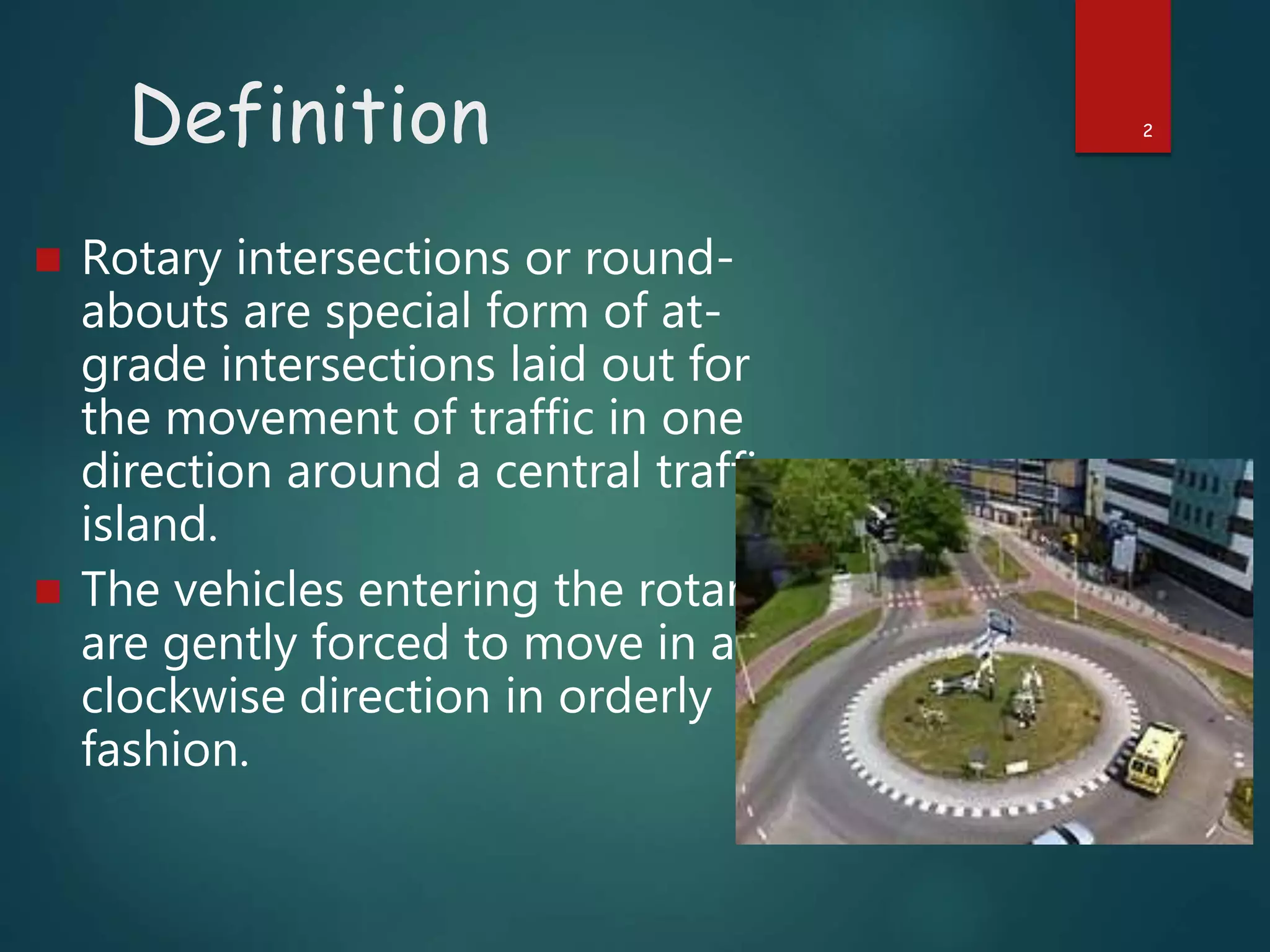
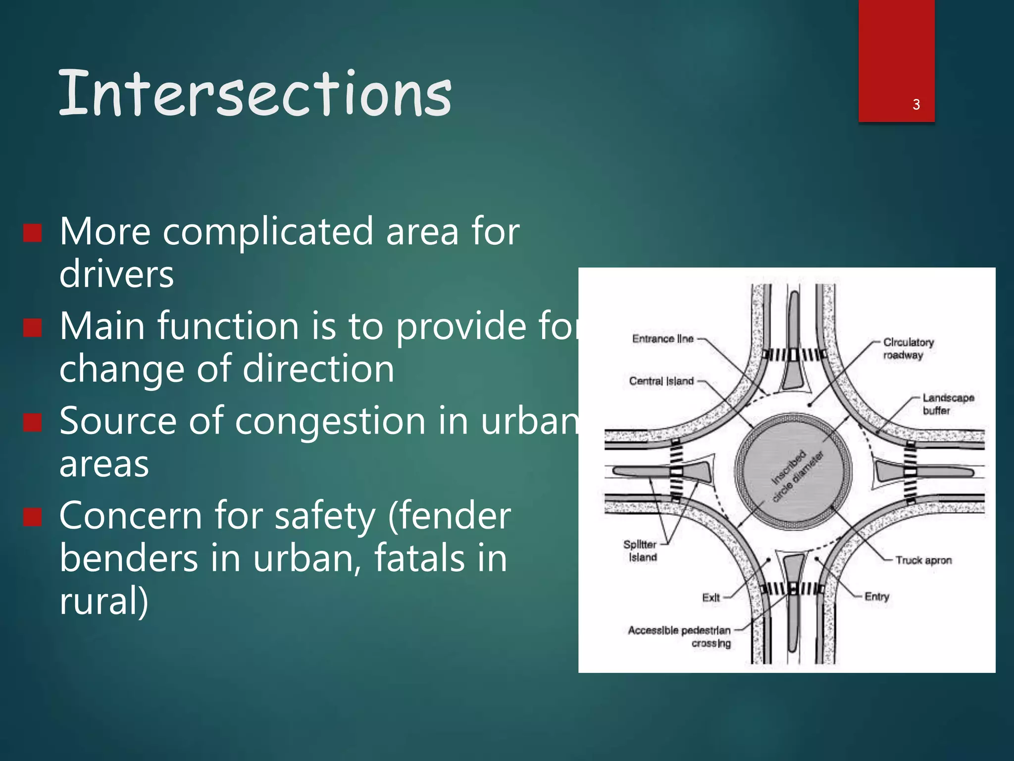
DESIGN OF
ROTARY
PREPARED BY –
SUVAM PATRA
SUBHAJIT KUNDU
SOUVIK MONDAL
SOMESH DE KARMAKAR
SAYAN ROY
SATYAKI SEN
DEPARTMENT OF CIVIL ENGINEERING (3RD YEAR)
1
Definition 2
 Rotary intersections or round-
abouts are special form of at-
grade intersections laid out for
the movement of traffic in one
direction around a central traffic
island.
 The vehicles entering the rotary
are gently forced to move in a
clockwise direction in orderly
fashion.
Intersections 3
 More complicated area for
drivers
 Main function is to provide for
change of direction
 Source of congestion in urban
areas
 Concern for safety (fender
benders in urban, fatals in
rural)
Types of Intersections
 Grade separated with ramps (freeway
interchange)
 Grade separated without ramps (over or
underpass with no access)
 At-grade
 Conventional
 Roundabouts
 New concepts (e.g., “continuous flow”)
4
Design Objectives
 “To reduce the severity of potential conflicts
between motor vehicles, pedestrians, and
facilities while facilitating the convenience, ease,
and comfort of people traversing the
intersection.” AASHTO
 Provide ease/control of access consistent with
the function of intersecting roadways
5
Width of Rotary 6
 IRC suggest that a two-lane of 7m width should be kept as
7m for urban roads and 6.5 for rural roads.
 Further for a three-lane road ofb10.5m is to be reduced to
7m and 7.5m respectively for urban and rural roads.
 The width of weaving section should be higher than the
width at entry and exit. The weaving with is given as,
W weaving= {(e1+e2)/2} +3.5 m
where,e1 = width of carriageway at the entry
e2 = width of carriageway at the exit
Capacity 7
 Transportation road research lab (TRL) proposed the
following empirical formula to find the capacity of the
weaving section
𝑸𝒘 =
280𝑤 1 +
𝑒
𝑤
[1 −
𝑝
3
]
[1 +
𝑤
𝑙
]
where is the average entry and exit width, is the weaving
width, is the length of weaving, and is the proportion of
weaving traffic to the non-weaving traffic.
 Four types of movements at a weaving section, and are the
non-weaving traffic and are the weaving traffic.
p =
𝒃+𝒄
𝒂+𝒃+𝒄+𝒅
Design consideration 8
 Length of Intersecting straights with minimum site dist
ances recommended by I.R.C. are: 50 km/h.
 Minimum Sight distance 15 m along minor roads
 Weaving Distance = 110 m, 145 m, 180 m and 220 m f
or speeds 50 km/h., 65 km/h., 80 km/h, 100 km/h. resp
ectively. Minimum Weaving length: 30 to 50 m
 All traffic islands are constructed 200 mm higher than
road level. They are provided with lawn, statue or foun
tains, painted with colours in contrast with the road pa
vement.
{1-(a/b)2} R4-{b2-5a2/4} R2 –(a2b2/2) = 0
Operational Requirements
 Provide adequate sight distance – for approac
h and departure maneuvers
 Minimize turning and through conflicts
 Provide natural paths for permitted movemen
ts
 Avoid geometry (sharp curves/steep grades)
that complicates the driving task and adverse
ly impacts acceleration or deceleration
9
Intersection Sight Distan
ce – ISD
 Allow drivers to have an unobstructed view of i
ntersection
 Required ISD is the length of cross road that
must be visible such that the driver of a turnin
g/crossing vehicle can decide to and complete t
he maneuver without conflict with vehicles appr
oaching the intersection on the cross road.
10
Adequate ISD
 Sight Triangle – area free of obstructions nece
ssary to complete maneuver and avoid collision
– needed for approach and departure (from sto
p sign for example)
 Allows driver to anticipate and avoid collisions
 Allows drivers of stopped vehicles enough view
of the intersection to decide when to enter
11
Sight Triangle
 Area free of obstructions necessary to comp
lete maneuver and avoid collision – needed fo
r approach and departure (from stop sign for
example)
 Consider horizontal as well as vertical, objec
t below driver eye height may not be an obst
ruction
 AASHTO assumes 3.5’ above roadway
12
13
14
Sight Distance Obstructions
Hidden Vehicle
ISD Cases
 No control: vehicles adjust speed
 Stop control: where traffic on minor roadwa
y must stop prior to entering major roadway
 Yield control: vehicles on minor roadway mu
st yield to major roadway traffic
 Signal control: where vehicles on all approac
hes are required to stop by either a stop sign
or traffic signal
 All way stop
 Stopped major roadway left-turn vehicles –
must yield to oncoming traffic
15
16
Large Tree
47’
72’
Example
50 mph
25 mph
Is sufficient stopping sight dis
tance provided?
17
Large T
ree
a = 47’
b = 72’
Example
50 mph
25 mph
25 mph > 15 mph, stopping sight
distance is not sufficient for
25 mph
db
da
bd
d
ad
a
a
b


da = 220 feet
db = 47’ (220’) = 69.9’
220’ – 72’
Sighting Rod and Target Rod
(AASHTO)
 For vertical sight
distance with vertical
curves
 Sighting rod- 3.5 feet tall
 Target rod- 4.25 feet tall
(Top portion and bottom
2 feet are painted
orange)
18
Sighting
Rod
Target
Rod
Measuring at an Uncontrolle
d Intersection 19
Observer
Assistant
Decision
Point
Obstruction
X
Y
20
Observer
Assistant
Movement of Assistant
Measuring at a Stop-controlled
Intersection
21
Observer
Assistant
Stop Bar
10 ft
SightLine
22
Assistant with Target Rod (4.25 ft)
Observer with Sighting Rod (3.5 ft)
THANK YOU
23

Design of rotary

  • 1.
    DESIGN OF ROTARY PREPARED BY– SUVAM PATRA SUBHAJIT KUNDU SOUVIK MONDAL SOMESH DE KARMAKAR SAYAN ROY SATYAKI SEN DEPARTMENT OF CIVIL ENGINEERING (3RD YEAR) 1
  • 2.
    Definition 2  Rotaryintersections or round- abouts are special form of at- grade intersections laid out for the movement of traffic in one direction around a central traffic island.  The vehicles entering the rotary are gently forced to move in a clockwise direction in orderly fashion.
  • 3.
    Intersections 3  Morecomplicated area for drivers  Main function is to provide for change of direction  Source of congestion in urban areas  Concern for safety (fender benders in urban, fatals in rural)
  • 4.
    Types of Intersections Grade separated with ramps (freeway interchange)  Grade separated without ramps (over or underpass with no access)  At-grade  Conventional  Roundabouts  New concepts (e.g., “continuous flow”) 4
  • 5.
    Design Objectives  “Toreduce the severity of potential conflicts between motor vehicles, pedestrians, and facilities while facilitating the convenience, ease, and comfort of people traversing the intersection.” AASHTO  Provide ease/control of access consistent with the function of intersecting roadways 5
  • 6.
    Width of Rotary6  IRC suggest that a two-lane of 7m width should be kept as 7m for urban roads and 6.5 for rural roads.  Further for a three-lane road ofb10.5m is to be reduced to 7m and 7.5m respectively for urban and rural roads.  The width of weaving section should be higher than the width at entry and exit. The weaving with is given as, W weaving= {(e1+e2)/2} +3.5 m where,e1 = width of carriageway at the entry e2 = width of carriageway at the exit
  • 7.
    Capacity 7  Transportationroad research lab (TRL) proposed the following empirical formula to find the capacity of the weaving section 𝑸𝒘 = 280𝑤 1 + 𝑒 𝑤 [1 − 𝑝 3 ] [1 + 𝑤 𝑙 ] where is the average entry and exit width, is the weaving width, is the length of weaving, and is the proportion of weaving traffic to the non-weaving traffic.  Four types of movements at a weaving section, and are the non-weaving traffic and are the weaving traffic. p = 𝒃+𝒄 𝒂+𝒃+𝒄+𝒅
  • 8.
    Design consideration 8 Length of Intersecting straights with minimum site dist ances recommended by I.R.C. are: 50 km/h.  Minimum Sight distance 15 m along minor roads  Weaving Distance = 110 m, 145 m, 180 m and 220 m f or speeds 50 km/h., 65 km/h., 80 km/h, 100 km/h. resp ectively. Minimum Weaving length: 30 to 50 m  All traffic islands are constructed 200 mm higher than road level. They are provided with lawn, statue or foun tains, painted with colours in contrast with the road pa vement. {1-(a/b)2} R4-{b2-5a2/4} R2 –(a2b2/2) = 0
  • 9.
    Operational Requirements  Provideadequate sight distance – for approac h and departure maneuvers  Minimize turning and through conflicts  Provide natural paths for permitted movemen ts  Avoid geometry (sharp curves/steep grades) that complicates the driving task and adverse ly impacts acceleration or deceleration 9
  • 10.
    Intersection Sight Distan ce– ISD  Allow drivers to have an unobstructed view of i ntersection  Required ISD is the length of cross road that must be visible such that the driver of a turnin g/crossing vehicle can decide to and complete t he maneuver without conflict with vehicles appr oaching the intersection on the cross road. 10
  • 11.
    Adequate ISD  SightTriangle – area free of obstructions nece ssary to complete maneuver and avoid collision – needed for approach and departure (from sto p sign for example)  Allows driver to anticipate and avoid collisions  Allows drivers of stopped vehicles enough view of the intersection to decide when to enter 11
  • 12.
    Sight Triangle  Areafree of obstructions necessary to comp lete maneuver and avoid collision – needed fo r approach and departure (from stop sign for example)  Consider horizontal as well as vertical, objec t below driver eye height may not be an obst ruction  AASHTO assumes 3.5’ above roadway 12
  • 13.
  • 14.
  • 15.
    ISD Cases  Nocontrol: vehicles adjust speed  Stop control: where traffic on minor roadwa y must stop prior to entering major roadway  Yield control: vehicles on minor roadway mu st yield to major roadway traffic  Signal control: where vehicles on all approac hes are required to stop by either a stop sign or traffic signal  All way stop  Stopped major roadway left-turn vehicles – must yield to oncoming traffic 15
  • 16.
    16 Large Tree 47’ 72’ Example 50 mph 25mph Is sufficient stopping sight dis tance provided?
  • 17.
    17 Large T ree a =47’ b = 72’ Example 50 mph 25 mph 25 mph > 15 mph, stopping sight distance is not sufficient for 25 mph db da bd d ad a a b   da = 220 feet db = 47’ (220’) = 69.9’ 220’ – 72’
  • 18.
    Sighting Rod andTarget Rod (AASHTO)  For vertical sight distance with vertical curves  Sighting rod- 3.5 feet tall  Target rod- 4.25 feet tall (Top portion and bottom 2 feet are painted orange) 18 Sighting Rod Target Rod
  • 19.
    Measuring at anUncontrolle d Intersection 19 Observer Assistant Decision Point Obstruction X Y
  • 20.
  • 21.
    Measuring at aStop-controlled Intersection 21 Observer Assistant Stop Bar 10 ft SightLine
  • 22.
    22 Assistant with TargetRod (4.25 ft) Observer with Sighting Rod (3.5 ft)
  • 23.

Editor's Notes

  • #19 All heights and sight distances come directly from the Big Green Book or the Little Green Book
  • #20 Observer with the sighting rod (3.5 ft) positions himself at the appropriate distance from the intersection. Assistant with the target rod (4.25 ft) moves away from the intersection until intersection until the target rod disappears. When it does the assistant stops and measures from that point back to the intersection.
  • #22 Observer with the sighting rod (3.5 ft) positions himself 10 ft back from the stop bar. Assistant with the sighting rod (4.25 ft) moves away from the observer until the target rod is no longer visible. When it is not, the observer stops and measures back to the intersection.