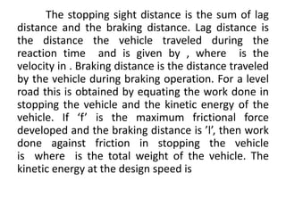
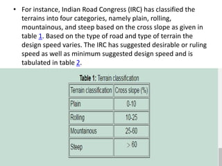
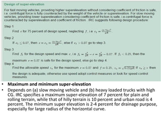
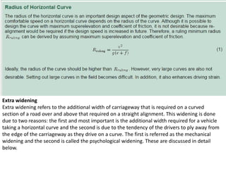
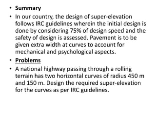
The document discusses highway geometric design and its key elements. It covers the importance of geometric design in providing efficient and safe traffic operations. The main elements of geometric design discussed include cross section elements like pavement width and slope, sight distances at curves and intersections to allow safe vehicle movement, horizontal and vertical alignment details, and intersection design. Design is governed by factors like design speed, topography, traffic, and costs. Sight distance, which ensures visibility of the road ahead, is an important consideration, with discussions of stopping sight distance and other sight distance types.
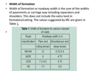
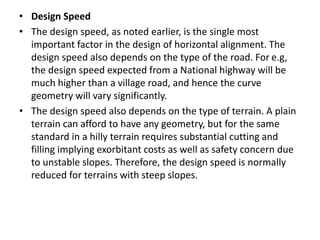
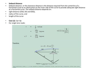
![Summit curve
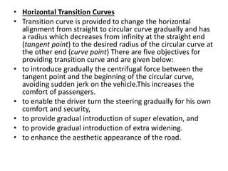
Summit curves are vertical curves with gradient upwards. They are formed when two gradients
meet as illustrated in figure 1 in any of the following four ways:
when a positive gradient meets another positive gradient [figure 1a].
when positive gradient meets a flat gradient [figure 1b]. .
when an ascending gradient meets a descending gradient [figure 1c]. .
when a descending gradient meets another descending gradient [figure 1d].](https://image.slidesharecdn.com/module2bmj-240127070537-85e34c5c/85/Transportation-engineering-module-2-ppt-58-320.jpg)