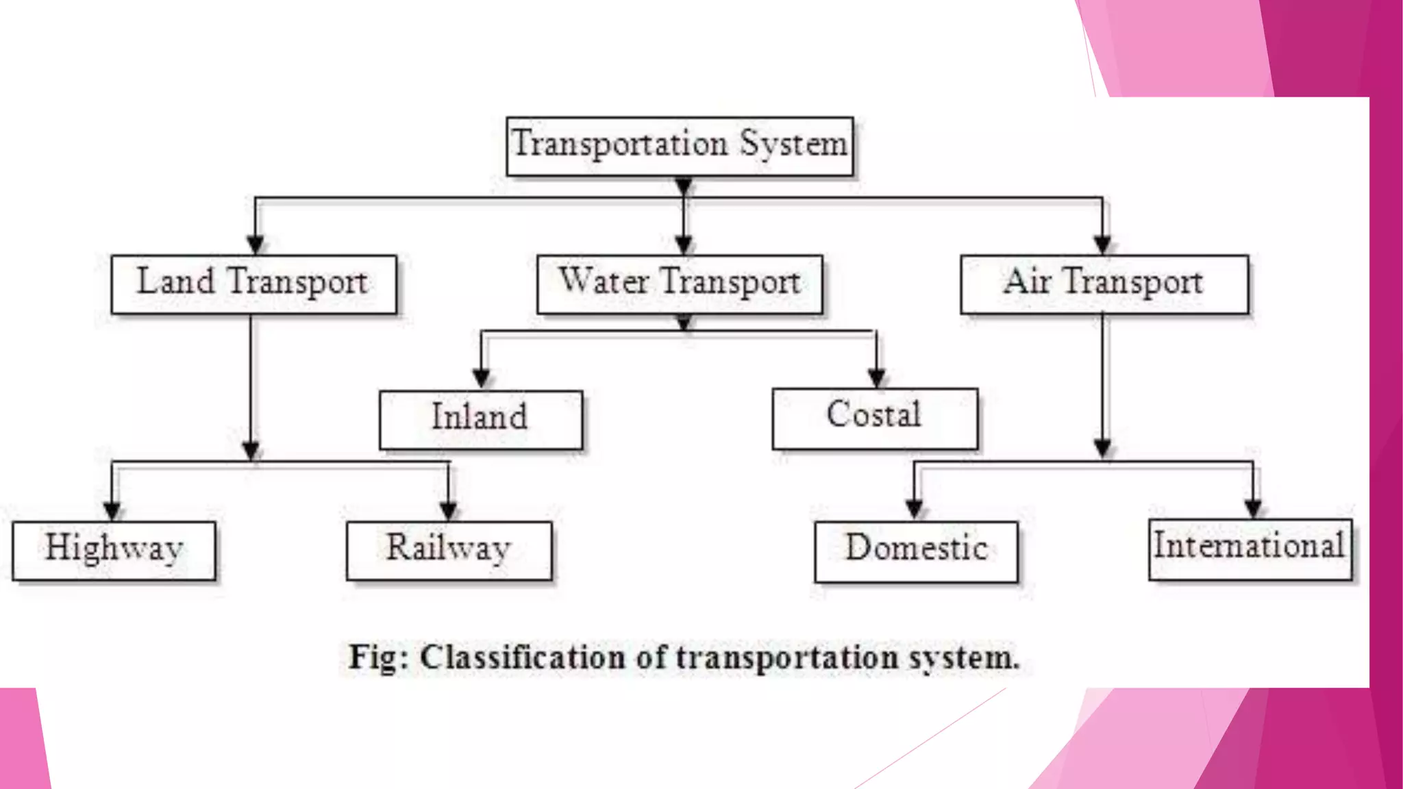
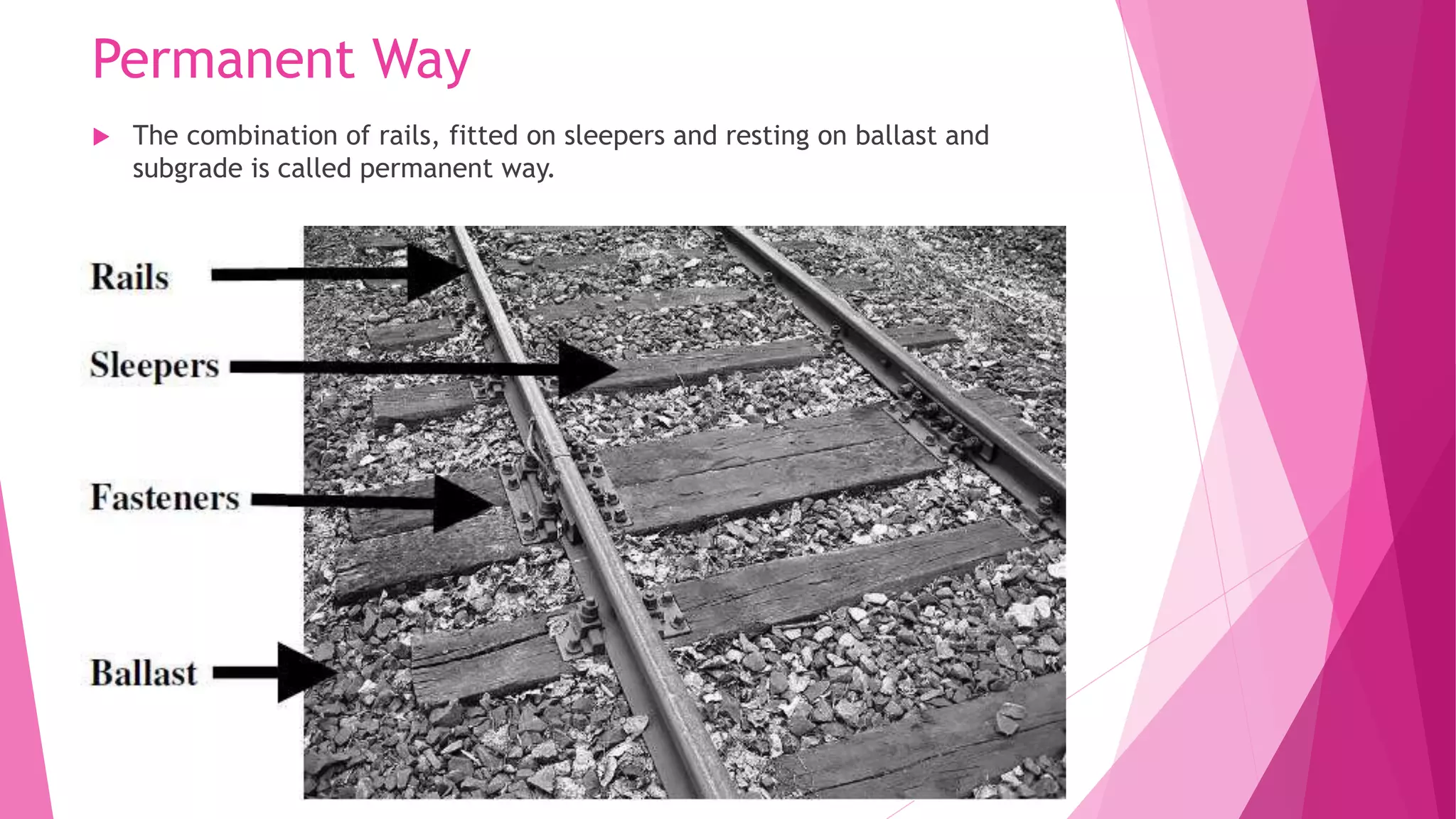
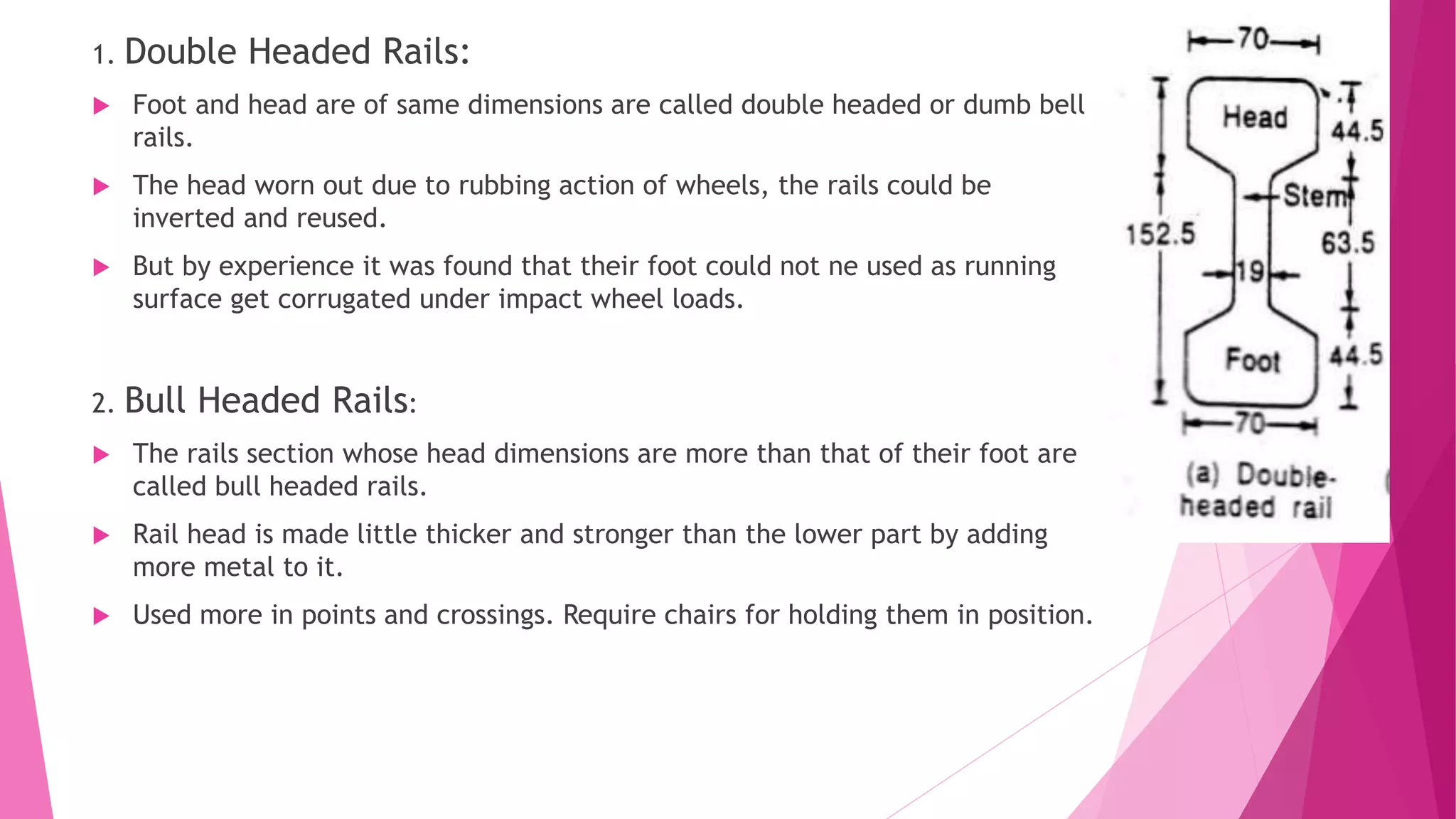
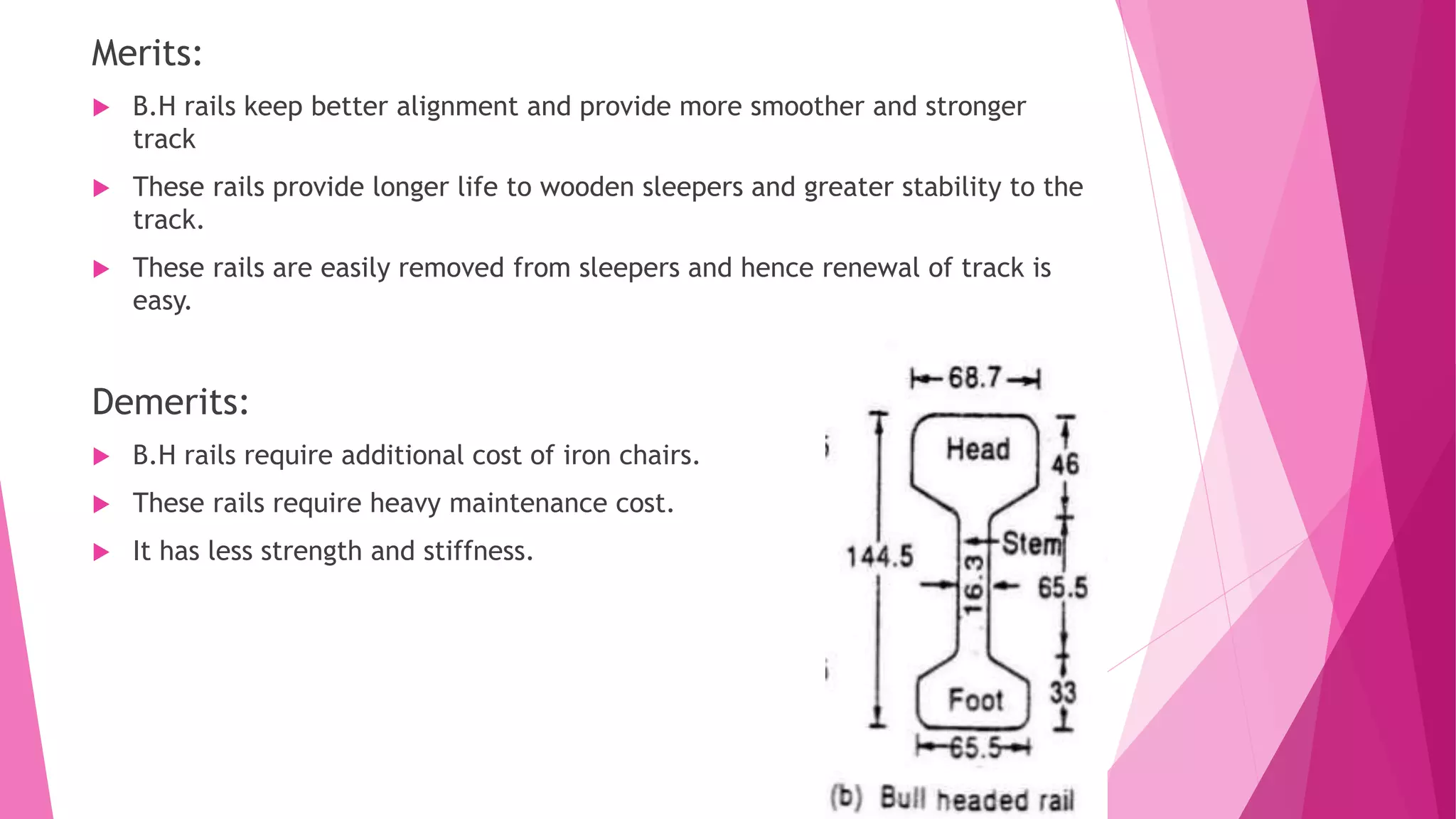
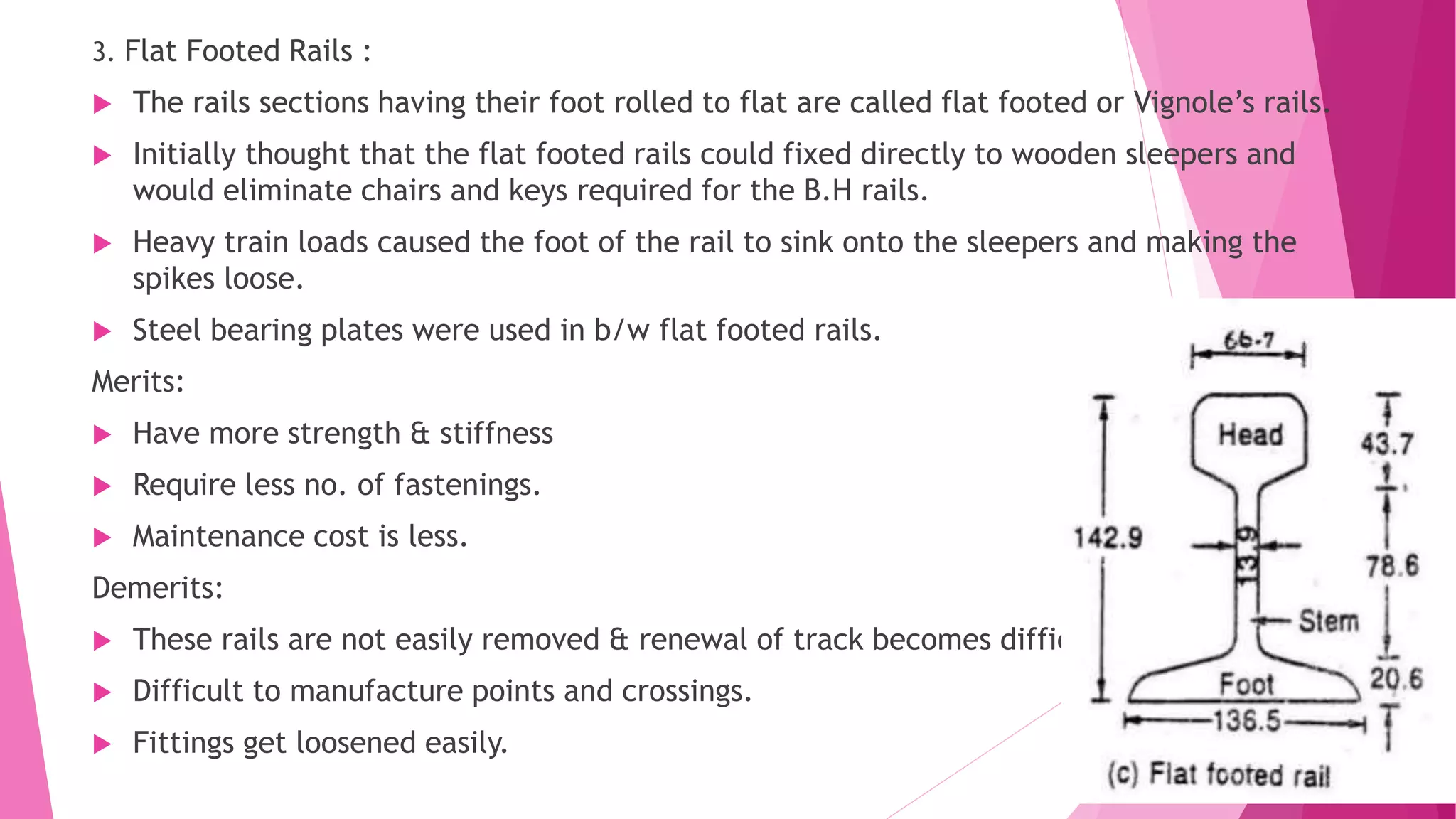
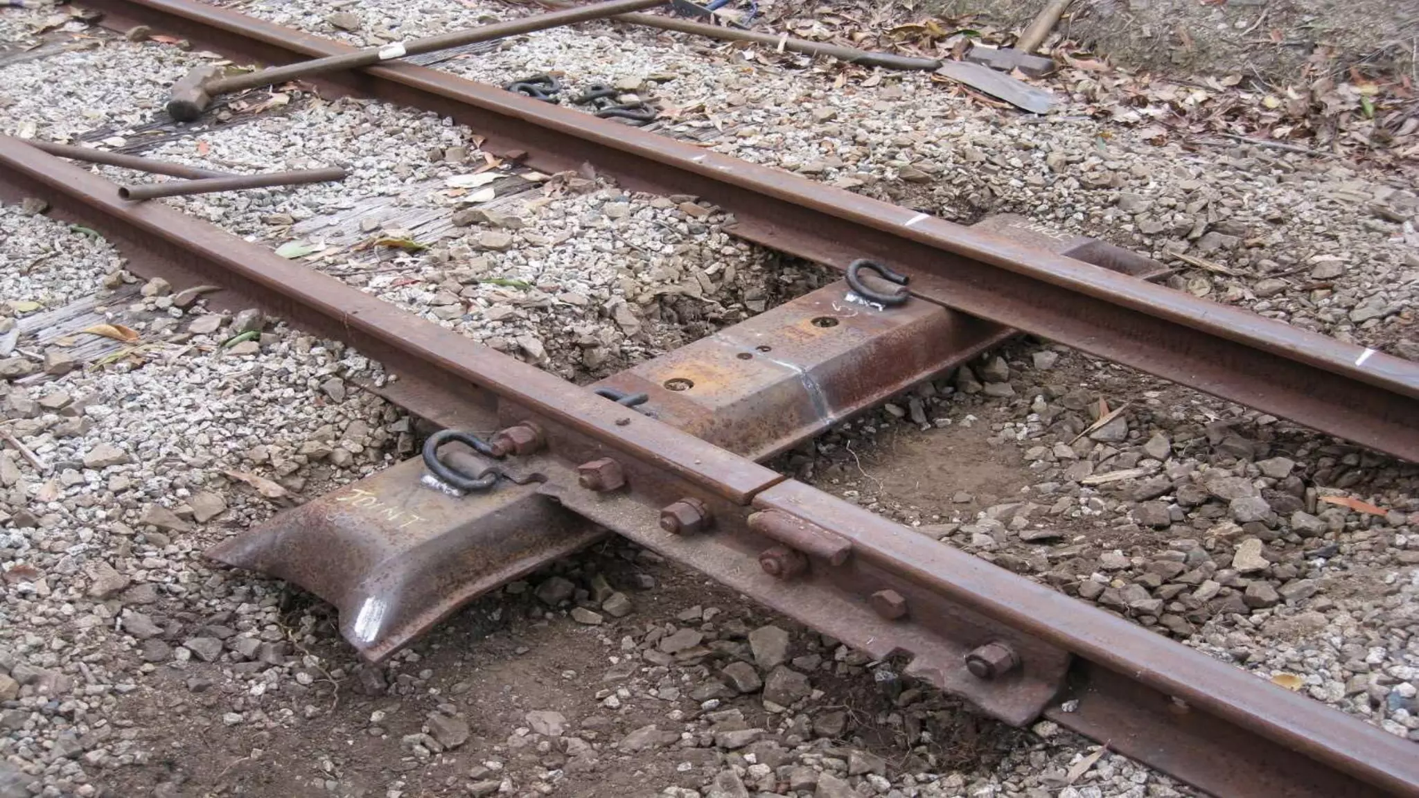
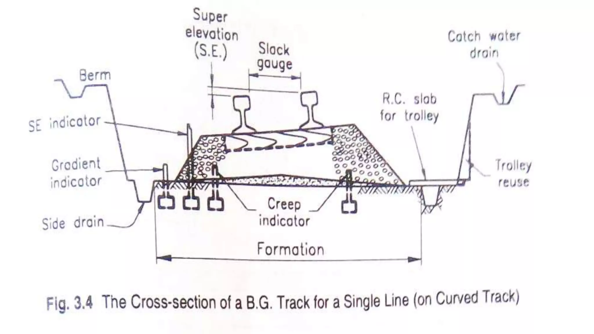
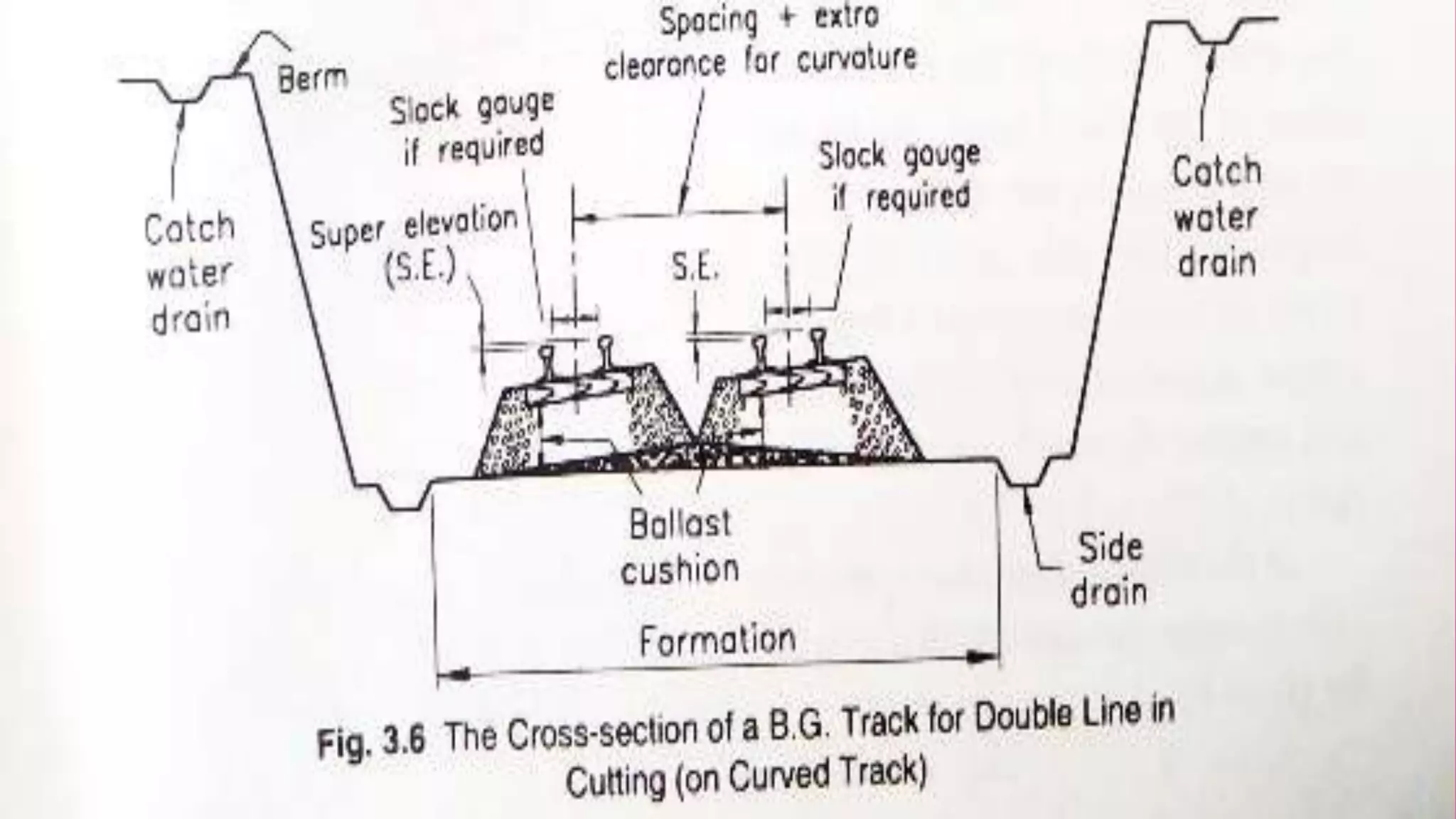
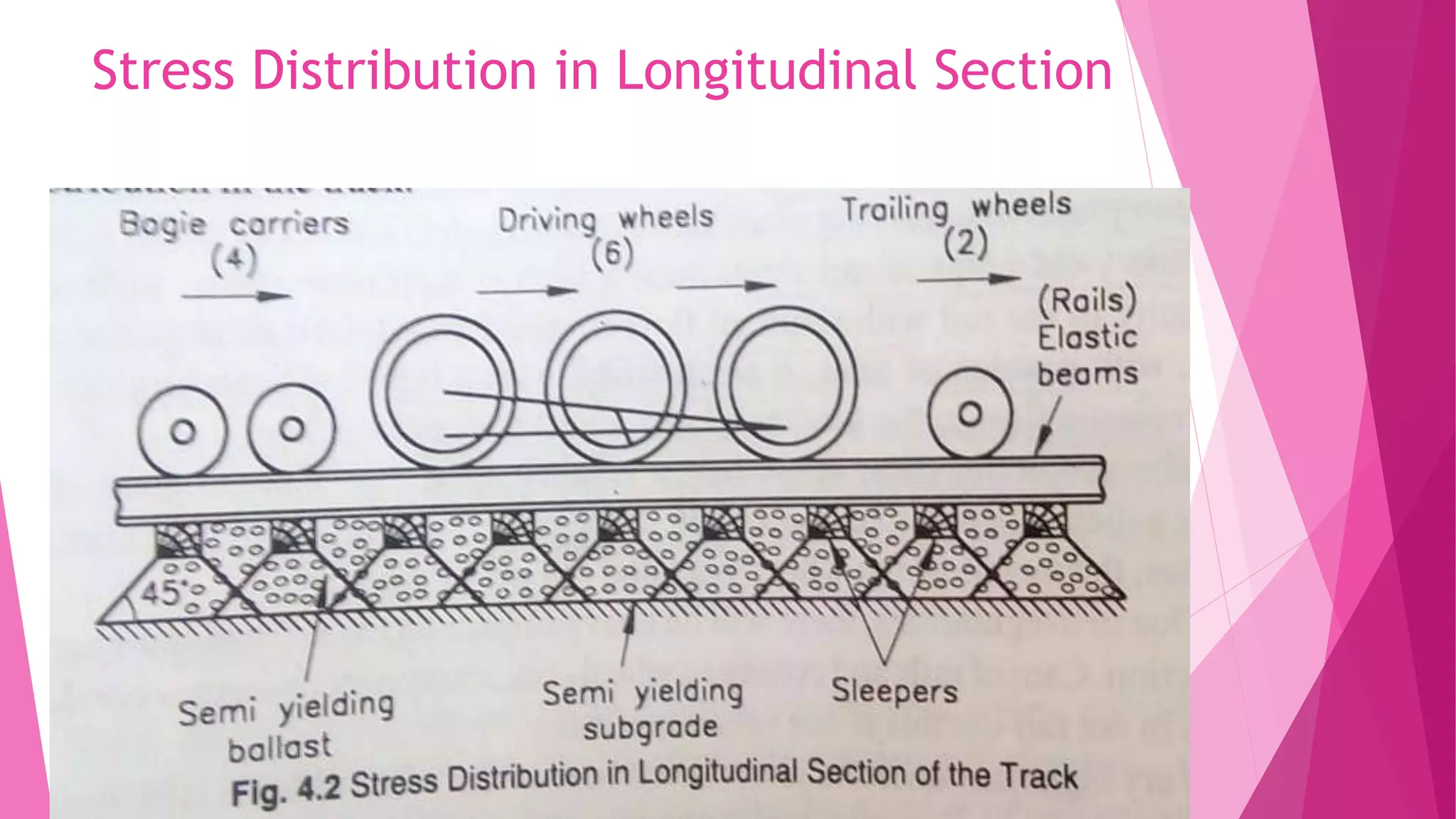
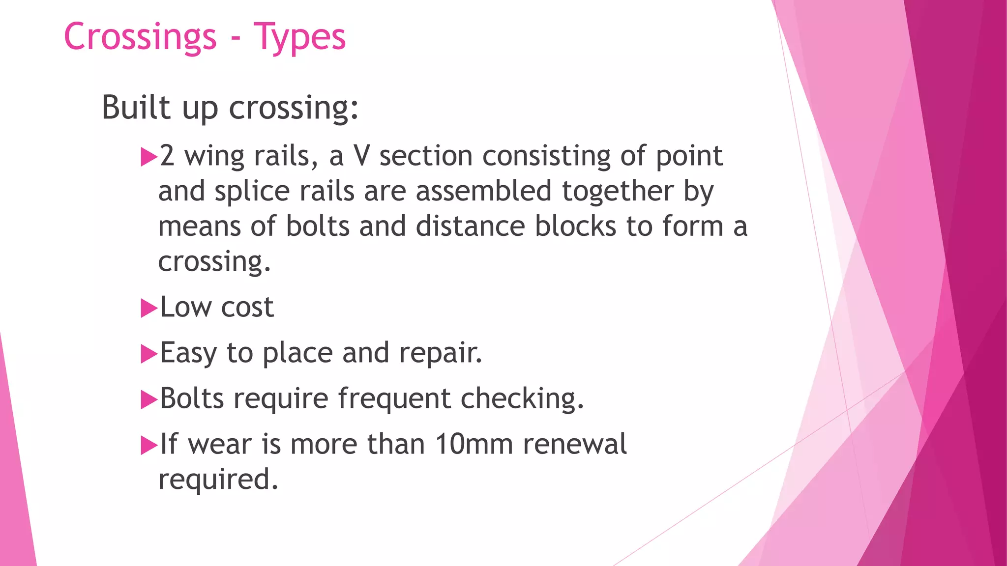
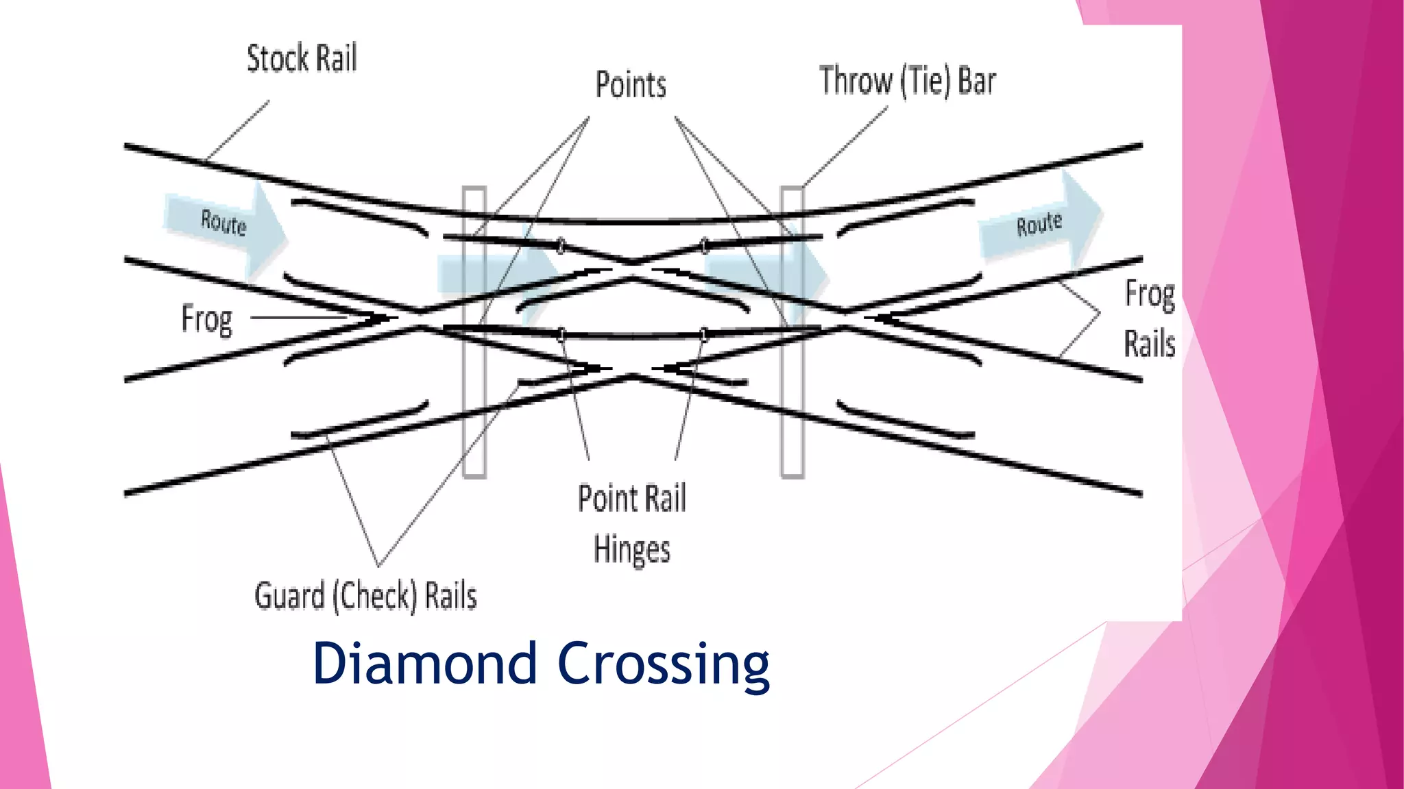
SlideShare a Scribd company logo
UNIT 1 – RAILWAY
PLANNING
Introduction
 Transportation is regarded as an index of
economic, social and commercial progress of a
country.
 An adequate transportation is indispensable for
economic and social progress of nation and the
world as a whole.
 Land, water and air have been used by mankind
for developing the transport modes like Railways,
Highways, Waterways.
Classification of Transportation
 Land Transport ex: Highway, Railway, cable
way, ropeways etc.
 Water Transport ex: canal ways, river ways,
ocean ways, lake ways etc.
 Air Transport ex: Airways.
Terminology
 Ballast: it is the granular material packed under and
around the sleeps to transfer loads from sleepers to
ballast. It helps in providing elasticity to the track.
 Broad Gauge: the gauge of a track in which the distance
between the running faces of two track rails is 1.676m is
termed as B.G
 Coning of Rails: the wheels are coned at a slope of 1 in 20
to prevent from rubbing the inside face of the rail head
and to prevent lateral movement of the axle with its
wheels.
 Creep: it is the longitudinal movement of rails in a track.
Gauges in Railway Track
 Def: The ‘Gauge’ of a railway track is defined as the clear distance b/w inner
or running faces of two track rails.
 The distance b/w the inner faces of a pair of wheels is called wheel gauge.
Type of gauge Gauge width
Standard gauge (B.G) 1.67 m
Meter gauge (M.G) 1.0m
Narrow gauge (N.G) 0.762m
Feeder track gauge (L.G) 0.610m
Permanent Way
 The combination of rails, fitted on sleepers and resting on ballast and
subgrade is called permanent way.
 In permanent way, the rails are joined in series by fish
plates and bolts & then they are fixed to sleepers by
different types of fastenings.
 On curved tracks, super elevation is maintained by ballast
and the formation is levelled.
 Addl. Quantity of ballast is provided on the outer cess of
each track for which the base width of the ballast is kept
more than for a straight track.
Requirements of an Ideal Permanent way
 Permanent track is regarded to be semi elastic in nature.
 The gauge should be correct and uniform
 The rails should be in proper level. Two rails must be at
same level.
 The alignment should be correct. (i,e) it shd be free from
irregularities.
 The gradient should be resilient and elastic in order to
absorb shocks and vibrations of running track.
 The radii and super elevation on curves should be properly
designed and maintained.
 Drainage system must be perfect for enhancing safety and
durability of track.
 Joints, including points and crossings which are regarded to
be weakest points of the railway track, should be properly
designed and maintained.
 If there is trouble from the creep, the preventionary
measures should be to prevent it.
 There should be adequate provision for easy renewals and
replacements.
 The track structure should be strong, low in initial cost as
well as maintenance cost.
Capacity of a Railway Track
 It is the hourly capacity of the track to handle the
trains safely or it is the number of trains that can
be run safely on a track per hour.
Rails
 The rails on the track can be considered as steel girders
for the purpose of carrying axle loads.
 They are made in high carbon steel to withstand wear and
tear.
 Flat footed rails are mostly used in railways
Functions:
 It provide hard, smooth & unchanging surface for heavy
loads with min friction b/w rails and wheels.
 Rails bear stresses, lateral, thermal & braking forces.
Types of Rails
 Double headed rails
 Bull headed rails
 Flat footed rails
1. Double Headed Rails:
 Foot and head are of same dimensions are called double headed or dumb bell
rails.
 The head worn out due to rubbing action of wheels, the rails could be
inverted and reused.
 But by experience it was found that their foot could not ne used as running
surface get corrugated under impact wheel loads.
2. Bull Headed Rails:
 The rails section whose head dimensions are more than that of their foot are
called bull headed rails.
 Rail head is made little thicker and stronger than the lower part by adding
more metal to it.
 Used more in points and crossings. Require chairs for holding them in position.
Merits:
 B.H rails keep better alignment and provide more smoother and stronger
track
 These rails provide longer life to wooden sleepers and greater stability to the
track.
 These rails are easily removed from sleepers and hence renewal of track is
easy.
Demerits:
 B.H rails require additional cost of iron chairs.
 These rails require heavy maintenance cost.
 It has less strength and stiffness.
3. Flat Footed Rails :
 The rails sections having their foot rolled to flat are called flat footed or Vignole’s rails.
 Initially thought that the flat footed rails could fixed directly to wooden sleepers and
would eliminate chairs and keys required for the B.H rails.
 Heavy train loads caused the foot of the rail to sink onto the sleepers and making the
spikes loose.
 Steel bearing plates were used in b/w flat footed rails.
Merits:
 Have more strength & stiffness
 Require less no. of fastenings.
 Maintenance cost is less.
Demerits:
 These rails are not easily removed & renewal of track becomes difficult.
 Difficult to manufacture points and crossings.
 Fittings get loosened easily.
Length of Rails
 The rails of larger length are preferred to smaller length
of rails, because they give more strength & economy.
 IR adopt standard rail length of 12.80m (42ft) for B.G and
11.89m (39ft) for M.G.
 Joints are the weakest points in railway tracks.
Sleepers
 These are the members generally laid transverse to the rails on
which rails are supported & fixed, to transfer the loads from rails
to the ballast & subgrade below.
Functions:
 To hold the rails to correct gauge.
 To hold the rails in proper level
 To act an elastic medium in b/w ballast & rails to absorb the
blows & vibrations of moving loads.
 It also add to longitudinal and lateral stability of the permanent
track on the whole.
Requirements of Good Sleepers
 The sleepers shd be strong to act as a beam under
loads.
 It shd be economical.
 Maintain correct gauge.
 Shd provide sufficient bearing area for the rail.
 Sleepers shd have sufficient weight for stability
 It should facilitate easy fixing and taking out of rails
without disturbing them.
 They posses easy removal and replacement of ballast.
 Able to resist impact and vibrations of moving trains.
Types of sleepers
According to materials:
 Wooden sleepers
 Metal sleepers  cast iron sleepers, steel sleepers.
 RCC sleepers
 Pre-stressed concrete sleepers.
Wooden Sleepers
 Satisfy all the requirements and suitable for track circuiting.
 Life of wooden sleepers depends on their ability to resist wear, attack by
white ants and quality of timber used.
 Sal, teak, deodar & chair wood.
 B.G  2740 x 250 x 130 mm
 M.G  1830 x 203 x 114 mm
 N.G  1520 x 150 x 100 mm
Steel Sleepers
 Steel made of 6mm thick sheets. At the time of pressing
of sleepers, an inward slope of 1 in 20 on either side is
provided to achieve tilt of rails.
 Standard size is 2680 mm
Types:
 Key type steel sleepers
 Clip and bolt type steel sleepers
Cast Iron Sleepers
 These are made of cast iron.
Types:
1. Pot or bowl sleepers
2. Plate sleepers
3. Box sleepers
4. CST-9 sleepers
5. Duplex sleepers
Advantages:
 Life is more.
 Maintenance cost is low
 Durable
Disadvantages:
 More ballast is required than any other type
 no. of fittings required is more
 Liable to break
 Not suitable for all type of ballast
RCC Sleepers
Merits:
 Have long life - 40 to 60 years
 Free from natural decay & attack of insects
 Require less fittings
 Provide more lateral and longitudinal rigidity as compared
to others
 Maintenance cost is low.
Sleeper Density
 The space b/w two adjacent sleepers determine the
effective span of the rail over the sleepers.
 The spacing of sleepers in a track depends on the axle
load which the track is expected to carry lateral thrust of
locomotives to which it is subjected.
 It’s the no. of sleepers per rail length and it is specified as
(M + x or N + x), where M  length of rail in m, x is a
number, varying acc to foll factors fixed by Railway board
for various axle loads.
 Methods of providing rail joints
 Speed of trains
 Max axle load expected on track.
Ballast
 It is the granular material usually broken stone or brick,
shingle or kankar, gravel or sand placed & packed below &
around the sleepers to transmit the load from sleepers to
formation and also for drainage.
Details of Ballast Sections:
Dimensions BG MG NG
Width of ballast 3.35m 2.25m 1.83m
Depth of ballast 20 to 25cm 15 to 20cm 15cm
Quantity of stone
ballast/m length
1.036m3 0.71m3 0.53m3
Functions
 To hold the sleepers in position and preventing the lateral
& longitudinal movement.
 To distribute the axle load uniform from sleepers to a
large area of formation.
 To provide elasticity to the track. Acts as elastic mat b/w
subgrade and sleepers.
 To drain water from the track
 To prevent growth of weeds inside the track.
 To provide easy maintenance.
Characteristics of Good Ballast
 It should have sufficient strength to resist
crushing under heavy loads of moving trains.
 It should be durable enough to resist abrasion and
weathering action.
 Shd have rough and angular surface to provide
good lateral and longitudinal stability to the
sleepers.
 Shd have good workability, have easy spread of
formation.
 Shd be cheaply available.
 Shd not have any chemical action on metal
sleepers and rails.
Types
 Broken stone
 Gravel
 Sand
 Ashes or cinders
 Kankar
 Moorum
 Blast furnace slag
 Brick ballast
Rail Fixtures & Fastenings
 Track Fittings & rail fastenings are used to keep the rails in the proper
position and to set the points & crossings properly.
 They link the rails endwise and fix the rails either on chairs fixed to sleepers.
 The important fittings commonly use din a permanent way are the foll,
 Fish plates
 Spikes
 Bolts
 Chairs
 Blocks
 keys
 Fish plates: are used in rail joints to maintain the continuity of the rails & to
allow for any expansion or contraction of the rail caused by temperature
variations.
Spikes
 For holding the rails to the wooden sleepers
spikes of various types are used.
 Dog spikes
 Screw spikes
 Round spikes
 Standard Spikes
Coning of Wheels
 The flanges are never made flat. But, they are in the shape
of a cone with a slope of about 1 in 20.
 As the wheels are set on the axle, there is some chance for
lateral movement b/w the flanges of the wheels and the
rails.
 Without coning, the flanges would cause, a slight but sudden
stock to the sides of the rails.
 It is done mainly to maintain the vehicle in the central
position wrto the track.
Creep in Rails
 Def: it is defined as the longitudinal movement of
rails wrto to sleepers in a track.
 Indication of creep:
 Closing of successive expansion spaces at rail
joints in the direction of creep and opening out of
joints at the point from where the creep starts.
 Marks on flanges and webs of rails made by spike
heads by scraping or scratching as the rails slide.
Effects of creep
 Difficulty in refining of rail.
 Operation of switches
 Points and crossing gets pulled/pushed.
 Rail joints gets opened.
 Surface and alignment of track gets disturb.
Defects in Rails
Wear on Rails:
 Wear is one of the prominent defects of rails.
When the axle loads are abnormally heavy and
the train moves with very fast speed then the
concentrated stresses exceed the elastic limit
resulting in metal flow.
 On the gap or joint the ends are battered and at
the curves the occurrence of skidding, slipping
and the striking of wheel flanges with rails results
in wear and tear of rails.
Classification of Wear
A) Based on location:
 On sharp curves
 On gradients
 On approaches to stations  brakes are frequently applied.
 In tunnels
 Where sand is used on rails to produce more friction on damp rails but on the
contrary it gives more wear.
 The gases emitting from the engine being confined attack the metal and
result in wear.
 In coastal area, due to action of sea breeze, the corrosion of metal
takes place.
 On weak foundations  sinking of rails due to heavy loads gives
uneven surface which results in wear.
B) basis of position of wear:
 Wear on top or head of rail.
 Wear at the ends of rails
 Wear on the sides of the head.
Route Alignment Survey
 Alignment may be defined as the layout of the centre line
of a railway track.
 Basic requirement of an ideal alignment are economic,
easy for construction, operation and maintenance, safe.
 Factors controlling alignments
 Obligatory points
 Traffic potential
 Geometric design standards
 Topography
 Economic viability
 Techno economic characteristics
 Other considerations
Obligatory points
 It is the controlling points which govern the alignment of railway
tracks. Alignment has to pass through are,
 Important towns and cities
 Shortest width and permanent path of rivers
 Hill passes
Engineering Survey for track alignment
 Traffic survey
 Reconnaissance survey
 Preliminary Survey
 Final Location & Detailed survey
Traffic Survey
 Detailed study of traffic conditions in the area to
determine,
A) most promising route for railway
B) Possible traffic the railway line will carry.
C) standard of railway line to be followed.
 The survey team should visit all trade centres in the area
and consult local bodies, state govt, citizens regarding
trade & industry.
Following info shd be collected in detail:
 Human Resources
 Agricultural & mineral resources
 Pattern of trade & commerce
 Industries located & projected
 Prospects of tourist traffic.
 Existing transport facilities
 Locations of important govt & private offices.
Reconnaissance Survey
 Survey consists of a rapid & rough investigations
of the area with a view to determine technical
feasibility of proposal & rough cost of a new line.
 It is based on controlled survey maps and other
data already available without any detailed
investigations in the field.
 General topography is studied by the survey team
and field data are collected.
Survey Instruments
 To measure approximate distance & heights:
Instruments Purpose
Prismatic compass To get magnetic bearing of proposed
alignment
Aneroid barometer To ensure relative heights of various
points
Abney level or Clinometer To measure the gradients or angles of
slopes
Binocular To view physical features
Pedometer To get an idea of total length
traversed while walking
Modern Surveying Instruments
 Using Infra Red beams, LASER beams, computers.
EDM  Electromagnetic Distance Measurement
 EDM rapidly & automatically measures both
horizontal & vertical distances.
 Readings are displayed on built in computer.
 Geodimeter & Tellurimeter – upto 80 km during
day or night.
Laser – Light Amplification by Stimulated
Emission of Radiation
 Low diversion – used for alignment purposes.
 Invisible line of sight in ordinary survey
instrument is replaced by bright red beam of the
laser.
 Distances up to 70 km can be measured.
 For short distances Infra Red beams are
measured.
Field Data – During Reconnaissance
1. General topography of the country
2. Approx height of different points falling on the
alignments
3. Position of rivers, streams and some hydrological
data
4. Positions of roads and highways.
5. Nature of soil
6. Rough location of various sites
7. Controlling points on alignment.
8. Facilities for construction.
Preliminary Survey
 Consists of a detailed instrumental examination of the
route, selected from reconnaissance survey in order to
estimate the cost of proposed line.
Instruments:
 Theodolite – traversing & pegging the centre line.
 Tacheometer – plotting the main features
 Dumpy level – taking longitudinal & c/s levels.
 Plane table – getting details of various features
 Prismatic compass – measuring magnetic bearing.
Data
1. Geological info – soil strata, sand, aggregates, brick,
cement & timber
2. Source of availability of construction materials
3. Availability of labour & drinking water
4. Full details of land & building acquired.
5. Details of existing bridges & culverts
6. Details of road crossings / level crossings.
7. H.F.L & low water level of all rivers, streams.
8. Full details of station sites.
Final Location Survey
 It is done to prepare working details & make accurate cost
estimated.
Difference b/w preliminary & detailed survey:
1. In final location, alignment is fully staked with the help of
a theodolite, where as it is not obligatory to do so in case
of prelims.
2. In final location, more detailed project report is prepared
and submitted.
3. All working dwgs are prepared in final location.
Tasks
1. Centre line os fully marked by pegs at 20m. At
each 100m, a large peg shd be used.
2. Masonry pillars are built at tangent points of
curves & along the centre line at intervals of
500m.
3. Longitudinal & c/s levelling is done.
4. Sites for station yards are fully demarcated.
Drawings
1. General map of the country traversed by project
at a scale of about 20km to 1 cm.
2. Index map, 2.5 km to 1 cm
3. Index plan & sections
4. Detailed plans & sections
5. Plans & c/s
6. Plans of station yards.
7. Detailed dwgs of structures.
8. Plans of junction arrangements.
Modern Surveying Techniques for
Different Terrain
1. Satellite imagery (remote sensing)
2. Aerial photographs
3. Topographic maps / contour maps
4. Digital terrain modelling (DTM)
5. Photogrammetric plotted sheets.
Engineering survey through modern
methods
 Planning needs precious and cost effective methods of
surveying. Innovative techniques like remote sensing and
advancement in hardware and software technology had led to
sophisticated and scientific methods.
 Remote sensing data products such as aerial photos and high
resolution satellite imageries, modern surveying
equipment/systems such as Electronic Distance Meter (EDM)
 Total Station
 Global positioning System (GPS)
 Geographical Information System (GIS)
GPS
 This instrument measures any point any where on the globe.
This system uses a set of satellites at a distance of about
10000 km above earth.
 All weather and day and night surveying is possible with the
instrument. It is capable if measuring distances even up to
thousands of kilometres.
EDM
 Works on the principle of time taken for electromagnetic
waves to travel between the given origin and destination.
 Typical EDM equipment can measure a distance up to 5 – 10
km with an accuracy of one to two cm.
Total Station
 Works on same principle as that of EDM. TS measures
distances and angles with very great accuracy.
 TS can provide angle measurement with a least
count of one second (1/3600th of a degree). They
also provide with software for automatic recording
and printing of measurements.
 TS can provide angle measurement simultaneous
provide horn and vertical angle measurement. This
reduces human intervention and elimination human
errors.
Geometric Design of Track
 Geometric design should be such as to provide maximum
efficiency in the traffic operation with maximum safety at
reasonable cost.
Gradient :
 It is the rate of rise or fall of the track. Expressed in V:H
Purpose of providing gradient:
 To provide uniform rate of rise or fall,
 To reduce cost of earth work,
 To reach different stations at different level.
Types of Gradient
1)Ruling gradient: The steepest gradient allowed on the track
section. It determines the max load that the locomotive can
haul that section. The steep gradient needs more powerful
locomotives, smaller train loads, lower speed, resulting in
costly hauling.
 –In plains: 1 in 150 to 1 in 200
 –In hilly regions: 1 in 100 to 1 in 150
2) Momentum Gradient: The gradient on a section which are
steeper than the ruling gradient acquire sufficient momentum
to negotiate them are known as momentum gradient.
3) Pusher gradient: A ruling gradient limits the maximum weight of
a train which can be hauled over the section by a locomotive. If the
ruling gradient is so severe on a section that, it needs the help of
extra engine to pull the same load then this gradient is known as
pusher or helper gradient.
 In Darjeeling Railways 1 in 37 pusher gradient is used on Western
Ghats BG Track.
4) Gradient at stations: At stations gradient are provided sufficient
low due to following reason:
 –To prevent movement of standing vehicle
 –To prevent additional resistance due to grade.
 On Indian railways, maximum gradient permitted is 1 in 400 in
station yards & min is 1 in 1000 for easy drainage of rain water.
Grade Compensation on Curves
 It is the reduction in gradient on curved portion of a track.
 On curved track, extra pull is required to pull the train due to
more tractive resistance.
 Some compensation should be given in ruling gradients to
overcome the increased tractive resistance to a certain limit
and to pull the trains with same speed.
 BG track: 0.04% per degree of curve
 MG track: 0.03 % per degree of curve
 NG track: 0.02 % per degree of curve
Degree of curve
 A curve is defined by its degree or radius. The degree
of a curve is the angle subtended at the center by a
chord of 100 feet or 30.48m.
 If R is the radius of curve,
•Circumference of the curve= 2 ∏ R
•Angle subtended at the center by the circle = 360
degree
•Angle subtended by the arc of 30.48m = 1750/R
Thus, a 1 degree curve has a radius of 1750 m.
D = 1750 / R, D= degree, R = radius.
 Maximum degree of curvature for B.G = 10 deg
(min. R = 175m)
 Maximum degree of curvature for M.G = 16 deg
(min. R = 109m)
 Maximum degree of curvature for N.G = 40 deg
(min. R = 44m)
 V = 4.4 √(R – 70)  B.G
 V = 4.35 √(R – 67)  M.G
 V = 3.6 √(R – 6.1)  N.G , V in kmph.
Super elevation on Curves (Cant)
 Cant is defined as the difference in height between the
inner and outer rails on the curve. It is provided by
gradually raising the outer rail above the inner rail
level. The inner rail is considered as the reference rail
and normally is maintained at its original level. The
inner rail is known as the gradient rail.
Function of super elevation:
 Neutralizes the effect of lateral force.
 It provides better load distribution on the two rails.
 It reduces wear and tear of rails and rolling stock.
 It provides smooth running of trains and comforts to
the passengers.
Speeds
 Equilibrium speed: It is the speed at which the effect of centrifugal
force is exactly balanced by the super elevation provided. It can also
be said that when the speed of a vehicle running on a curved track is
such that the resultant weight of the vehicle and the effect of radial
acceleration is perpendicular to the plane of rails and the vehicle is
not subjected to an unbalanced radial acceleration, is in equilibrium
then its particular speed is called equilibrium speed.
 Maximum permissible speed: This is the highest speed which may be
allowed or permitted on a curved track taking into consideration of
the radius of curvature, actual cant, cant deficiency, cant excess and
the length of the transition curve. When, the maximum permissible
speed on the curve is less than the maximum sanctioned speed of the
section of a line, permanent speed restriction become necessary on
such curves.
Cant deficiency
 Cant deficiency is the difference between the
equilibrium cant (theoretical) necessary for the
maximum permissible speed on a curve and the
actual cant provided there. As per Indian
Railways, Cant deficiency is recommended as
follow:
 BG Track: 75 mm
 MG track: 50 mm
 NG track: 40 mm
Negative Super Elevation
 When a main line is on a curve &
has a turn out leading to a branch
line, the super elevation
necessary for the average speed
of trains over the main line
cannot be provided.
Cant Excess
 When a train travels on a curved track at a speed
lower than the equilibrium speed, then the cant
excess occurs. It is the difference between the
actual cant provided and the theoretical cant
required for such lower speeds. Maximum value
for cant excess is
 BG track: 75 mm
 MG Track: 65 mm
Centrifugal Force
 When a body moves on a circular curve, it has a
tendency to move in a straight direction
tangential to the curve. This tendency of the body
is due to the fact that the body is subjected to a
constant radial acceleration.
Speed of the train
Depends on
 Strength of the track
 Power of the locomotive
Trains have to face the dynamic effects:
 Parasitic motions such as pitching, rolling, bouncing & lateral
oscillations of the vehicles
 Effect of unbalanced weights
 Effect of unspring masses
 Suspension characteristics of the locomotive carriages
 BG – 96 kmph
 MG – 72 kmph
 NG – 40 kmph
Widening of Gauge on Curves
 Due to rigidity of the wheel base, when the outer wheel of the
front axle strikes against the outer rail, the outer wheel of the
rear axle cheers a gap with the outer rail.
 This can be accounted by widening the gauge failing which
there is every possibility of tilting of rail outwards on curves.
 Extra width of gauge d, in cm,
 d = 13(B+L)2 / R
 B = rigid wheel base in m
 B=6  B.G, B=4.88 m  M.G
 R = radius of the curve in m
 L = lap flange, L = 0.02 √(h2 + Dh)
Track Stress
 A railway track is a composite structure which consists of
rails, sleepers, sleeper-fastenings and ballast and finally
vests on the sub grade.
 Each element of the railway track is subjected to a
repeatedly applied deflecting and bending loads as wheels
of train pass.
 Track Modulus, μ : track modulus is an index for stiffness
of track & is defined as load per unit length of the rail
required to produce a unit depression in the track.
 Depends upon the gauge, type of rails, density of
sleepers, ballast & sub grade.
 Initial load of about 4 tonnes results in greater initial
deflection which causes gap b/w rail and sleeper, b/w
sleeper and ballast and voids in ballast depending upon
track maintenance. This modulus in initial range is called
ITM.
 Load beyond 4 tonnes is in elastic range it is called EM.
Gauge Track standard ITM EM
BG 90 R rail 70 kg/cm/cm 300 kg/cm/cm
52 kg rails 120 kg/cm/cm 380 kg/cm/cm
M.G Rails of 50 R, 60 R, 75 R 50 kg/cm/cm 25 kg/cm/cm
Track Stresses
Stresses are produced due to,
 The wheel loads
 Dynamic effects of wheel loads
 The hammer blow – due to overbalance of driving wheels
of locomotive
 The horizontal thrust – due to nosing action of the
locomotive
 Pressure exerted by flanges of wheels on sides of the rail.
 Due to irregularities in the track.
 Additional stresses on curves.
Dynamic effect of wheel loads
 The speed or impact factor is the measure of
effect of due to speed, vibrations of rails under
moving loads of vehicle.
 The impact factor is given by,
Impact factor = V / (18.2 √μ)  used in IR upto
1966.
V = speed in kmph.
Μ = modulus of track in kg/cm2.
A) for speed upto 100 kmph,
 Impact factor, = V2 / 30000
B) for speeds > 100 kmph,
 Impact factor = 4.5 V2 / 10^5 – 1.5 V3 / 10 ^7
V = speed in kmph.
 The wheel load is to be multiplied by this impact
factor for accounting the dynamic effect due to
speed.
Stresses in Rails
 The stresses in rails do not greatly alter by number of
sleepers under the rails and sleeper spacing has smaller
influence on the stresses in the rails.
 If the section of rail is constant and the sleeper spacing is
uniform, the stress in the rail under the wheel will be
constant.
 BMD.
 If vertical loads are eccentric, the BM will accompanied
by torsion of beam. Hence torsional stresses in the head
and foot of the rail are developed due to the eccentric
vertical loads.
 The lateral thrust at the rail head produces lateral
deflection and twisting of the rail.
 The lateral movement of rails is opposed by the factors
like friction b/w rails & sleepers, fastenings, ballast
sides & ends of sleepers.
 A small wheel with a light load can produce as much
plasticity in the head as a large wheel with heavier
load.
 The max shear stress below contact surface on BG under
diesel locomotive is 36.25 kg/mm2.
 The min. ult. Tensile strength of rail  72.42 kg/mm2.
 The assumed yield point is 42.52 kg/mm2.
 In vertical bending, the permissible stress is 23.62
kg/mm2.
Stress Distribution in Longitudinal Section
Stresses in Sleepers
Stresses in sleepers depends upon,
 Wheel load – greater wheel load, higher will be the
stresses.
 Weight transfer from wheel to wheel on the same &
different axles.
 Speed
 Dynamic effect of wheels on rails.
 Elasticity of the rail – due to better shock & vibration
absorbing property, load taken by sleepers will be less.
 Efficiency of fastenings depends on good connection b/w
sleepers and rails
 Strength of sleepers – greater the strength better will be
load bearing property.
 Track modulus – degree of compaction of ballast and
formation below governs the value of track modulus.
 Maintenance of track
 Stiffness of rail – greater the vertical stiffness of rail, less
will be load borne by sleeper.
Stresses in Ballast
 The transmission of the pressure from the sleepers to the ballast depends
upon the elastic properties of the sleepers, degree of compaction and the
nature of the ballast bed.
 Bigger cess and greater section of sleeper with longer sleeper length will
result in decreased pressure on ballast and formation.
Points and Crossings
Outline
 Turnout
 Types
 Left hand
 Right Hand
 Components
 Points and Switches
 Crossings
Turnout
 In case of roads – vehicles move in any direction
 Trains - not possible. But it can change its
direction.
 Change is made possible with the provision of
turnouts
 Consists of points and crossings.
 Information sent to loco pilot using signals.
Turnout - Definition
 Simple arrangement of points and crossings by the
manipulation of which the train from one track may
be diverted to the another track or branch line or
to siding is known as turnout.
 2 tracks either merge or diverge, or 2 tracks
parallel to each other but are still connected to
each other- This connection helps in changing the
direction of trains.
Turnouts
 The combination of lead rails with curved
rails (and fastenings) helps in diverting rolling
stock from one track to another track.
 Rails depending on curvature
Lead rails are straight
Curved rails have curvature
 Turnouts are also provided in yards and
sidings
Turnouts and Problems
 Weakest points on the track due to joints
and fastenings. Safety becomes main
concern in design
 Retards the movement of the trains
Types of Turnouts
 Depending on direction of movement of
trains from main tracks
Left hand turnout
Right hand turnout
Component Parts of a Turnout
1. A pair of tongue rails
2. A pair of stock rails
3. Two check rails
4. Four lead rails
5. A Vee crossing
6. Slide chairs
7. Stretcher bar
8. A pair of heel blocks
9. Switch tie plate or gauge
10. Parts for operating points-
Rods, cranks, levers etc
11. Locking system which
includes locking box, lock
bar, plunger bar etc
 Facing direction:
Standing at switch and looking towards crossing
 Trailing direction:
Standing at crossing and looking towards
switches
 Points:
A pair of tongue rails with stock rails
Train diverting from the main track will
negotiate these points first.
Tongue Rail:
It is a tapered movable rail, made of
high-carbon or -manganese steel to
withstand wear.
 At its thicker end, it is attached to a
running rail.
A tongue rail is also called a switch rail.
Stock Rail:
It is the running rail against which a
tongue rail operates.
 Crossing:
A crossing is a device introduced at the junction where
two rails cross each other to permit the wheel flange of a
railway vehicle to pass from one track to another.
 Switch angle:
 angle between the gauge face of the stock rail and
tongue rail at the theoretical toe of switch.
 Throw of switch:
 Distance by which the tongue rail moves laterally at
the toe of switch
Constituents of turnout
Switches - Components
 A set of points or switches consists of the following
main constituents
 A pair of stock rails
 A pair of tongue rails
 also known as switch rails, made of medium-manganese steel to
withstand wear. The tongue rails are machined to a very thin section
to obtain a snug fit with the stock rail.
 The tapered end of the tongue rail is called the toe and the thicker
end is called the heel.
Switches
 A pair of heel blocks which hold the heel of the tongue
rails is held at the standard clearance or distance from
the stock rails.
 A number of slide chairs to support the tongue rail and
enable its movement towards or away from the stock
rail.
 Two or more stretcher bars connecting both the tongue
rails close to the toe, for the purpose of holding them
at a fixed distance from each other
 A gauge tie plate to fix gauges and ensure correct
gauge at the points.
Types of Switches
Two types
Stud switch
no separate tongue rail is provided and some portion of
the track is moved from one side to the other side
Split switch
These consist of a pair of stock rails and a pair of tongue
rails
These are 2 types
 loose heel type
 Fixed heel type
Loose heel type:
 In this type of split switch, the switch or tongue rail
finishes at the heel of the switch to enable movement of
the free end of the tongue rail.
 The fish plates holding the tongue rail may be straight or
slightly bent.
 The tongue rail is fastened to the stock rail with the help
of a fishing fit block and four bolts.
 The fish bolts in the lead rail are tightened while those in
the tongue rail are kept loose or snug to allow free
movement of the tongue
 As the discontinuity of the track at the heel is a weakness
in the structure, the use of these switches is not
preferred.
Fixed heel type:
 In this type of split switch, the tongue rail
does not end at the heel of the switch but
extends further and is rigidly connected.
The movement at the toe of the switch is made
possible on account of the flexibility of the
tongue rail.
Based on Toe of Switches
 Undercut switch
 The foot of the stock rail is planed to accommodate the
tongue rail
 Straight cut switch
 Tongue rail is cut straight along the stock rail to increase
thickness at toe.
 Over riding switch
 Stock rail occupies the full section and the tongue rail is
planed to a 6mm thick edge which overrides the foot of stock
rail
 Switch rail is kept 6mm higher than the stock rail from the
heel to the point towards the toe where planning starts
 Eliminates the possibility of splitting which might be caused
by the movement of false flange in the trailing direction.
Stock rail is uncut, hence more stronger
 manufacturing work is confined only to tongue
rail, which is very economical
Tongue rail supported by stock rail, hence
combined strength of rails between sleepers is
greater than that of tongue rail alone in the
case of undercut switch.
These overriding switches are standardized and
used in IR.
Crossings
 A crossing or frog is a device introduced at the
point where two gauge faces cross each other
to permit the flanges of a railway vehicle to
pass from one track to another.
 A gap is provided from throw to the nose of
crossing
 Check rails assures the correct movement and
guides the wheels properly.
Crossing - Components
 2 Rails – Point rail, Splice rail are joined
 These are machined to form a nose.
 The point rail has its fine end slightly cut off to
form a blunt nose, with a thickness of 6 mm
(1/4").
 The toe of the blunt nose is called the actual
nose of crossing (ANC) and the theoretical point
where gauge faces from both sides intersect is
called the theoretical nose of crossing (TNC).
 The ‘V’ rail is planed to a depth of 6 mm (1/4") at
the nose and runs out in 89 mm to stop a wheel
running in the facing direction from hitting the
nose.
Crossings - Components
 Two wing rails consisting of a right-hand and a
left-hand wing rail that converge to form a throat
and diverge again on either side of the nose.
 Wing rails are flared at the ends to facilitate the
entry and exit of the flanged wheel in the gap.
 A pair of check rails are used to guide the wheels
Crossing - Types
 Based on the angle of crossing
Acute angle crossing: (or V crossing)
2 rail gauge faces cross at acute angle
Obtuse angle or Diamond crossing
2 gauge faces meet at obtuse angle
 Square crossing
Two tracks cross at right angles
Crossings - Types
Built up crossing:
2 wing rails, a V section consisting of point
and splice rails are assembled together by
means of bolts and distance blocks to form a
crossing.
Low cost
Easy to place and repair.
Bolts require frequent checking.
If wear is more than 10mm renewal
required.
Crossings - Types
Cast steel crossing:
One piece crossing with no bolts and require little
maintenance.
More rigid as it is one single piece.
High initial cost
High maintenance cost
Replaced by Cast Manganese Steel crossings these days
Combined rail and cast crossing
Combination of built up and cast steel crossing
Consists of a cast steel nose finished to ordinary rail faces
Diamond Crossing
When two tracks crosses each other at less than
90 angle then it forms diamond shape so it is
called Diamond Crossing
Double cross
Diamond Crossing
Diamond Crossing

More Related Content

What's hot

Railway Engineering-Curves and superelevation
Railway Engineering-Curves and superelevationRailway Engineering-Curves and superelevation
Railway Engineering-Curves and superelevation
Mani Vel
 
Flexible and-rigid-pavements
Flexible and-rigid-pavementsFlexible and-rigid-pavements
Flexible and-rigid-pavementsHARITSEHRAWAT
 
Railway track construction, drainage & maintenence
Railway track  construction, drainage & maintenenceRailway track  construction, drainage & maintenence
Railway track construction, drainage & maintenence
Ghanashyam Prajapati
 
Railway Engineering Introduction
Railway Engineering IntroductionRailway Engineering Introduction
Railway Engineering Introduction
T.Naga Anusha
 
Railway engg geometric design
Railway engg geometric designRailway engg geometric design
Railway engg geometric design
Vijai Krishnan V
 
Point and crossing of railway
Point and crossing of railwayPoint and crossing of railway
Point and crossing of railway
RAMPRASAD KUMAWAT
 
Railway Engineering: Turnouts
Railway Engineering: TurnoutsRailway Engineering: Turnouts
Railway Engineering: Turnouts
Vijai Krishnan V
 
Coning of Wheels in Railways & Rail Creep
Coning of Wheels in Railways & Rail CreepConing of Wheels in Railways & Rail Creep
Coning of Wheels in Railways & Rail Creep
RAMPRASAD KUMAWAT
 
5.track or permanent way and track stresses
5.track or permanent way and track stresses5.track or permanent way and track stresses
5.track or permanent way and track stresses
Mani Vel
 
Points and crossings
Points and crossingsPoints and crossings
Points and crossings
srinivas2036
 
Geometric design of the track
Geometric design of the trackGeometric design of the track
Geometric design of the track
T.Naga Anusha
 
Railway Engineering: Points and crossings
Railway Engineering: Points and crossingsRailway Engineering: Points and crossings
Railway Engineering: Points and crossings
Bathla Tuition Centre
 
Railway engineering
Railway engineeringRailway engineering
Railway engineering
Shanmugaraj M
 
Sleepers and Their types
Sleepers and Their typesSleepers and Their types
Sleepers and Their types
17CE67
 
Railway track design ppt 2018
Railway track design ppt 2018Railway track design ppt 2018
Railway track design ppt 2018
ishwar dhakad
 
Highway Engineering topics
Highway Engineering topicsHighway Engineering topics
Highway Engineering topics
Shubham Sadh
 
Presentation on railway construction and maintenance
Presentation on railway construction and maintenancePresentation on railway construction and maintenance
Presentation on railway construction and maintenance
Mohd Bakhsh
 
Highway planning and alignment
Highway planning and alignmentHighway planning and alignment

What's hot (20)

Railway Engineering-Curves and superelevation
Railway Engineering-Curves and superelevationRailway Engineering-Curves and superelevation
Railway Engineering-Curves and superelevation
 
Left hand turnout
Left hand turnoutLeft hand turnout
Left hand turnout
 
Flexible and-rigid-pavements
Flexible and-rigid-pavementsFlexible and-rigid-pavements
Flexible and-rigid-pavements
 
Railway track construction, drainage & maintenence
Railway track  construction, drainage & maintenenceRailway track  construction, drainage & maintenence
Railway track construction, drainage & maintenence
 
Railway Engineering Introduction
Railway Engineering IntroductionRailway Engineering Introduction
Railway Engineering Introduction
 
Railway engg geometric design
Railway engg geometric designRailway engg geometric design
Railway engg geometric design
 
Point and crossing of railway
Point and crossing of railwayPoint and crossing of railway
Point and crossing of railway
 
Railway Engineering: Turnouts
Railway Engineering: TurnoutsRailway Engineering: Turnouts
Railway Engineering: Turnouts
 
Coning of Wheels in Railways & Rail Creep
Coning of Wheels in Railways & Rail CreepConing of Wheels in Railways & Rail Creep
Coning of Wheels in Railways & Rail Creep
 
5.track or permanent way and track stresses
5.track or permanent way and track stresses5.track or permanent way and track stresses
5.track or permanent way and track stresses
 
Railway Gauge
Railway GaugeRailway Gauge
Railway Gauge
 
Points and crossings
Points and crossingsPoints and crossings
Points and crossings
 
Geometric design of the track
Geometric design of the trackGeometric design of the track
Geometric design of the track
 
Railway Engineering: Points and crossings
Railway Engineering: Points and crossingsRailway Engineering: Points and crossings
Railway Engineering: Points and crossings
 
Railway engineering
Railway engineeringRailway engineering
Railway engineering
 
Sleepers and Their types
Sleepers and Their typesSleepers and Their types
Sleepers and Their types
 
Railway track design ppt 2018
Railway track design ppt 2018Railway track design ppt 2018
Railway track design ppt 2018
 
Highway Engineering topics
Highway Engineering topicsHighway Engineering topics
Highway Engineering topics
 
Presentation on railway construction and maintenance
Presentation on railway construction and maintenancePresentation on railway construction and maintenance
Presentation on railway construction and maintenance
 
Highway planning and alignment
Highway planning and alignmentHighway planning and alignment
Highway planning and alignment
 

Similar to Railway Planning - Unit 1

P.way
P.wayP.way
P.way
vaignan
 
Cross Section of Permanent Way.pdf
Cross Section of Permanent Way.pdfCross Section of Permanent Way.pdf
Cross Section of Permanent Way.pdf
TURUMELLAVIJAYAGOWRI
 
Cross Section of Permanent Way.pdf
Cross Section of Permanent Way.pdfCross Section of Permanent Way.pdf
Cross Section of Permanent Way.pdf
TVijayaGowri
 
Sleeper
Sleeper Sleeper
Sleeper
Jayshiv Thakkar
 
Introduction railway engineering
Introduction railway engineeringIntroduction railway engineering
Introduction railway engineering
Dnyaneshwar More
 
Railway Engineering- Basic Introduction
Railway Engineering- Basic IntroductionRailway Engineering- Basic Introduction
Railway Engineering- Basic Introduction
Bathla Tuition Centre
 
Railway engineering
Railway engineeringRailway engineering
Railway engineering
MuhammadAdeel269
 
Sleepers and Ballast
Sleepers and Ballast Sleepers and Ballast
Sleepers and Ballast
T.Naga Anusha
 
Railway planning RHTA - VTU Module 1
Railway planning RHTA - VTU Module 1Railway planning RHTA - VTU Module 1
Railway planning RHTA - VTU Module 1
AJEETH B
 
Railway and Airport Engineering
Railway and Airport EngineeringRailway and Airport Engineering
Railway and Airport Engineering
Emaan Sharma
 
Railway and highways, Airways material.pptx
Railway and highways, Airways material.pptxRailway and highways, Airways material.pptx
Railway and highways, Airways material.pptx
Rajuyadav437367
 
Chapter 5 Introduction to railway
Chapter 5 Introduction to railwayChapter 5 Introduction to railway
Chapter 5 Introduction to railway
KHUSHBU SHAH
 
1. Introduction to Railway engg..pptx
1. Introduction to Railway engg..pptx1. Introduction to Railway engg..pptx
1. Introduction to Railway engg..pptx
MayuriPatel90
 
railway.pdf
railway.pdfrailway.pdf
railway.pdf
Chandra535962
 
5-180501044424.pdf
5-180501044424.pdf5-180501044424.pdf
5-180501044424.pdf
RijuDasgupta
 
Components of railway track
Components of railway trackComponents of railway track
Components of railway track
gayathrysatheesan1
 
3. RAIL TRANSPORTATION (TRE) GTU 3150611
3. RAIL TRANSPORTATION (TRE) GTU 31506113. RAIL TRANSPORTATION (TRE) GTU 3150611
3. RAIL TRANSPORTATION (TRE) GTU 3150611
VATSAL PATEL
 
SLEEPERS - RAILWAY ENGINEERING
SLEEPERS - RAILWAY ENGINEERINGSLEEPERS - RAILWAY ENGINEERING
SLEEPERS - RAILWAY ENGINEERING
Krishnendu Biswas
 
steel.pptx
steel.pptxsteel.pptx
steel.pptx
gopir53
 

Similar to Railway Planning - Unit 1 (20)

P.way
P.wayP.way
P.way
 
Cross Section of Permanent Way.pdf
Cross Section of Permanent Way.pdfCross Section of Permanent Way.pdf
Cross Section of Permanent Way.pdf
 
Cross Section of Permanent Way.pdf
Cross Section of Permanent Way.pdfCross Section of Permanent Way.pdf
Cross Section of Permanent Way.pdf
 
Sleeper
Sleeper Sleeper
Sleeper
 
Introduction railway engineering
Introduction railway engineeringIntroduction railway engineering
Introduction railway engineering
 
Railway Engineering- Basic Introduction
Railway Engineering- Basic IntroductionRailway Engineering- Basic Introduction
Railway Engineering- Basic Introduction
 
3rd unit
3rd unit3rd unit
3rd unit
 
Railway engineering
Railway engineeringRailway engineering
Railway engineering
 
Sleepers and Ballast
Sleepers and Ballast Sleepers and Ballast
Sleepers and Ballast
 
Railway planning RHTA - VTU Module 1
Railway planning RHTA - VTU Module 1Railway planning RHTA - VTU Module 1
Railway planning RHTA - VTU Module 1
 
Railway and Airport Engineering
Railway and Airport EngineeringRailway and Airport Engineering
Railway and Airport Engineering
 
Railway and highways, Airways material.pptx
Railway and highways, Airways material.pptxRailway and highways, Airways material.pptx
Railway and highways, Airways material.pptx
 
Chapter 5 Introduction to railway
Chapter 5 Introduction to railwayChapter 5 Introduction to railway
Chapter 5 Introduction to railway
 
1. Introduction to Railway engg..pptx
1. Introduction to Railway engg..pptx1. Introduction to Railway engg..pptx
1. Introduction to Railway engg..pptx
 
railway.pdf
railway.pdfrailway.pdf
railway.pdf
 
5-180501044424.pdf
5-180501044424.pdf5-180501044424.pdf
5-180501044424.pdf
 
Components of railway track
Components of railway trackComponents of railway track
Components of railway track
 
3. RAIL TRANSPORTATION (TRE) GTU 3150611
3. RAIL TRANSPORTATION (TRE) GTU 31506113. RAIL TRANSPORTATION (TRE) GTU 3150611
3. RAIL TRANSPORTATION (TRE) GTU 3150611
 
SLEEPERS - RAILWAY ENGINEERING
SLEEPERS - RAILWAY ENGINEERINGSLEEPERS - RAILWAY ENGINEERING
SLEEPERS - RAILWAY ENGINEERING
 
steel.pptx
steel.pptxsteel.pptx
steel.pptx
 

Recently uploaded

Architectural Portfolio Sean Lockwood
Architectural Portfolio Sean LockwoodArchitectural Portfolio Sean Lockwood
Architectural Portfolio Sean Lockwood
seandesed
 
block diagram and signal flow graph representation
block diagram and signal flow graph representationblock diagram and signal flow graph representation
block diagram and signal flow graph representation
Divya Somashekar
 
Hierarchical Digital Twin of a Naval Power System
Hierarchical Digital Twin of a Naval Power SystemHierarchical Digital Twin of a Naval Power System
Hierarchical Digital Twin of a Naval Power System
Kerry Sado
 
Final project report on grocery store management system..pdf
Final project report on grocery store management system..pdfFinal project report on grocery store management system..pdf
Final project report on grocery store management system..pdf
Kamal Acharya
 
CFD Simulation of By-pass Flow in a HRSG module by R&R Consult.pptx
CFD Simulation of By-pass Flow in a HRSG module by R&R Consult.pptxCFD Simulation of By-pass Flow in a HRSG module by R&R Consult.pptx
CFD Simulation of By-pass Flow in a HRSG module by R&R Consult.pptx
R&R Consult
 
Railway Signalling Principles Edition 3.pdf
Railway Signalling Principles Edition 3.pdfRailway Signalling Principles Edition 3.pdf
Railway Signalling Principles Edition 3.pdf
TeeVichai
 
ethical hacking-mobile hacking methods.ppt
ethical hacking-mobile hacking methods.pptethical hacking-mobile hacking methods.ppt
ethical hacking-mobile hacking methods.ppt
Jayaprasanna4
 
space technology lecture notes on satellite
space technology lecture notes on satellitespace technology lecture notes on satellite
space technology lecture notes on satellite
ongomchris
 
HYDROPOWER - Hydroelectric power generation
HYDROPOWER - Hydroelectric power generationHYDROPOWER - Hydroelectric power generation
HYDROPOWER - Hydroelectric power generation
Robbie Edward Sayers
 
Sachpazis:Terzaghi Bearing Capacity Estimation in simple terms with Calculati...
Sachpazis:Terzaghi Bearing Capacity Estimation in simple terms with Calculati...Sachpazis:Terzaghi Bearing Capacity Estimation in simple terms with Calculati...
Sachpazis:Terzaghi Bearing Capacity Estimation in simple terms with Calculati...
Dr.Costas Sachpazis
 
English lab ppt no titlespecENG PPTt.pdf
English lab ppt no titlespecENG PPTt.pdfEnglish lab ppt no titlespecENG PPTt.pdf
English lab ppt no titlespecENG PPTt.pdf
BrazilAccount1
 
Design and Analysis of Algorithms-DP,Backtracking,Graphs,B&B
Design and Analysis of Algorithms-DP,Backtracking,Graphs,B&BDesign and Analysis of Algorithms-DP,Backtracking,Graphs,B&B
Design and Analysis of Algorithms-DP,Backtracking,Graphs,B&B
Sreedhar Chowdam
 
DESIGN A COTTON SEED SEPARATION MACHINE.docx
DESIGN A COTTON SEED SEPARATION MACHINE.docxDESIGN A COTTON SEED SEPARATION MACHINE.docx
DESIGN A COTTON SEED SEPARATION MACHINE.docx
FluxPrime1
 
Top 10 Oil and Gas Projects in Saudi Arabia 2024.pdf
Top 10 Oil and Gas Projects in Saudi Arabia 2024.pdfTop 10 Oil and Gas Projects in Saudi Arabia 2024.pdf
Top 10 Oil and Gas Projects in Saudi Arabia 2024.pdf
Teleport Manpower Consultant
 
The role of big data in decision making.
The role of big data in decision making.The role of big data in decision making.
The role of big data in decision making.
ankuprajapati0525
 
NO1 Uk best vashikaran specialist in delhi vashikaran baba near me online vas...
NO1 Uk best vashikaran specialist in delhi vashikaran baba near me online vas...NO1 Uk best vashikaran specialist in delhi vashikaran baba near me online vas...
NO1 Uk best vashikaran specialist in delhi vashikaran baba near me online vas...
Amil Baba Dawood bangali
 
weather web application report.pdf
weather web application report.pdfweather web application report.pdf
weather web application report.pdf
Pratik Pawar
 
在线办理(ANU毕业证书)澳洲国立大学毕业证录取通知书一模一样
在线办理(ANU毕业证书)澳洲国立大学毕业证录取通知书一模一样在线办理(ANU毕业证书)澳洲国立大学毕业证录取通知书一模一样
在线办理(ANU毕业证书)澳洲国立大学毕业证录取通知书一模一样
obonagu
 
Investor-Presentation-Q1FY2024 investor presentation document.pptx
Investor-Presentation-Q1FY2024 investor presentation document.pptxInvestor-Presentation-Q1FY2024 investor presentation document.pptx
Investor-Presentation-Q1FY2024 investor presentation document.pptx
AmarGB2
 
Runway Orientation Based on the Wind Rose Diagram.pptx
Runway Orientation Based on the Wind Rose Diagram.pptxRunway Orientation Based on the Wind Rose Diagram.pptx
Runway Orientation Based on the Wind Rose Diagram.pptx
SupreethSP4
 

Recently uploaded (20)

Architectural Portfolio Sean Lockwood
Architectural Portfolio Sean LockwoodArchitectural Portfolio Sean Lockwood
Architectural Portfolio Sean Lockwood
 
block diagram and signal flow graph representation
block diagram and signal flow graph representationblock diagram and signal flow graph representation
block diagram and signal flow graph representation
 
Hierarchical Digital Twin of a Naval Power System
Hierarchical Digital Twin of a Naval Power SystemHierarchical Digital Twin of a Naval Power System
Hierarchical Digital Twin of a Naval Power System
 
Final project report on grocery store management system..pdf
Final project report on grocery store management system..pdfFinal project report on grocery store management system..pdf
Final project report on grocery store management system..pdf
 
CFD Simulation of By-pass Flow in a HRSG module by R&R Consult.pptx
CFD Simulation of By-pass Flow in a HRSG module by R&R Consult.pptxCFD Simulation of By-pass Flow in a HRSG module by R&R Consult.pptx
CFD Simulation of By-pass Flow in a HRSG module by R&R Consult.pptx
 
Railway Signalling Principles Edition 3.pdf
Railway Signalling Principles Edition 3.pdfRailway Signalling Principles Edition 3.pdf
Railway Signalling Principles Edition 3.pdf
 
ethical hacking-mobile hacking methods.ppt
ethical hacking-mobile hacking methods.pptethical hacking-mobile hacking methods.ppt
ethical hacking-mobile hacking methods.ppt
 
space technology lecture notes on satellite
space technology lecture notes on satellitespace technology lecture notes on satellite
space technology lecture notes on satellite
 
HYDROPOWER - Hydroelectric power generation
HYDROPOWER - Hydroelectric power generationHYDROPOWER - Hydroelectric power generation
HYDROPOWER - Hydroelectric power generation
 
Sachpazis:Terzaghi Bearing Capacity Estimation in simple terms with Calculati...
Sachpazis:Terzaghi Bearing Capacity Estimation in simple terms with Calculati...Sachpazis:Terzaghi Bearing Capacity Estimation in simple terms with Calculati...
Sachpazis:Terzaghi Bearing Capacity Estimation in simple terms with Calculati...
 
English lab ppt no titlespecENG PPTt.pdf
English lab ppt no titlespecENG PPTt.pdfEnglish lab ppt no titlespecENG PPTt.pdf
English lab ppt no titlespecENG PPTt.pdf
 
Design and Analysis of Algorithms-DP,Backtracking,Graphs,B&B
Design and Analysis of Algorithms-DP,Backtracking,Graphs,B&BDesign and Analysis of Algorithms-DP,Backtracking,Graphs,B&B
Design and Analysis of Algorithms-DP,Backtracking,Graphs,B&B
 
DESIGN A COTTON SEED SEPARATION MACHINE.docx
DESIGN A COTTON SEED SEPARATION MACHINE.docxDESIGN A COTTON SEED SEPARATION MACHINE.docx
DESIGN A COTTON SEED SEPARATION MACHINE.docx
 
Top 10 Oil and Gas Projects in Saudi Arabia 2024.pdf
Top 10 Oil and Gas Projects in Saudi Arabia 2024.pdfTop 10 Oil and Gas Projects in Saudi Arabia 2024.pdf
Top 10 Oil and Gas Projects in Saudi Arabia 2024.pdf
 
The role of big data in decision making.
The role of big data in decision making.The role of big data in decision making.
The role of big data in decision making.
 
NO1 Uk best vashikaran specialist in delhi vashikaran baba near me online vas...
NO1 Uk best vashikaran specialist in delhi vashikaran baba near me online vas...NO1 Uk best vashikaran specialist in delhi vashikaran baba near me online vas...
NO1 Uk best vashikaran specialist in delhi vashikaran baba near me online vas...
 
weather web application report.pdf
weather web application report.pdfweather web application report.pdf
weather web application report.pdf
 
在线办理(ANU毕业证书)澳洲国立大学毕业证录取通知书一模一样
在线办理(ANU毕业证书)澳洲国立大学毕业证录取通知书一模一样在线办理(ANU毕业证书)澳洲国立大学毕业证录取通知书一模一样
在线办理(ANU毕业证书)澳洲国立大学毕业证录取通知书一模一样
 
Investor-Presentation-Q1FY2024 investor presentation document.pptx
Investor-Presentation-Q1FY2024 investor presentation document.pptxInvestor-Presentation-Q1FY2024 investor presentation document.pptx
Investor-Presentation-Q1FY2024 investor presentation document.pptx
 
Runway Orientation Based on the Wind Rose Diagram.pptx
Runway Orientation Based on the Wind Rose Diagram.pptxRunway Orientation Based on the Wind Rose Diagram.pptx
Runway Orientation Based on the Wind Rose Diagram.pptx
 

Railway Planning - Unit 1

  • 1. UNIT 1 – RAILWAY PLANNING
  • 2. Introduction  Transportation is regarded as an index of economic, social and commercial progress of a country.  An adequate transportation is indispensable for economic and social progress of nation and the world as a whole.  Land, water and air have been used by mankind for developing the transport modes like Railways, Highways, Waterways.
  • 3. Classification of Transportation  Land Transport ex: Highway, Railway, cable way, ropeways etc.  Water Transport ex: canal ways, river ways, ocean ways, lake ways etc.  Air Transport ex: Airways.
  • 4.
  • 5. Terminology  Ballast: it is the granular material packed under and around the sleeps to transfer loads from sleepers to ballast. It helps in providing elasticity to the track.  Broad Gauge: the gauge of a track in which the distance between the running faces of two track rails is 1.676m is termed as B.G  Coning of Rails: the wheels are coned at a slope of 1 in 20 to prevent from rubbing the inside face of the rail head and to prevent lateral movement of the axle with its wheels.  Creep: it is the longitudinal movement of rails in a track.
  • 6. Gauges in Railway Track  Def: The ‘Gauge’ of a railway track is defined as the clear distance b/w inner or running faces of two track rails.  The distance b/w the inner faces of a pair of wheels is called wheel gauge. Type of gauge Gauge width Standard gauge (B.G) 1.67 m Meter gauge (M.G) 1.0m Narrow gauge (N.G) 0.762m Feeder track gauge (L.G) 0.610m
  • 7. Permanent Way  The combination of rails, fitted on sleepers and resting on ballast and subgrade is called permanent way.
  • 8.
  • 9.  In permanent way, the rails are joined in series by fish plates and bolts & then they are fixed to sleepers by different types of fastenings.  On curved tracks, super elevation is maintained by ballast and the formation is levelled.  Addl. Quantity of ballast is provided on the outer cess of each track for which the base width of the ballast is kept more than for a straight track.
  • 10. Requirements of an Ideal Permanent way  Permanent track is regarded to be semi elastic in nature.  The gauge should be correct and uniform  The rails should be in proper level. Two rails must be at same level.  The alignment should be correct. (i,e) it shd be free from irregularities.  The gradient should be resilient and elastic in order to absorb shocks and vibrations of running track.  The radii and super elevation on curves should be properly designed and maintained.
  • 11.  Drainage system must be perfect for enhancing safety and durability of track.  Joints, including points and crossings which are regarded to be weakest points of the railway track, should be properly designed and maintained.  If there is trouble from the creep, the preventionary measures should be to prevent it.  There should be adequate provision for easy renewals and replacements.  The track structure should be strong, low in initial cost as well as maintenance cost.
  • 12. Capacity of a Railway Track  It is the hourly capacity of the track to handle the trains safely or it is the number of trains that can be run safely on a track per hour.
  • 13. Rails  The rails on the track can be considered as steel girders for the purpose of carrying axle loads.  They are made in high carbon steel to withstand wear and tear.  Flat footed rails are mostly used in railways Functions:  It provide hard, smooth & unchanging surface for heavy loads with min friction b/w rails and wheels.  Rails bear stresses, lateral, thermal & braking forces.
  • 14. Types of Rails  Double headed rails  Bull headed rails  Flat footed rails
  • 15.
  • 16. 1. Double Headed Rails:  Foot and head are of same dimensions are called double headed or dumb bell rails.  The head worn out due to rubbing action of wheels, the rails could be inverted and reused.  But by experience it was found that their foot could not ne used as running surface get corrugated under impact wheel loads. 2. Bull Headed Rails:  The rails section whose head dimensions are more than that of their foot are called bull headed rails.  Rail head is made little thicker and stronger than the lower part by adding more metal to it.  Used more in points and crossings. Require chairs for holding them in position.
  • 17. Merits:  B.H rails keep better alignment and provide more smoother and stronger track  These rails provide longer life to wooden sleepers and greater stability to the track.  These rails are easily removed from sleepers and hence renewal of track is easy. Demerits:  B.H rails require additional cost of iron chairs.  These rails require heavy maintenance cost.  It has less strength and stiffness.
  • 18. 3. Flat Footed Rails :  The rails sections having their foot rolled to flat are called flat footed or Vignole’s rails.  Initially thought that the flat footed rails could fixed directly to wooden sleepers and would eliminate chairs and keys required for the B.H rails.  Heavy train loads caused the foot of the rail to sink onto the sleepers and making the spikes loose.  Steel bearing plates were used in b/w flat footed rails. Merits:  Have more strength & stiffness  Require less no. of fastenings.  Maintenance cost is less. Demerits:  These rails are not easily removed & renewal of track becomes difficult.  Difficult to manufacture points and crossings.  Fittings get loosened easily.
  • 19. Length of Rails  The rails of larger length are preferred to smaller length of rails, because they give more strength & economy.  IR adopt standard rail length of 12.80m (42ft) for B.G and 11.89m (39ft) for M.G.  Joints are the weakest points in railway tracks.
  • 20. Sleepers  These are the members generally laid transverse to the rails on which rails are supported & fixed, to transfer the loads from rails to the ballast & subgrade below. Functions:  To hold the rails to correct gauge.  To hold the rails in proper level  To act an elastic medium in b/w ballast & rails to absorb the blows & vibrations of moving loads.  It also add to longitudinal and lateral stability of the permanent track on the whole.
  • 21. Requirements of Good Sleepers  The sleepers shd be strong to act as a beam under loads.  It shd be economical.  Maintain correct gauge.  Shd provide sufficient bearing area for the rail.  Sleepers shd have sufficient weight for stability  It should facilitate easy fixing and taking out of rails without disturbing them.  They posses easy removal and replacement of ballast.  Able to resist impact and vibrations of moving trains.
  • 22. Types of sleepers According to materials:  Wooden sleepers  Metal sleepers  cast iron sleepers, steel sleepers.  RCC sleepers  Pre-stressed concrete sleepers.
  • 23. Wooden Sleepers  Satisfy all the requirements and suitable for track circuiting.  Life of wooden sleepers depends on their ability to resist wear, attack by white ants and quality of timber used.  Sal, teak, deodar & chair wood.  B.G  2740 x 250 x 130 mm  M.G  1830 x 203 x 114 mm  N.G  1520 x 150 x 100 mm
  • 24. Steel Sleepers  Steel made of 6mm thick sheets. At the time of pressing of sleepers, an inward slope of 1 in 20 on either side is provided to achieve tilt of rails.  Standard size is 2680 mm Types:  Key type steel sleepers  Clip and bolt type steel sleepers
  • 25. Cast Iron Sleepers  These are made of cast iron. Types: 1. Pot or bowl sleepers 2. Plate sleepers 3. Box sleepers 4. CST-9 sleepers 5. Duplex sleepers
  • 26. Advantages:  Life is more.  Maintenance cost is low  Durable Disadvantages:  More ballast is required than any other type  no. of fittings required is more  Liable to break  Not suitable for all type of ballast
  • 27.
  • 28.
  • 29. RCC Sleepers Merits:  Have long life - 40 to 60 years  Free from natural decay & attack of insects  Require less fittings  Provide more lateral and longitudinal rigidity as compared to others  Maintenance cost is low.
  • 30.
  • 31. Sleeper Density  The space b/w two adjacent sleepers determine the effective span of the rail over the sleepers.  The spacing of sleepers in a track depends on the axle load which the track is expected to carry lateral thrust of locomotives to which it is subjected.  It’s the no. of sleepers per rail length and it is specified as (M + x or N + x), where M  length of rail in m, x is a number, varying acc to foll factors fixed by Railway board for various axle loads.  Methods of providing rail joints  Speed of trains  Max axle load expected on track.
  • 32. Ballast  It is the granular material usually broken stone or brick, shingle or kankar, gravel or sand placed & packed below & around the sleepers to transmit the load from sleepers to formation and also for drainage. Details of Ballast Sections: Dimensions BG MG NG Width of ballast 3.35m 2.25m 1.83m Depth of ballast 20 to 25cm 15 to 20cm 15cm Quantity of stone ballast/m length 1.036m3 0.71m3 0.53m3
  • 33. Functions  To hold the sleepers in position and preventing the lateral & longitudinal movement.  To distribute the axle load uniform from sleepers to a large area of formation.  To provide elasticity to the track. Acts as elastic mat b/w subgrade and sleepers.  To drain water from the track  To prevent growth of weeds inside the track.  To provide easy maintenance.
  • 34. Characteristics of Good Ballast  It should have sufficient strength to resist crushing under heavy loads of moving trains.  It should be durable enough to resist abrasion and weathering action.  Shd have rough and angular surface to provide good lateral and longitudinal stability to the sleepers.  Shd have good workability, have easy spread of formation.  Shd be cheaply available.  Shd not have any chemical action on metal sleepers and rails.
  • 35. Types  Broken stone  Gravel  Sand  Ashes or cinders  Kankar  Moorum  Blast furnace slag  Brick ballast
  • 36. Rail Fixtures & Fastenings  Track Fittings & rail fastenings are used to keep the rails in the proper position and to set the points & crossings properly.  They link the rails endwise and fix the rails either on chairs fixed to sleepers.  The important fittings commonly use din a permanent way are the foll,  Fish plates  Spikes  Bolts  Chairs  Blocks  keys
  • 37.
  • 38.  Fish plates: are used in rail joints to maintain the continuity of the rails & to allow for any expansion or contraction of the rail caused by temperature variations.
  • 39. Spikes  For holding the rails to the wooden sleepers spikes of various types are used.  Dog spikes  Screw spikes  Round spikes  Standard Spikes
  • 40. Coning of Wheels  The flanges are never made flat. But, they are in the shape of a cone with a slope of about 1 in 20.  As the wheels are set on the axle, there is some chance for lateral movement b/w the flanges of the wheels and the rails.  Without coning, the flanges would cause, a slight but sudden stock to the sides of the rails.  It is done mainly to maintain the vehicle in the central position wrto the track.
  • 41.
  • 42. Creep in Rails  Def: it is defined as the longitudinal movement of rails wrto to sleepers in a track.  Indication of creep:  Closing of successive expansion spaces at rail joints in the direction of creep and opening out of joints at the point from where the creep starts.  Marks on flanges and webs of rails made by spike heads by scraping or scratching as the rails slide.
  • 43. Effects of creep  Difficulty in refining of rail.  Operation of switches  Points and crossing gets pulled/pushed.  Rail joints gets opened.  Surface and alignment of track gets disturb.
  • 44. Defects in Rails Wear on Rails:  Wear is one of the prominent defects of rails. When the axle loads are abnormally heavy and the train moves with very fast speed then the concentrated stresses exceed the elastic limit resulting in metal flow.  On the gap or joint the ends are battered and at the curves the occurrence of skidding, slipping and the striking of wheel flanges with rails results in wear and tear of rails.
  • 45. Classification of Wear A) Based on location:  On sharp curves  On gradients  On approaches to stations  brakes are frequently applied.  In tunnels  Where sand is used on rails to produce more friction on damp rails but on the contrary it gives more wear.  The gases emitting from the engine being confined attack the metal and result in wear.  In coastal area, due to action of sea breeze, the corrosion of metal takes place.  On weak foundations  sinking of rails due to heavy loads gives uneven surface which results in wear.
  • 46. B) basis of position of wear:  Wear on top or head of rail.  Wear at the ends of rails  Wear on the sides of the head.
  • 47.
  • 48. Route Alignment Survey  Alignment may be defined as the layout of the centre line of a railway track.  Basic requirement of an ideal alignment are economic, easy for construction, operation and maintenance, safe.  Factors controlling alignments  Obligatory points  Traffic potential  Geometric design standards  Topography  Economic viability  Techno economic characteristics  Other considerations
  • 49. Obligatory points  It is the controlling points which govern the alignment of railway tracks. Alignment has to pass through are,  Important towns and cities  Shortest width and permanent path of rivers  Hill passes
  • 50. Engineering Survey for track alignment  Traffic survey  Reconnaissance survey  Preliminary Survey  Final Location & Detailed survey
  • 51. Traffic Survey  Detailed study of traffic conditions in the area to determine, A) most promising route for railway B) Possible traffic the railway line will carry. C) standard of railway line to be followed.  The survey team should visit all trade centres in the area and consult local bodies, state govt, citizens regarding trade & industry.
  • 52. Following info shd be collected in detail:  Human Resources  Agricultural & mineral resources  Pattern of trade & commerce  Industries located & projected  Prospects of tourist traffic.  Existing transport facilities  Locations of important govt & private offices.
  • 53. Reconnaissance Survey  Survey consists of a rapid & rough investigations of the area with a view to determine technical feasibility of proposal & rough cost of a new line.  It is based on controlled survey maps and other data already available without any detailed investigations in the field.  General topography is studied by the survey team and field data are collected.
  • 54. Survey Instruments  To measure approximate distance & heights: Instruments Purpose Prismatic compass To get magnetic bearing of proposed alignment Aneroid barometer To ensure relative heights of various points Abney level or Clinometer To measure the gradients or angles of slopes Binocular To view physical features Pedometer To get an idea of total length traversed while walking
  • 55. Modern Surveying Instruments  Using Infra Red beams, LASER beams, computers. EDM  Electromagnetic Distance Measurement  EDM rapidly & automatically measures both horizontal & vertical distances.  Readings are displayed on built in computer.  Geodimeter & Tellurimeter – upto 80 km during day or night.
  • 56. Laser – Light Amplification by Stimulated Emission of Radiation  Low diversion – used for alignment purposes.  Invisible line of sight in ordinary survey instrument is replaced by bright red beam of the laser.  Distances up to 70 km can be measured.  For short distances Infra Red beams are measured.
  • 57. Field Data – During Reconnaissance 1. General topography of the country 2. Approx height of different points falling on the alignments 3. Position of rivers, streams and some hydrological data 4. Positions of roads and highways. 5. Nature of soil 6. Rough location of various sites 7. Controlling points on alignment. 8. Facilities for construction.
  • 58. Preliminary Survey  Consists of a detailed instrumental examination of the route, selected from reconnaissance survey in order to estimate the cost of proposed line. Instruments:  Theodolite – traversing & pegging the centre line.  Tacheometer – plotting the main features  Dumpy level – taking longitudinal & c/s levels.  Plane table – getting details of various features  Prismatic compass – measuring magnetic bearing.
  • 59. Data 1. Geological info – soil strata, sand, aggregates, brick, cement & timber 2. Source of availability of construction materials 3. Availability of labour & drinking water 4. Full details of land & building acquired. 5. Details of existing bridges & culverts 6. Details of road crossings / level crossings. 7. H.F.L & low water level of all rivers, streams. 8. Full details of station sites.
  • 60. Final Location Survey  It is done to prepare working details & make accurate cost estimated. Difference b/w preliminary & detailed survey: 1. In final location, alignment is fully staked with the help of a theodolite, where as it is not obligatory to do so in case of prelims. 2. In final location, more detailed project report is prepared and submitted. 3. All working dwgs are prepared in final location.
  • 61. Tasks 1. Centre line os fully marked by pegs at 20m. At each 100m, a large peg shd be used. 2. Masonry pillars are built at tangent points of curves & along the centre line at intervals of 500m. 3. Longitudinal & c/s levelling is done. 4. Sites for station yards are fully demarcated.
  • 62. Drawings 1. General map of the country traversed by project at a scale of about 20km to 1 cm. 2. Index map, 2.5 km to 1 cm 3. Index plan & sections 4. Detailed plans & sections 5. Plans & c/s 6. Plans of station yards. 7. Detailed dwgs of structures. 8. Plans of junction arrangements.
  • 63. Modern Surveying Techniques for Different Terrain 1. Satellite imagery (remote sensing) 2. Aerial photographs 3. Topographic maps / contour maps 4. Digital terrain modelling (DTM) 5. Photogrammetric plotted sheets.
  • 64. Engineering survey through modern methods  Planning needs precious and cost effective methods of surveying. Innovative techniques like remote sensing and advancement in hardware and software technology had led to sophisticated and scientific methods.  Remote sensing data products such as aerial photos and high resolution satellite imageries, modern surveying equipment/systems such as Electronic Distance Meter (EDM)  Total Station  Global positioning System (GPS)  Geographical Information System (GIS)
  • 65. GPS  This instrument measures any point any where on the globe. This system uses a set of satellites at a distance of about 10000 km above earth.  All weather and day and night surveying is possible with the instrument. It is capable if measuring distances even up to thousands of kilometres. EDM  Works on the principle of time taken for electromagnetic waves to travel between the given origin and destination.  Typical EDM equipment can measure a distance up to 5 – 10 km with an accuracy of one to two cm.
  • 66. Total Station  Works on same principle as that of EDM. TS measures distances and angles with very great accuracy.  TS can provide angle measurement with a least count of one second (1/3600th of a degree). They also provide with software for automatic recording and printing of measurements.  TS can provide angle measurement simultaneous provide horn and vertical angle measurement. This reduces human intervention and elimination human errors.
  • 67. Geometric Design of Track  Geometric design should be such as to provide maximum efficiency in the traffic operation with maximum safety at reasonable cost. Gradient :  It is the rate of rise or fall of the track. Expressed in V:H Purpose of providing gradient:  To provide uniform rate of rise or fall,  To reduce cost of earth work,  To reach different stations at different level.
  • 68. Types of Gradient 1)Ruling gradient: The steepest gradient allowed on the track section. It determines the max load that the locomotive can haul that section. The steep gradient needs more powerful locomotives, smaller train loads, lower speed, resulting in costly hauling.  –In plains: 1 in 150 to 1 in 200  –In hilly regions: 1 in 100 to 1 in 150 2) Momentum Gradient: The gradient on a section which are steeper than the ruling gradient acquire sufficient momentum to negotiate them are known as momentum gradient.
  • 69. 3) Pusher gradient: A ruling gradient limits the maximum weight of a train which can be hauled over the section by a locomotive. If the ruling gradient is so severe on a section that, it needs the help of extra engine to pull the same load then this gradient is known as pusher or helper gradient.  In Darjeeling Railways 1 in 37 pusher gradient is used on Western Ghats BG Track. 4) Gradient at stations: At stations gradient are provided sufficient low due to following reason:  –To prevent movement of standing vehicle  –To prevent additional resistance due to grade.  On Indian railways, maximum gradient permitted is 1 in 400 in station yards & min is 1 in 1000 for easy drainage of rain water.
  • 70.
  • 71.
  • 72.
  • 73.
  • 74.
  • 75. Grade Compensation on Curves  It is the reduction in gradient on curved portion of a track.  On curved track, extra pull is required to pull the train due to more tractive resistance.  Some compensation should be given in ruling gradients to overcome the increased tractive resistance to a certain limit and to pull the trains with same speed.  BG track: 0.04% per degree of curve  MG track: 0.03 % per degree of curve  NG track: 0.02 % per degree of curve
  • 76. Degree of curve  A curve is defined by its degree or radius. The degree of a curve is the angle subtended at the center by a chord of 100 feet or 30.48m.  If R is the radius of curve, •Circumference of the curve= 2 ∏ R •Angle subtended at the center by the circle = 360 degree •Angle subtended by the arc of 30.48m = 1750/R Thus, a 1 degree curve has a radius of 1750 m. D = 1750 / R, D= degree, R = radius.
  • 77.  Maximum degree of curvature for B.G = 10 deg (min. R = 175m)  Maximum degree of curvature for M.G = 16 deg (min. R = 109m)  Maximum degree of curvature for N.G = 40 deg (min. R = 44m)  V = 4.4 √(R – 70)  B.G  V = 4.35 √(R – 67)  M.G  V = 3.6 √(R – 6.1)  N.G , V in kmph.
  • 78. Super elevation on Curves (Cant)  Cant is defined as the difference in height between the inner and outer rails on the curve. It is provided by gradually raising the outer rail above the inner rail level. The inner rail is considered as the reference rail and normally is maintained at its original level. The inner rail is known as the gradient rail. Function of super elevation:  Neutralizes the effect of lateral force.  It provides better load distribution on the two rails.  It reduces wear and tear of rails and rolling stock.  It provides smooth running of trains and comforts to the passengers.
  • 79. Speeds  Equilibrium speed: It is the speed at which the effect of centrifugal force is exactly balanced by the super elevation provided. It can also be said that when the speed of a vehicle running on a curved track is such that the resultant weight of the vehicle and the effect of radial acceleration is perpendicular to the plane of rails and the vehicle is not subjected to an unbalanced radial acceleration, is in equilibrium then its particular speed is called equilibrium speed.  Maximum permissible speed: This is the highest speed which may be allowed or permitted on a curved track taking into consideration of the radius of curvature, actual cant, cant deficiency, cant excess and the length of the transition curve. When, the maximum permissible speed on the curve is less than the maximum sanctioned speed of the section of a line, permanent speed restriction become necessary on such curves.
  • 80. Cant deficiency  Cant deficiency is the difference between the equilibrium cant (theoretical) necessary for the maximum permissible speed on a curve and the actual cant provided there. As per Indian Railways, Cant deficiency is recommended as follow:  BG Track: 75 mm  MG track: 50 mm  NG track: 40 mm
  • 81. Negative Super Elevation  When a main line is on a curve & has a turn out leading to a branch line, the super elevation necessary for the average speed of trains over the main line cannot be provided.
  • 82. Cant Excess  When a train travels on a curved track at a speed lower than the equilibrium speed, then the cant excess occurs. It is the difference between the actual cant provided and the theoretical cant required for such lower speeds. Maximum value for cant excess is  BG track: 75 mm  MG Track: 65 mm
  • 83. Centrifugal Force  When a body moves on a circular curve, it has a tendency to move in a straight direction tangential to the curve. This tendency of the body is due to the fact that the body is subjected to a constant radial acceleration.
  • 84. Speed of the train Depends on  Strength of the track  Power of the locomotive Trains have to face the dynamic effects:  Parasitic motions such as pitching, rolling, bouncing & lateral oscillations of the vehicles  Effect of unbalanced weights  Effect of unspring masses  Suspension characteristics of the locomotive carriages  BG – 96 kmph  MG – 72 kmph  NG – 40 kmph
  • 85. Widening of Gauge on Curves  Due to rigidity of the wheel base, when the outer wheel of the front axle strikes against the outer rail, the outer wheel of the rear axle cheers a gap with the outer rail.  This can be accounted by widening the gauge failing which there is every possibility of tilting of rail outwards on curves.  Extra width of gauge d, in cm,  d = 13(B+L)2 / R  B = rigid wheel base in m  B=6  B.G, B=4.88 m  M.G  R = radius of the curve in m  L = lap flange, L = 0.02 √(h2 + Dh)
  • 86. Track Stress  A railway track is a composite structure which consists of rails, sleepers, sleeper-fastenings and ballast and finally vests on the sub grade.  Each element of the railway track is subjected to a repeatedly applied deflecting and bending loads as wheels of train pass.  Track Modulus, μ : track modulus is an index for stiffness of track & is defined as load per unit length of the rail required to produce a unit depression in the track.  Depends upon the gauge, type of rails, density of sleepers, ballast & sub grade.
  • 87.  Initial load of about 4 tonnes results in greater initial deflection which causes gap b/w rail and sleeper, b/w sleeper and ballast and voids in ballast depending upon track maintenance. This modulus in initial range is called ITM.  Load beyond 4 tonnes is in elastic range it is called EM. Gauge Track standard ITM EM BG 90 R rail 70 kg/cm/cm 300 kg/cm/cm 52 kg rails 120 kg/cm/cm 380 kg/cm/cm M.G Rails of 50 R, 60 R, 75 R 50 kg/cm/cm 25 kg/cm/cm
  • 88. Track Stresses Stresses are produced due to,  The wheel loads  Dynamic effects of wheel loads  The hammer blow – due to overbalance of driving wheels of locomotive  The horizontal thrust – due to nosing action of the locomotive  Pressure exerted by flanges of wheels on sides of the rail.  Due to irregularities in the track.  Additional stresses on curves.
  • 89. Dynamic effect of wheel loads  The speed or impact factor is the measure of effect of due to speed, vibrations of rails under moving loads of vehicle.  The impact factor is given by, Impact factor = V / (18.2 √μ)  used in IR upto 1966. V = speed in kmph. Μ = modulus of track in kg/cm2. A) for speed upto 100 kmph,  Impact factor, = V2 / 30000
  • 90. B) for speeds > 100 kmph,  Impact factor = 4.5 V2 / 10^5 – 1.5 V3 / 10 ^7 V = speed in kmph.  The wheel load is to be multiplied by this impact factor for accounting the dynamic effect due to speed.
  • 91. Stresses in Rails  The stresses in rails do not greatly alter by number of sleepers under the rails and sleeper spacing has smaller influence on the stresses in the rails.  If the section of rail is constant and the sleeper spacing is uniform, the stress in the rail under the wheel will be constant.  BMD.  If vertical loads are eccentric, the BM will accompanied by torsion of beam. Hence torsional stresses in the head and foot of the rail are developed due to the eccentric vertical loads.  The lateral thrust at the rail head produces lateral deflection and twisting of the rail.
  • 92.  The lateral movement of rails is opposed by the factors like friction b/w rails & sleepers, fastenings, ballast sides & ends of sleepers.  A small wheel with a light load can produce as much plasticity in the head as a large wheel with heavier load.  The max shear stress below contact surface on BG under diesel locomotive is 36.25 kg/mm2.  The min. ult. Tensile strength of rail  72.42 kg/mm2.  The assumed yield point is 42.52 kg/mm2.  In vertical bending, the permissible stress is 23.62 kg/mm2.
  • 93. Stress Distribution in Longitudinal Section
  • 94. Stresses in Sleepers Stresses in sleepers depends upon,  Wheel load – greater wheel load, higher will be the stresses.  Weight transfer from wheel to wheel on the same & different axles.  Speed  Dynamic effect of wheels on rails.  Elasticity of the rail – due to better shock & vibration absorbing property, load taken by sleepers will be less.
  • 95.  Efficiency of fastenings depends on good connection b/w sleepers and rails  Strength of sleepers – greater the strength better will be load bearing property.  Track modulus – degree of compaction of ballast and formation below governs the value of track modulus.  Maintenance of track  Stiffness of rail – greater the vertical stiffness of rail, less will be load borne by sleeper.
  • 96. Stresses in Ballast  The transmission of the pressure from the sleepers to the ballast depends upon the elastic properties of the sleepers, degree of compaction and the nature of the ballast bed.  Bigger cess and greater section of sleeper with longer sleeper length will result in decreased pressure on ballast and formation.
  • 98. Outline  Turnout  Types  Left hand  Right Hand  Components  Points and Switches  Crossings
  • 99. Turnout  In case of roads – vehicles move in any direction  Trains - not possible. But it can change its direction.  Change is made possible with the provision of turnouts  Consists of points and crossings.  Information sent to loco pilot using signals.
  • 100. Turnout - Definition  Simple arrangement of points and crossings by the manipulation of which the train from one track may be diverted to the another track or branch line or to siding is known as turnout.  2 tracks either merge or diverge, or 2 tracks parallel to each other but are still connected to each other- This connection helps in changing the direction of trains.
  • 101. Turnouts  The combination of lead rails with curved rails (and fastenings) helps in diverting rolling stock from one track to another track.  Rails depending on curvature Lead rails are straight Curved rails have curvature  Turnouts are also provided in yards and sidings
  • 102.
  • 103. Turnouts and Problems  Weakest points on the track due to joints and fastenings. Safety becomes main concern in design  Retards the movement of the trains
  • 104. Types of Turnouts  Depending on direction of movement of trains from main tracks Left hand turnout Right hand turnout
  • 105. Component Parts of a Turnout 1. A pair of tongue rails 2. A pair of stock rails 3. Two check rails 4. Four lead rails 5. A Vee crossing 6. Slide chairs 7. Stretcher bar 8. A pair of heel blocks 9. Switch tie plate or gauge 10. Parts for operating points- Rods, cranks, levers etc 11. Locking system which includes locking box, lock bar, plunger bar etc
  • 106.  Facing direction: Standing at switch and looking towards crossing  Trailing direction: Standing at crossing and looking towards switches  Points: A pair of tongue rails with stock rails Train diverting from the main track will negotiate these points first.
  • 107. Tongue Rail: It is a tapered movable rail, made of high-carbon or -manganese steel to withstand wear.  At its thicker end, it is attached to a running rail. A tongue rail is also called a switch rail. Stock Rail: It is the running rail against which a tongue rail operates.
  • 108.  Crossing: A crossing is a device introduced at the junction where two rails cross each other to permit the wheel flange of a railway vehicle to pass from one track to another.  Switch angle:  angle between the gauge face of the stock rail and tongue rail at the theoretical toe of switch.  Throw of switch:  Distance by which the tongue rail moves laterally at the toe of switch
  • 110.
  • 111.
  • 112.
  • 113. Switches - Components  A set of points or switches consists of the following main constituents  A pair of stock rails  A pair of tongue rails  also known as switch rails, made of medium-manganese steel to withstand wear. The tongue rails are machined to a very thin section to obtain a snug fit with the stock rail.  The tapered end of the tongue rail is called the toe and the thicker end is called the heel.
  • 114. Switches  A pair of heel blocks which hold the heel of the tongue rails is held at the standard clearance or distance from the stock rails.  A number of slide chairs to support the tongue rail and enable its movement towards or away from the stock rail.  Two or more stretcher bars connecting both the tongue rails close to the toe, for the purpose of holding them at a fixed distance from each other  A gauge tie plate to fix gauges and ensure correct gauge at the points.
  • 115. Types of Switches Two types Stud switch no separate tongue rail is provided and some portion of the track is moved from one side to the other side Split switch These consist of a pair of stock rails and a pair of tongue rails These are 2 types  loose heel type  Fixed heel type
  • 116. Loose heel type:  In this type of split switch, the switch or tongue rail finishes at the heel of the switch to enable movement of the free end of the tongue rail.  The fish plates holding the tongue rail may be straight or slightly bent.  The tongue rail is fastened to the stock rail with the help of a fishing fit block and four bolts.  The fish bolts in the lead rail are tightened while those in the tongue rail are kept loose or snug to allow free movement of the tongue  As the discontinuity of the track at the heel is a weakness in the structure, the use of these switches is not preferred.
  • 117. Fixed heel type:  In this type of split switch, the tongue rail does not end at the heel of the switch but extends further and is rigidly connected. The movement at the toe of the switch is made possible on account of the flexibility of the tongue rail.
  • 118. Based on Toe of Switches  Undercut switch  The foot of the stock rail is planed to accommodate the tongue rail  Straight cut switch  Tongue rail is cut straight along the stock rail to increase thickness at toe.  Over riding switch  Stock rail occupies the full section and the tongue rail is planed to a 6mm thick edge which overrides the foot of stock rail  Switch rail is kept 6mm higher than the stock rail from the heel to the point towards the toe where planning starts  Eliminates the possibility of splitting which might be caused by the movement of false flange in the trailing direction.
  • 119. Stock rail is uncut, hence more stronger  manufacturing work is confined only to tongue rail, which is very economical Tongue rail supported by stock rail, hence combined strength of rails between sleepers is greater than that of tongue rail alone in the case of undercut switch. These overriding switches are standardized and used in IR.
  • 120. Crossings  A crossing or frog is a device introduced at the point where two gauge faces cross each other to permit the flanges of a railway vehicle to pass from one track to another.  A gap is provided from throw to the nose of crossing  Check rails assures the correct movement and guides the wheels properly.
  • 121. Crossing - Components  2 Rails – Point rail, Splice rail are joined  These are machined to form a nose.  The point rail has its fine end slightly cut off to form a blunt nose, with a thickness of 6 mm (1/4").  The toe of the blunt nose is called the actual nose of crossing (ANC) and the theoretical point where gauge faces from both sides intersect is called the theoretical nose of crossing (TNC).  The ‘V’ rail is planed to a depth of 6 mm (1/4") at the nose and runs out in 89 mm to stop a wheel running in the facing direction from hitting the nose.
  • 122.
  • 123. Crossings - Components  Two wing rails consisting of a right-hand and a left-hand wing rail that converge to form a throat and diverge again on either side of the nose.  Wing rails are flared at the ends to facilitate the entry and exit of the flanged wheel in the gap.  A pair of check rails are used to guide the wheels
  • 124. Crossing - Types  Based on the angle of crossing Acute angle crossing: (or V crossing) 2 rail gauge faces cross at acute angle Obtuse angle or Diamond crossing 2 gauge faces meet at obtuse angle  Square crossing Two tracks cross at right angles
  • 125. Crossings - Types Built up crossing: 2 wing rails, a V section consisting of point and splice rails are assembled together by means of bolts and distance blocks to form a crossing. Low cost Easy to place and repair. Bolts require frequent checking. If wear is more than 10mm renewal required.
  • 126. Crossings - Types Cast steel crossing: One piece crossing with no bolts and require little maintenance. More rigid as it is one single piece. High initial cost High maintenance cost Replaced by Cast Manganese Steel crossings these days Combined rail and cast crossing Combination of built up and cast steel crossing Consists of a cast steel nose finished to ordinary rail faces
  • 127.
  • 128. Diamond Crossing When two tracks crosses each other at less than 90 angle then it forms diamond shape so it is called Diamond Crossing