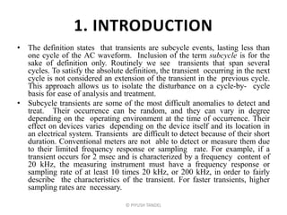
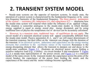
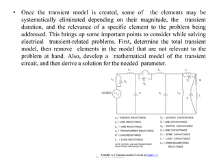
POWER QUALITY
Prof. Piyush N. Tandel
Electrical Engineering
MGITER,Navsari
Chapter . 3
Electrical Transients
© PIYUSH TANDEL
1. INTRODUCTION
• The definition states that transients are subcycle events, lasting less than
one cycle of the AC waveform. Inclusion of the term subcycle is for the
sake of definition only. Routinely we see transients that span several
cycles. To satisfy the absolute definition, the transient occurring in the next
cycle is not considered an extension of the transient in the previous cycle.
This approach allows us to isolate the disturbance on a cycle-by- cycle
basis for ease of analysis and treatment.
• Subcycle transients are some of the most difficult anomalies to detect and
treat. Their occurrence can be random, and they can vary in degree
depending on the operating environment at the time of occurrence. Their
effect on devices varies depending on the device itself and its location in
an electrical system. Transients are difficult to detect because of their short
duration. Conventional meters are not able to detect or measure them due
to their limited frequency response or sampling rate. For example, if a
transient occurs for 2 msec and is characterized by a frequency content of
20 kHz, the measuring instrument must have a frequency response or
sampling rate of at least 10 times 20 kHz, or 200 kHz, in order to fairly
describe the characteristics of the transient. For faster transients, higher
sampling rates are necessary.
© PIYUSH TANDEL
• Many different terms are associated with transients, such as spikes, bumps,
power pulses, impulses, and surges. While some of these terms may indeed
describe a particular transient, such terms are not recommended due to
their ambiguity. We will use the term transient to denote all subcycle events
and ascribe certain charac teristics to these events, such as overvoltage,
notch, noise, and ring. It may be that what we call transient is not as
important as remembering that the underlying causes of the various
transient events differ, as do the cures for the ill effects produced by the
transients.
• Why is an understanding of the transient phenomenon important? Problems
arise because of the sensitivity of the microelectronic devices and circuits
that make up the control elements of the power system. The microprocess
controller is the nerve center of every present-day manufacturing or
commercial facility. Medical electronic instruments used in healthcare
facilities are becoming more sophisticated and at the same time
increasingly susceptible to Why is an understanding of the transient
phenomenon important? Large electromagnetic devices such as
transformers and motors are practically impervious to the effects of
transients. Problems arise because of the sensitivity of the microelectronic
devices and circuits that make up the control elements of the power system.
The microprocess controller is the nerve center of every present-day
manufacturing or commercial facility. Medical electronic instruments used
in healthcare facilities are becoming more sophisticated and at the same
time increasingly susceptible to electrical transients.
© PIYUSH TANDEL
2. TRANSIENT SYSTEM MODEL
• Steady-state systems are the opposite of transient systems. In steady state, the
operation of a power system is characterized by the fundamental frequency or by some
low-frequency harmonic of the fundamental frequency. The three passive parameters
of the system — resistance (R), inductance (L), and capacitance (C) — determine how
the steady-state system will respond when under the influence of an applied voltage.
This situation is somewhat analogous to the steady-state model, in which thermal
energy supplied is equal to energy stored plus energy dissipated, and by using
traditional laws of physics the temperature rise of devices can be accurately calculated.
• However, in a transient state, traditional laws of equilibrium do not apply. The
circuit model of a transient electrical system will appear considerably different from
the steady-state model. Passive parameters R, L, and C are still major determinants of
the transient response, but their effect on the transient can change with the duration of
the transient. In an electrical system, inductance and capacitance are the energy-storing
elements that contribute to the oscillatory nature of the transient. Resistance is the
energy-dissipating element that allows the transient to dampen out and decay to the
steady-state condition. Figure 3.1 illustrates an electrical power source feeding a
resistive–inductive load (e.g., a motor) via circuit breaker S and transformer T. Figure
3.2 is a steady-state representation of the power circuit, and Figure 3.3 is a transient
model of the same circuit. In the transient model, the capacitance across the poles of the
circuit breaker, the capacitance of the power lines feeding the motor, and the
capacitance of the source and the motor windings become significant.
© PIYUSH TANDEL
© PIYUSH TANDEL
© PIYUSH TANDEL
• Once the transient model is created, some of the elements may be
systematically eliminated depending on their magnitude, the transient
duration, and the relevance of a specific element to the problem being
addressed. This brings up some important points to consider while solving
electrical transient-related problems. First, determine the total transient
model, then remove elements in the model that are not relevant to the
problem at hand. Also, develop a mathematical model of the transient
circuit, and then derive a solution for the needed parameter.
© PIYUSH TANDEL
3. EXAMPLES OF TRANSIENT MODELS AND
THEIR RESPONSE
• Some examples of transient models and transient response are included in
this section. The examples are simple but nonetheless are intended to
provide the reader with a better grasp of the basics of electrical transients.
© PIYUSH TANDEL
3.1. APPLICATION OF DC VOLTAGE TO
A CAPACITOR
© PIYUSH TANDEL
• Figure 3.4 depicts a capacitor to which a DC voltage (V ) is suddenly applied.
Figure 3.5 represents in graphical form the transient response for the current and
voltage across the capacitor. The expressions for VC and IC assume that the capacitor
has zero initial charge:
• VC = V(1 – e–t/RC) (3.1)
• IC = (V/R)e–t/RC (3.2)
• where RC is the time constant (T) of the resistance–capacitance circuit and is
expressed in seconds. The time constant is the time it would take for an exponentially
decaying parameter to reach a value equal to 36.79% of the initial value. This is
explained by noting that the parameter would be reduced to a value given by 1/e1 or
0.3679 of the initial value. In a time interval equal to two time constants, the
parameter will be reduced to 1/e2 or 13.5% of the initial value. After five time
constants, the parameter will be reduced to 0.67% of the initial value. As time
increases, the value e–t/T becomes smaller and smaller and approaches zero. In this
example, the current through the capacitor is V/R at time t = 0. At time t = T, the
current will diminish to 0.3679(V/R); at time t = 2T, the current will be 0.1353(V/R),
and so on.
• In the same example, if the capacitance has an initial voltage of +V0, then the
expressions become:
• VC = V – (V – V0)e–t/RC (3.3)
• IC = [(V – V0)/R]e–t/RC (3.4)
© PIYUSH TANDEL
3.2 APPLICATION OF DC VOLTAGE TO AN
INDUCTOR
© PIYUSH TANDEL
• Figure 3.6 shows an inductor with R representing the resistance of the
connecting wires and the internal resistance of the inductor. The variation
of voltage and the current in the inductor are shown in Figure 3.7 and
expressed by:
• At time t = 0, the voltage across the inductor is V; in an ideal
inductor, current cannot change instantly, so the applied voltage
appears across the inductor. At time t = , voltage across the inductor
is zero. The current through the ideal inductor at time t = 0, and at
time t =  the current through the inductor is equal to V/R.
• For an inductive circuit, the time constant T in seconds is equal to
L/R, and the expressions for VL and IL become:
© PIYUSH TANDEL
VL = Ve–tR/L
IL = (V/R)(1 – e–tR/L)
VL = Ve–t/T
IL = (V/R) (1 – e–t/T)
© PIYUSH TANDEL
• The significance of the time constant is again as indicated under the
discussion for capacitors. In this example, the voltage across the inductor
after one time constant will equal 0.3679 V; in two time constants, 0.1353 V;
and so on.
• The significance of the time constant T in both capacitive and inductive
circuits is worth emphasizing. The time constant reflects how quickly a
circuit can recover when subjected to transient application of voltage or
current. Consider Eq. (3.1), which indicates how voltage across a capacitor
would build up when subjected to a sudden application of voltage V. The
larger the time constant RC, the slower the rate of voltage increase across the
capacitor. If we plot voltage vs. time characteristics for various values of time
constant T, the family of graphs will appear as shown in Figure 3.8. In
inductive circuits, the time constant indicates how quickly current can build
up through an inductor when a switch is closed and also how slowly current
will decay when the inductive circuit is opened. The time constant is an
important parameter in the transient analysis of power line disturbances.
• The L–C combination, whether it is a series or parallel configuration, is an
oscillatory circuit, which in the absence of resistance as a damping agent will
oscillate indefinitely. Because all electrical circuits have resistance associated
with them, the oscillations eventually die out. The frequency of the
oscillations is called the natural frequency, fO. For the L–C circuit:
fO = 1/2 LC
© PIYUSH TANDEL
• In the L–C circuit, the voltage across the capacitor might appear as shown
in Figure 3.9. The oscillations are described by the Eq. which gives the
voltage across the capacitance as:
VC = V – (V – VCO) cosOt
• where V is the applied voltage, VCO is the initial voltage across the
capacitor, and O is equal to 2fO.
© PIYUSH TANDEL
• Depending on the value and polarity of VCO, a voltage of three times the
applied voltage may be generated across the capacitor. The capacitor also
draws a considerable amount of oscillating currents. The oscillations occur at
the characteristic frequency, which can be high depending on the value of L
and C. A combination of factors could result in capacitor or inductor failure.
Most power systems have some combination of inductance and capacitance
present. Capacitance might be that of the power factor correction devices in
an electrical system, and inductance might be due to the power transformer
feeding the electrical system.
• The examples we saw are for L–C circuits supplied from a direct current
source. What happens when an L–C circuit is excited by an alternating
current source? Once again, oscillatory response will be present. The
oscillatory waveform superimposes on the fundamental waveform until the
damping forces sufficiently attenuate the oscillations. At this point, the
system returns to normal operation. In a power system characterized by low
resistance and high values of L and C, the effects would be more damaging
than if the system were to have high resistance and low L and C because the
natural frequencies are high when the values of L and C are low. The
resistance of the various components that make up the power system is also
high at the higher frequencies due to the skin effect, which provides better
damping characteristics. In all cases, we are concerned about not only the
welfare of the capacitor bank or the transformer but also the impact such
oscillations would have on other equipment or devices in the electrical
system.
© PIYUSH TANDEL
3.4 POWER SYSTEM TRANSIENT MODEL
• At power frequencies, electrical systems may be represented by
lumped parameters of R, L, and C. Figure 3.10 shows a facility
power system fed by 10 miles of power lines from a utility
substation where the power is transformed from 12.47 kV to 480 V
to supply various loads, including a power factor correction
capacitor bank. Reasonable accuracy is obtained by representing the
power system components by their predominant electrical
characteristics, as shown in Figure 3.10. Such a representation
simplifies the calculations at low frequencies. To obtain higher
accuracy as the frequency goes up, the constants are divided up and
grouped to form the  or T configurations shown in Figure 3.11; the
computations get tedious, but more accurate results are obtained.
Yet, at high frequencies the power system should be represented by
distributed parameters, as shown in Figure 3.12. In Figure 3.12, r, l,
and c represent the resistance, inductance, and capacitance,
respectively, for the unit distance. The reason for the distributed
parameter approach is to produce results that more accurately
represent the response of a power system to high-frequency
transient phenomena.
© PIYUSH TANDEL
© PIYUSH TANDEL
© PIYUSH TANDEL
• The wavelength of a periodic waveform is given by:
 = C/f
• where C is the velocity of light in vacuum and is equal to 300  106 msec or
186,400 miles/sec. For 60-Hz power frequency signals,  is equal to 3106 miles; for a
1-MHz signal,  is equal to 393 ft.
• All alternating current electrical signals travel on a conducting medium such as
overhead power lines or underground cables. When a signal reaches the end of the
wiring, it reflects back. Depending on the polarity and the phase angle of the reflected
wave, the net amplitude of the composite waveform can have a value between zero
and twice the value of the incident wave. Typically, at 1/4 wavelength and odd
multiples of 1/4 wavelength, the reflected wave becomes equal in value but opposite
in sign to the incident wave. The incident and the reflected waves cancel out, leaving
zero net signal. The cable, in essence, acts like a high-impedance circuit. For transient
phenomena occurring at high frequencies, however, even comparatively short lengths
of wire might be too long to be effective.
• Several quantities characterize the behavior of power lines as far as transient
response is concerned. One important quantity is the characteristic impedance,
expressed as:
ZO =L/C 
• In a power line that has no losses, the voltage and the current are linked by the
characteristic impedance ZO.
© PIYUSH TANDEL
• Another important characteristic of power systems is the natural frequency,
which allows us to calculate the frequency of a disturbance produced in the
L–C circuit when it is excited by a voltage or current signal. Why is this
important? Transient phenomena are very often oscillatory, and the
frequencies encountered are higher than the power frequency. By knowing the
circuit constants L and C and the amplitude of the exciting voltage and
current, the response of a transient circuit might be determined with
reasonable accuracy. Also, when two circuits or power lines are connected
together, the characteristic impedance of the individual circuits determines
how much of the transient voltage or current will be reflected back and what
portion will be refracted or passed through the junction to the second circuit.
This is why, in transient modeling, impedance mismatches should be
carefully managed to minimize large voltage or current buildups. The natural
frequency is given by:
fO = 1/2 LC
© PIYUSH TANDEL
• Because any electrical signal transmission line has inductance and
capacitance associated with it, it also has a natural frequency. The
phenomenon of resonance occurs when the capacitive and inductive
reactances of the circuit become equal at a given frequency. In
transmission line theory, the resonant frequency is referred to as the
characteristic frequency. Resonance in a parallel circuit is
characterized by high impedance at the resonant frequency, as shown
in Figure 3.13. The electrical line or cable has a characteristic
resonance frequency that would allow the cable to appear as a large
impedance to the flow of current. These typically occur at frequencies
corresponding to 1/4 wavelengths. The significance of this becomes
apparent when cables are used for carrying high-frequency signals or
as ground reference conductors. Conductor lengths for these
applications have to be kept short to eliminate operation in the
resonance regions; otherwise, significant signal attenuation could
result. If the cable is used as a ground reference conductor, the
impedance of the cable could render it less than effective.
• The velocity of propagation (v) indicates how fast a signal may
travel in a medium and is given by:
• v = 1/ 
© PIYUSH TANDEL
© PIYUSH TANDEL
• where  is the permeability of the medium and  is the dielectric
permittivity. For example, in a vacuum, the permeability =  = 410–
7 H/m, and the dielectric permittivity =  = 8.85  10–12 F/m.
Therefore,
v = 1/(410–7  8.85  10–12)  300  106 msec = velocity of light
• For other media, such as insulated cables or cables contained in
magnetic shields (conduits, etc.), the velocity of propagation will be
slower, as these items are no longer characterized by the free air
qualities of  and .
• The quantities ZO, fO, and v are important for examining transient
phenomenon because high-speed, high-frequency events can travel
through a conductive path (wire) or may be coupled to adjacent
circuits by propagation through a dielectric medium. How effective
the path is at coupling the transient depends on these factors.
© PIYUSH TANDEL
3.5 TYPES AND CAUSES OF TRANSIENTS
• Transients are disturbances that occur for a very short duration (less than a
cycle), and the electrical circuit is quickly restored to original operation
provided no damage has occurred due to the transient. An electrical transient
is a cause-and-effect phenomenon. For transients to occur, there must be a
cause. While they may be many, this section will look at some of the more
common causes of transients:
•Atmospheric phenomena (lightning, solar flares, geomagnetic disturbances)
•Switching loads on or off
•Interruption of fault currents
•Switching of power lines
•Switching of capacitor banks
© PIYUSH TANDEL
3.5.1 ATMOSPHERIC CAUSES
• Over potential surge due to lightning discharge is the most common natural
cause of electrical equipment failure. The phenomenon of lighting strike
can be described as follows. A negative charge builds up on a cloud, as
indicated in Figure 3.14. A corresponding positive charge can build up on
the surface of the earth. A voltage difference of hundreds of millions of
volts can exist between the cloud and the earth due to the opposing
charges. When the voltage exceeds the breakdown potential of air (about 3
 106 V/m or 75 kV/inch), a lightning flash occurs. The exact physics of
the lightning phenomenon will not be discussed here, as it is sufficient to
know that a lightning strike can typically produce a voltage rise in about 1
or 2 sec that can decline to a value of 50% of the peak voltage in
approximately 50 to 100 sec. A typical lightning impulse wave might
appear as shown in Figure 3.15. A common misconception is that a direct
lightning strike is needed to produce destructive over voltages. In fact, it is
rare that a failure in an electrical system is due to a direct lightning strike.
More often, the electrical and magnetic fields caused by indirect lightning
discharge induce voltages in the power lines that result in device failures.
Also, lightning discharge current flowing through the earth creates a
potential difference between the power lines and ground and in extreme
cases causes equipment failure.
© PIYUSH TANDEL
© PIYUSH TANDEL
© PIYUSH TANDEL
• Isolation transformers provide limited protection from lightning
strikes. Because lightning is a short-duration, high-frequency
phenomenon, a portion of the lightning energy will couple directly
from the primary winding to the secondary winding of the transformer
through the interwinding capacitance. This is why equipment sup-
plied from the low-voltage winding of a transformer that is exposed to
lightning energy is also at risk. The amount of voltage that will be
coupled through the transformer will depend on the transformer
interwinding capacitance itself. The higher the capacitance, the higher
the transient energy coupled to the secondary. Transformers provided
with a grounded shield between the primary and the secondary
windings provide better protection against lightning energy present at
the trans- former primary winding.
• Lightning arresters, when properly applied, can provide protection
against lightning-induced low voltages. Arresters have a well-defined
conduction voltage below which they are ineffective. This voltage
depends on the rating of the arrester itself. For optimum protection, the
arrester voltage should be matched to the lightning impulse withstand
of the equipment being protected. Table 3.1 provides typical voltage
discharge characteristics of arresters for various voltage classes.
© PIYUSH TANDEL
© PIYUSH TANDEL
3.5.2 SWITCHING LOADS ON OR OFF
• Switching normal loads in a facility can produce transients. The majority of plant
loads draw large amounts of current when initially turned on. Transformers draw
inrush currents that range between 10 and 15 times their normal full-load current.
This current lasts between 5 and 10 cycles. Alternating current motors draw starting
currents that vary between 500 and 600% of the normal full-load running current.
Fluorescent lights draw inrush currents when first turned on. Large current drawn
through the impedance of the power system sets up transient voltages that affect
electrical components sensitive to sags, subcycle oscillations, or voltage notch.
There are instances when conditions are such that harmonic frequency currents in
the inrush current interact with the power system inductance and capacitance and
cause resonance conditions to develop. During resonance, substantial over voltages
and over- currents might develop. In the strict sense, these are not subcycle events
and therefore may not be classified as transients, but their effects are nonetheless
very detrimental.
• When discussing inductive coupling due to transient current, the loop area of the
susceptible circuit should not be overlooked (see Figure 3.16), as the larger the area
of the loop, the higher the noise voltage induced in the susceptible circuit. In
Figure 3.16, the voltage induced in circuit 2 depends on the magnetic field linking
the circuit; the larger the loop area, the larger the flux linkage and, therefore, the
higher the noise voltage induced in circuit 2. Twisted pairs of wires minimize the
loop area and reduce noise voltage pickup, thus signal and data circuits for sensitive,
low-level signal applications installed in close proximity to power wires should use
twisted sets of wires to reduce noise coupling.
© PIYUSH TANDEL
© PIYUSH TANDEL
• So far we have examined the effects of switching power to loads during
normal operation. Switching power off also generates transients due to the
fact that all devices carrying electrical current have inductances (L)
associated with them. The current flowing in an inductive device cannot
abruptly change when the circuit is opened. The voltage produced in an
electrical device due to a sudden change of current is given by:
• e = L  di/dt
• where di/dt is the rate change of current and L is the inductance associated
with the device.
• For example, if 50 A of current flowing through a coil of inductance L = 20
mH drops to zero in 2 msec, then the voltage generated across the coil is
given by:
• E = (20  10–3  50)/(2  10–3) = 500 V
© PIYUSH TANDEL
3.5.3 INTERRUPTION OF FAULT CIRCUITS
• During fault conditions, large currents are generated in an electrical
system. The fault currents are interrupted by overcurrent devices such as
circuit breakers or fuses. Figure 3.17 shows a simplified electrical circuit
where an electrical fault is cleared by a circuit breaker. C represents the
capacitance of the electrical system up to the point where the overcurrent
device is present. Interruption of the fault current generates overvoltage
impulse in the electrical system, and the magnitude of the voltage depends
on the amount of fault current and the speed with which the fault is
interrupted. Older air circuit breakers with slower speed of interruption
produce lower impulse voltages than vacuum or SF6 breakers, which operate
at much faster speeds during a fault. While using vacuum or SF6 technology
to clear a fault quickly and thereby limit damage to equipment is an
important advantage, a price is paid by the generation of higher level voltage
transients.
© PIYUSH TANDEL
© PIYUSH TANDEL
• Once the fault is interrupted, the generated voltage impulse can
interact with the inductance and capacitance of the electrical system
and produce oscillation at a frequency much higher than the
fundamental frequency. The oscillations are slowly damped out by
the resistance associated with the system. The response of the
system might appear somewhat like what is shown in Figure 3.18.
The voltage can build up to levels equal to twice the peak value of
the voltage waveform. The overvoltage and associated oscillations
are harmful to electrical devices.
• A very serious case of over voltages and oscillations occurs when the
overcurrent device is supplied from overhead power lines that
connect to long lengths of under- ground cables. Underground
cables have substantial capacitance to ground. The combination of
the inductance due to overhead lines and capacitance due to under-
ground cables could generate high levels of overvoltage and
prolonged oscillations at low frequencies. Such transients are very
damaging to transformers, cables, and motors supplied from the
lines. In extreme cases, voltages as high as three to four times the
AC peak voltage may be generated.
© PIYUSH TANDEL
3.5.4 CAPACITOR BANK SWITCHING
• One of the more common causes of electrical transients is switching of
capacitor banks in power systems. Electrical utilities switch capacitor
banks during peak load hours to offset the lagging kVAR demand of the
load. The leading kVARs drawn by the capacitor banks offset the lagging
kVAR demand of the load, reducing the net kVA load on the circuit.
Switching of capacitor banks is accompanied by a surge of current which is
initially limited by the characteristic impedance of the power system and
resistance of the line. A sharp reduction in the voltage is followed by a
voltage rise, which decays by oscillation at a frequency determined by the
inductance and capacitance of the circuit. Several cases of power system
component failures and malfunctions due to capacitor bank switching
operations have been seen by the author. Typically, the voltage rise due to
capacitor switching operation can attain values 1.5 to 2 times the nominal
voltage. Power equipment can withstand only a limited number of
exposures to such rises in voltage magnitude. With time, the insulation
systems of such devices weaken, and a point is reached when the devices
can fail. In one particular instance, two power distribution transformers
failed at the same time; the cause was traced to large capacitor bank
switching operations by the utility at a substation located adjacent to the
affected facility.
© PIYUSH TANDEL
© PIYUSH TANDEL
3.6 EXAMPLES OF TRANSIENT
WAVEFORMS
© PIYUSH TANDEL
1. MOTOR START TRANSIENT
• Figure 3.19 shows a transient produced when a 50-hp
induction motor with integral power factor correction was
started across the line. The notch in the voltage wave- form
at the instant of starting was produced by the presence of
the capacitor. The quick voltage recovery was followed by
ringing characteristics. The transient lasted less than half of
a cycle, but it was sufficient to affect the operation of large
chillers located nearby which contained solid-state starters
with sensitive voltage-sensing circuitry. Because of the
severity of the motor-starting transient, the chillers started
to shut down. In a situation such as this, it is often prudent
to apply correction to the sensitive circuitry rather than try
to eliminate the problem itself or apply cor- rection to the
power system as a whole.
© PIYUSH TANDEL
2. POWER FACTOR CORRECTION CAPACITOR
SWITCHING TRANSIENT
• Figure 3.20 shows the transient voltage response at the main electrical
switchboard for a commercial building due to capacitor bank switching by
the utility. A moderate rise in system voltage is followed by ringing at the
characteristic frequency of the utility source inductive reactance and
capacitance due to the power factor correction equipment.
© PIYUSH TANDEL
3. MEDIUM VOLTAGE CAPACITOR BANK
SWITCHING TRANSIENT
• The transient shown in Figure 3.21 was the result of a 5-MVAR
capacitor bank switching at an industrial facility. The facility
suffered from poor power factor due to plant loads which
necessitated connection of the capacitor bank. The initial rise in
voltage reached peak amplitude equal to 160% of the system
nominal peak voltage. This practice had been going on in this
facility for approximately 5 years before failures were observed in
underground cables and a power transformer. At this point, the
electrical system in the facility was monitored for transient voltages
by installing power quality analyzers at select locations. Once the
nature of the transients and their cause were determined, corrective
steps were taken to retrofit the capacitor bank with pre-insertion
resistors, which helped to attenuate the amplitude of the impulse.
Also, all replacement equipment at the facility was specified to be
of a higher basic insulation level (BIL) than the minimum specified
in standards.
© PIYUSH TANDEL
© PIYUSH TANDEL
4. VOLTAGE NOTCH DUE TO
UNINTERRUPTIBLE POWER SOURCE UNIT
• Typically, we associate voltage notches with adjustable speed
drives. Voltage notches are also common with the outputs of
uninterruptible power source (UPS) units due to power
electronic switching circuitry associated with the UPS units.
Unless pro- vided with wave-shaping and filtering circuitry,
the output of the UPS can contain substantial notches. Figure
3.22 shows the output waveform of a UPS unit supplying 480-
V output to a computer center at a financial institution. If the
notch levels become excessive, problems can arise in the
operation of sensitive communication or data-processing
loads. The voltage notch phenomenon is a repetitive event.
Even though we defined transients as subcycle events, the
repetitive notching shown is included in this section for the
sake of completeness.
© PIYUSH TANDEL
© PIYUSH TANDEL
5. NEUTRAL VOLTAGE SWING
• The event shown in Figure 3.23 was observed in a computer
laboratory at a university. Normally, neutral voltage should be
within 0.5 V with respect to the ground. This is because in a four-
wire power distribution system the neutral of the power source is
connected to the ground at the source. This tends to hold the neutral
potential close to the ground. In a typical building, neutral-to-
ground voltages become higher as we move away from the source
feeding the facility. In some instances, depending on the loads and
the distance between the source and the load, neutral-to-ground
voltage can measure 2 to 3 V. The case illustrated by Figure 3.23 is
an extreme one where neutral-to-ground voltages reached levels
higher than 10 V. The computer laboratory experienced many
problems with the computers locking up, in some instances during
critical times when tests were being administered to the students.
© PIYUSH TANDEL
© PIYUSH TANDEL
6. SUDDEN APPLICATION OF VOLTAGE
• Fast rise time transients are produced when voltage is suddenly applied to a
load. Figure 3.24 shows an example of 480 V being applied to the primary
of a power distribution transformer. Typical waveform characteristics
include fast rise time and ringing due to the inductance and capacitance of
the load circuitry. Normally, power system should ride through such
occurrences, but, if the load circuit includes capacitor banks or power
supplies with capacitors, large inrush currents may be produced with
possible overcurrent protection operation. In situations where the capacitors
have an initial charge present, some overvoltage events may be produced.
© PIYUSH TANDEL
© PIYUSH TANDEL
7. SELF-PRODUCED TRANSIENTS
• Some machines by nature generate transients that can affect machine
operation if they contain sensitive circuits. Figure 3.25 shows a
waveform produced by a food- processing machine. The transients
occurred several times each day as the machine automatically
turned on and off. Severe transients caused the machine to go into a
lockout mode which required the operator to manually reset the
machine. The problem was fixed by providing a dedicated circuit of
low impedance for the machine. This reduced the transient to levels
that could be lived with.
© PIYUSH TANDEL
© PIYUSH TANDEL
End of Chapter 3
© PIYUSH TANDEL

Chep 03 Electrical transient

  • 1.
    POWER QUALITY Prof. PiyushN. Tandel Electrical Engineering MGITER,Navsari Chapter . 3 Electrical Transients © PIYUSH TANDEL
  • 2.
    1. INTRODUCTION • Thedefinition states that transients are subcycle events, lasting less than one cycle of the AC waveform. Inclusion of the term subcycle is for the sake of definition only. Routinely we see transients that span several cycles. To satisfy the absolute definition, the transient occurring in the next cycle is not considered an extension of the transient in the previous cycle. This approach allows us to isolate the disturbance on a cycle-by- cycle basis for ease of analysis and treatment. • Subcycle transients are some of the most difficult anomalies to detect and treat. Their occurrence can be random, and they can vary in degree depending on the operating environment at the time of occurrence. Their effect on devices varies depending on the device itself and its location in an electrical system. Transients are difficult to detect because of their short duration. Conventional meters are not able to detect or measure them due to their limited frequency response or sampling rate. For example, if a transient occurs for 2 msec and is characterized by a frequency content of 20 kHz, the measuring instrument must have a frequency response or sampling rate of at least 10 times 20 kHz, or 200 kHz, in order to fairly describe the characteristics of the transient. For faster transients, higher sampling rates are necessary. © PIYUSH TANDEL
  • 3.
    • Many differentterms are associated with transients, such as spikes, bumps, power pulses, impulses, and surges. While some of these terms may indeed describe a particular transient, such terms are not recommended due to their ambiguity. We will use the term transient to denote all subcycle events and ascribe certain charac teristics to these events, such as overvoltage, notch, noise, and ring. It may be that what we call transient is not as important as remembering that the underlying causes of the various transient events differ, as do the cures for the ill effects produced by the transients. • Why is an understanding of the transient phenomenon important? Problems arise because of the sensitivity of the microelectronic devices and circuits that make up the control elements of the power system. The microprocess controller is the nerve center of every present-day manufacturing or commercial facility. Medical electronic instruments used in healthcare facilities are becoming more sophisticated and at the same time increasingly susceptible to Why is an understanding of the transient phenomenon important? Large electromagnetic devices such as transformers and motors are practically impervious to the effects of transients. Problems arise because of the sensitivity of the microelectronic devices and circuits that make up the control elements of the power system. The microprocess controller is the nerve center of every present-day manufacturing or commercial facility. Medical electronic instruments used in healthcare facilities are becoming more sophisticated and at the same time increasingly susceptible to electrical transients. © PIYUSH TANDEL
  • 4.
    2. TRANSIENT SYSTEMMODEL • Steady-state systems are the opposite of transient systems. In steady state, the operation of a power system is characterized by the fundamental frequency or by some low-frequency harmonic of the fundamental frequency. The three passive parameters of the system — resistance (R), inductance (L), and capacitance (C) — determine how the steady-state system will respond when under the influence of an applied voltage. This situation is somewhat analogous to the steady-state model, in which thermal energy supplied is equal to energy stored plus energy dissipated, and by using traditional laws of physics the temperature rise of devices can be accurately calculated. • However, in a transient state, traditional laws of equilibrium do not apply. The circuit model of a transient electrical system will appear considerably different from the steady-state model. Passive parameters R, L, and C are still major determinants of the transient response, but their effect on the transient can change with the duration of the transient. In an electrical system, inductance and capacitance are the energy-storing elements that contribute to the oscillatory nature of the transient. Resistance is the energy-dissipating element that allows the transient to dampen out and decay to the steady-state condition. Figure 3.1 illustrates an electrical power source feeding a resistive–inductive load (e.g., a motor) via circuit breaker S and transformer T. Figure 3.2 is a steady-state representation of the power circuit, and Figure 3.3 is a transient model of the same circuit. In the transient model, the capacitance across the poles of the circuit breaker, the capacitance of the power lines feeding the motor, and the capacitance of the source and the motor windings become significant. © PIYUSH TANDEL
  • 5.
  • 6.
  • 7.
    • Once thetransient model is created, some of the elements may be systematically eliminated depending on their magnitude, the transient duration, and the relevance of a specific element to the problem being addressed. This brings up some important points to consider while solving electrical transient-related problems. First, determine the total transient model, then remove elements in the model that are not relevant to the problem at hand. Also, develop a mathematical model of the transient circuit, and then derive a solution for the needed parameter. © PIYUSH TANDEL
  • 8.
    3. EXAMPLES OFTRANSIENT MODELS AND THEIR RESPONSE • Some examples of transient models and transient response are included in this section. The examples are simple but nonetheless are intended to provide the reader with a better grasp of the basics of electrical transients. © PIYUSH TANDEL
  • 9.
    3.1. APPLICATION OFDC VOLTAGE TO A CAPACITOR © PIYUSH TANDEL
  • 10.
    • Figure 3.4depicts a capacitor to which a DC voltage (V ) is suddenly applied. Figure 3.5 represents in graphical form the transient response for the current and voltage across the capacitor. The expressions for VC and IC assume that the capacitor has zero initial charge: • VC = V(1 – e–t/RC) (3.1) • IC = (V/R)e–t/RC (3.2) • where RC is the time constant (T) of the resistance–capacitance circuit and is expressed in seconds. The time constant is the time it would take for an exponentially decaying parameter to reach a value equal to 36.79% of the initial value. This is explained by noting that the parameter would be reduced to a value given by 1/e1 or 0.3679 of the initial value. In a time interval equal to two time constants, the parameter will be reduced to 1/e2 or 13.5% of the initial value. After five time constants, the parameter will be reduced to 0.67% of the initial value. As time increases, the value e–t/T becomes smaller and smaller and approaches zero. In this example, the current through the capacitor is V/R at time t = 0. At time t = T, the current will diminish to 0.3679(V/R); at time t = 2T, the current will be 0.1353(V/R), and so on. • In the same example, if the capacitance has an initial voltage of +V0, then the expressions become: • VC = V – (V – V0)e–t/RC (3.3) • IC = [(V – V0)/R]e–t/RC (3.4) © PIYUSH TANDEL
  • 11.
    3.2 APPLICATION OFDC VOLTAGE TO AN INDUCTOR © PIYUSH TANDEL
  • 12.
    • Figure 3.6shows an inductor with R representing the resistance of the connecting wires and the internal resistance of the inductor. The variation of voltage and the current in the inductor are shown in Figure 3.7 and expressed by: • At time t = 0, the voltage across the inductor is V; in an ideal inductor, current cannot change instantly, so the applied voltage appears across the inductor. At time t = , voltage across the inductor is zero. The current through the ideal inductor at time t = 0, and at time t =  the current through the inductor is equal to V/R. • For an inductive circuit, the time constant T in seconds is equal to L/R, and the expressions for VL and IL become: © PIYUSH TANDEL VL = Ve–tR/L IL = (V/R)(1 – e–tR/L) VL = Ve–t/T IL = (V/R) (1 – e–t/T)
  • 13.
  • 14.
    • The significanceof the time constant is again as indicated under the discussion for capacitors. In this example, the voltage across the inductor after one time constant will equal 0.3679 V; in two time constants, 0.1353 V; and so on. • The significance of the time constant T in both capacitive and inductive circuits is worth emphasizing. The time constant reflects how quickly a circuit can recover when subjected to transient application of voltage or current. Consider Eq. (3.1), which indicates how voltage across a capacitor would build up when subjected to a sudden application of voltage V. The larger the time constant RC, the slower the rate of voltage increase across the capacitor. If we plot voltage vs. time characteristics for various values of time constant T, the family of graphs will appear as shown in Figure 3.8. In inductive circuits, the time constant indicates how quickly current can build up through an inductor when a switch is closed and also how slowly current will decay when the inductive circuit is opened. The time constant is an important parameter in the transient analysis of power line disturbances. • The L–C combination, whether it is a series or parallel configuration, is an oscillatory circuit, which in the absence of resistance as a damping agent will oscillate indefinitely. Because all electrical circuits have resistance associated with them, the oscillations eventually die out. The frequency of the oscillations is called the natural frequency, fO. For the L–C circuit: fO = 1/2 LC © PIYUSH TANDEL
  • 15.
    • In theL–C circuit, the voltage across the capacitor might appear as shown in Figure 3.9. The oscillations are described by the Eq. which gives the voltage across the capacitance as: VC = V – (V – VCO) cosOt • where V is the applied voltage, VCO is the initial voltage across the capacitor, and O is equal to 2fO. © PIYUSH TANDEL
  • 16.
    • Depending onthe value and polarity of VCO, a voltage of three times the applied voltage may be generated across the capacitor. The capacitor also draws a considerable amount of oscillating currents. The oscillations occur at the characteristic frequency, which can be high depending on the value of L and C. A combination of factors could result in capacitor or inductor failure. Most power systems have some combination of inductance and capacitance present. Capacitance might be that of the power factor correction devices in an electrical system, and inductance might be due to the power transformer feeding the electrical system. • The examples we saw are for L–C circuits supplied from a direct current source. What happens when an L–C circuit is excited by an alternating current source? Once again, oscillatory response will be present. The oscillatory waveform superimposes on the fundamental waveform until the damping forces sufficiently attenuate the oscillations. At this point, the system returns to normal operation. In a power system characterized by low resistance and high values of L and C, the effects would be more damaging than if the system were to have high resistance and low L and C because the natural frequencies are high when the values of L and C are low. The resistance of the various components that make up the power system is also high at the higher frequencies due to the skin effect, which provides better damping characteristics. In all cases, we are concerned about not only the welfare of the capacitor bank or the transformer but also the impact such oscillations would have on other equipment or devices in the electrical system. © PIYUSH TANDEL
  • 17.
    3.4 POWER SYSTEMTRANSIENT MODEL • At power frequencies, electrical systems may be represented by lumped parameters of R, L, and C. Figure 3.10 shows a facility power system fed by 10 miles of power lines from a utility substation where the power is transformed from 12.47 kV to 480 V to supply various loads, including a power factor correction capacitor bank. Reasonable accuracy is obtained by representing the power system components by their predominant electrical characteristics, as shown in Figure 3.10. Such a representation simplifies the calculations at low frequencies. To obtain higher accuracy as the frequency goes up, the constants are divided up and grouped to form the  or T configurations shown in Figure 3.11; the computations get tedious, but more accurate results are obtained. Yet, at high frequencies the power system should be represented by distributed parameters, as shown in Figure 3.12. In Figure 3.12, r, l, and c represent the resistance, inductance, and capacitance, respectively, for the unit distance. The reason for the distributed parameter approach is to produce results that more accurately represent the response of a power system to high-frequency transient phenomena. © PIYUSH TANDEL
  • 18.
  • 19.
  • 20.
    • The wavelengthof a periodic waveform is given by:  = C/f • where C is the velocity of light in vacuum and is equal to 300  106 msec or 186,400 miles/sec. For 60-Hz power frequency signals,  is equal to 3106 miles; for a 1-MHz signal,  is equal to 393 ft. • All alternating current electrical signals travel on a conducting medium such as overhead power lines or underground cables. When a signal reaches the end of the wiring, it reflects back. Depending on the polarity and the phase angle of the reflected wave, the net amplitude of the composite waveform can have a value between zero and twice the value of the incident wave. Typically, at 1/4 wavelength and odd multiples of 1/4 wavelength, the reflected wave becomes equal in value but opposite in sign to the incident wave. The incident and the reflected waves cancel out, leaving zero net signal. The cable, in essence, acts like a high-impedance circuit. For transient phenomena occurring at high frequencies, however, even comparatively short lengths of wire might be too long to be effective. • Several quantities characterize the behavior of power lines as far as transient response is concerned. One important quantity is the characteristic impedance, expressed as: ZO =L/C  • In a power line that has no losses, the voltage and the current are linked by the characteristic impedance ZO. © PIYUSH TANDEL
  • 21.
    • Another importantcharacteristic of power systems is the natural frequency, which allows us to calculate the frequency of a disturbance produced in the L–C circuit when it is excited by a voltage or current signal. Why is this important? Transient phenomena are very often oscillatory, and the frequencies encountered are higher than the power frequency. By knowing the circuit constants L and C and the amplitude of the exciting voltage and current, the response of a transient circuit might be determined with reasonable accuracy. Also, when two circuits or power lines are connected together, the characteristic impedance of the individual circuits determines how much of the transient voltage or current will be reflected back and what portion will be refracted or passed through the junction to the second circuit. This is why, in transient modeling, impedance mismatches should be carefully managed to minimize large voltage or current buildups. The natural frequency is given by: fO = 1/2 LC © PIYUSH TANDEL
  • 22.
    • Because anyelectrical signal transmission line has inductance and capacitance associated with it, it also has a natural frequency. The phenomenon of resonance occurs when the capacitive and inductive reactances of the circuit become equal at a given frequency. In transmission line theory, the resonant frequency is referred to as the characteristic frequency. Resonance in a parallel circuit is characterized by high impedance at the resonant frequency, as shown in Figure 3.13. The electrical line or cable has a characteristic resonance frequency that would allow the cable to appear as a large impedance to the flow of current. These typically occur at frequencies corresponding to 1/4 wavelengths. The significance of this becomes apparent when cables are used for carrying high-frequency signals or as ground reference conductors. Conductor lengths for these applications have to be kept short to eliminate operation in the resonance regions; otherwise, significant signal attenuation could result. If the cable is used as a ground reference conductor, the impedance of the cable could render it less than effective. • The velocity of propagation (v) indicates how fast a signal may travel in a medium and is given by: • v = 1/  © PIYUSH TANDEL
  • 23.
  • 24.
    • where is the permeability of the medium and  is the dielectric permittivity. For example, in a vacuum, the permeability =  = 410– 7 H/m, and the dielectric permittivity =  = 8.85  10–12 F/m. Therefore, v = 1/(410–7  8.85  10–12)  300  106 msec = velocity of light • For other media, such as insulated cables or cables contained in magnetic shields (conduits, etc.), the velocity of propagation will be slower, as these items are no longer characterized by the free air qualities of  and . • The quantities ZO, fO, and v are important for examining transient phenomenon because high-speed, high-frequency events can travel through a conductive path (wire) or may be coupled to adjacent circuits by propagation through a dielectric medium. How effective the path is at coupling the transient depends on these factors. © PIYUSH TANDEL
  • 25.
    3.5 TYPES ANDCAUSES OF TRANSIENTS • Transients are disturbances that occur for a very short duration (less than a cycle), and the electrical circuit is quickly restored to original operation provided no damage has occurred due to the transient. An electrical transient is a cause-and-effect phenomenon. For transients to occur, there must be a cause. While they may be many, this section will look at some of the more common causes of transients: •Atmospheric phenomena (lightning, solar flares, geomagnetic disturbances) •Switching loads on or off •Interruption of fault currents •Switching of power lines •Switching of capacitor banks © PIYUSH TANDEL
  • 26.
    3.5.1 ATMOSPHERIC CAUSES •Over potential surge due to lightning discharge is the most common natural cause of electrical equipment failure. The phenomenon of lighting strike can be described as follows. A negative charge builds up on a cloud, as indicated in Figure 3.14. A corresponding positive charge can build up on the surface of the earth. A voltage difference of hundreds of millions of volts can exist between the cloud and the earth due to the opposing charges. When the voltage exceeds the breakdown potential of air (about 3  106 V/m or 75 kV/inch), a lightning flash occurs. The exact physics of the lightning phenomenon will not be discussed here, as it is sufficient to know that a lightning strike can typically produce a voltage rise in about 1 or 2 sec that can decline to a value of 50% of the peak voltage in approximately 50 to 100 sec. A typical lightning impulse wave might appear as shown in Figure 3.15. A common misconception is that a direct lightning strike is needed to produce destructive over voltages. In fact, it is rare that a failure in an electrical system is due to a direct lightning strike. More often, the electrical and magnetic fields caused by indirect lightning discharge induce voltages in the power lines that result in device failures. Also, lightning discharge current flowing through the earth creates a potential difference between the power lines and ground and in extreme cases causes equipment failure. © PIYUSH TANDEL
  • 27.
  • 28.
  • 29.
    • Isolation transformersprovide limited protection from lightning strikes. Because lightning is a short-duration, high-frequency phenomenon, a portion of the lightning energy will couple directly from the primary winding to the secondary winding of the transformer through the interwinding capacitance. This is why equipment sup- plied from the low-voltage winding of a transformer that is exposed to lightning energy is also at risk. The amount of voltage that will be coupled through the transformer will depend on the transformer interwinding capacitance itself. The higher the capacitance, the higher the transient energy coupled to the secondary. Transformers provided with a grounded shield between the primary and the secondary windings provide better protection against lightning energy present at the trans- former primary winding. • Lightning arresters, when properly applied, can provide protection against lightning-induced low voltages. Arresters have a well-defined conduction voltage below which they are ineffective. This voltage depends on the rating of the arrester itself. For optimum protection, the arrester voltage should be matched to the lightning impulse withstand of the equipment being protected. Table 3.1 provides typical voltage discharge characteristics of arresters for various voltage classes. © PIYUSH TANDEL
  • 30.
  • 31.
    3.5.2 SWITCHING LOADSON OR OFF • Switching normal loads in a facility can produce transients. The majority of plant loads draw large amounts of current when initially turned on. Transformers draw inrush currents that range between 10 and 15 times their normal full-load current. This current lasts between 5 and 10 cycles. Alternating current motors draw starting currents that vary between 500 and 600% of the normal full-load running current. Fluorescent lights draw inrush currents when first turned on. Large current drawn through the impedance of the power system sets up transient voltages that affect electrical components sensitive to sags, subcycle oscillations, or voltage notch. There are instances when conditions are such that harmonic frequency currents in the inrush current interact with the power system inductance and capacitance and cause resonance conditions to develop. During resonance, substantial over voltages and over- currents might develop. In the strict sense, these are not subcycle events and therefore may not be classified as transients, but their effects are nonetheless very detrimental. • When discussing inductive coupling due to transient current, the loop area of the susceptible circuit should not be overlooked (see Figure 3.16), as the larger the area of the loop, the higher the noise voltage induced in the susceptible circuit. In Figure 3.16, the voltage induced in circuit 2 depends on the magnetic field linking the circuit; the larger the loop area, the larger the flux linkage and, therefore, the higher the noise voltage induced in circuit 2. Twisted pairs of wires minimize the loop area and reduce noise voltage pickup, thus signal and data circuits for sensitive, low-level signal applications installed in close proximity to power wires should use twisted sets of wires to reduce noise coupling. © PIYUSH TANDEL
  • 32.
  • 33.
    • So farwe have examined the effects of switching power to loads during normal operation. Switching power off also generates transients due to the fact that all devices carrying electrical current have inductances (L) associated with them. The current flowing in an inductive device cannot abruptly change when the circuit is opened. The voltage produced in an electrical device due to a sudden change of current is given by: • e = L  di/dt • where di/dt is the rate change of current and L is the inductance associated with the device. • For example, if 50 A of current flowing through a coil of inductance L = 20 mH drops to zero in 2 msec, then the voltage generated across the coil is given by: • E = (20  10–3  50)/(2  10–3) = 500 V © PIYUSH TANDEL
  • 34.
    3.5.3 INTERRUPTION OFFAULT CIRCUITS • During fault conditions, large currents are generated in an electrical system. The fault currents are interrupted by overcurrent devices such as circuit breakers or fuses. Figure 3.17 shows a simplified electrical circuit where an electrical fault is cleared by a circuit breaker. C represents the capacitance of the electrical system up to the point where the overcurrent device is present. Interruption of the fault current generates overvoltage impulse in the electrical system, and the magnitude of the voltage depends on the amount of fault current and the speed with which the fault is interrupted. Older air circuit breakers with slower speed of interruption produce lower impulse voltages than vacuum or SF6 breakers, which operate at much faster speeds during a fault. While using vacuum or SF6 technology to clear a fault quickly and thereby limit damage to equipment is an important advantage, a price is paid by the generation of higher level voltage transients. © PIYUSH TANDEL
  • 35.
  • 36.
    • Once thefault is interrupted, the generated voltage impulse can interact with the inductance and capacitance of the electrical system and produce oscillation at a frequency much higher than the fundamental frequency. The oscillations are slowly damped out by the resistance associated with the system. The response of the system might appear somewhat like what is shown in Figure 3.18. The voltage can build up to levels equal to twice the peak value of the voltage waveform. The overvoltage and associated oscillations are harmful to electrical devices. • A very serious case of over voltages and oscillations occurs when the overcurrent device is supplied from overhead power lines that connect to long lengths of under- ground cables. Underground cables have substantial capacitance to ground. The combination of the inductance due to overhead lines and capacitance due to under- ground cables could generate high levels of overvoltage and prolonged oscillations at low frequencies. Such transients are very damaging to transformers, cables, and motors supplied from the lines. In extreme cases, voltages as high as three to four times the AC peak voltage may be generated. © PIYUSH TANDEL
  • 37.
    3.5.4 CAPACITOR BANKSWITCHING • One of the more common causes of electrical transients is switching of capacitor banks in power systems. Electrical utilities switch capacitor banks during peak load hours to offset the lagging kVAR demand of the load. The leading kVARs drawn by the capacitor banks offset the lagging kVAR demand of the load, reducing the net kVA load on the circuit. Switching of capacitor banks is accompanied by a surge of current which is initially limited by the characteristic impedance of the power system and resistance of the line. A sharp reduction in the voltage is followed by a voltage rise, which decays by oscillation at a frequency determined by the inductance and capacitance of the circuit. Several cases of power system component failures and malfunctions due to capacitor bank switching operations have been seen by the author. Typically, the voltage rise due to capacitor switching operation can attain values 1.5 to 2 times the nominal voltage. Power equipment can withstand only a limited number of exposures to such rises in voltage magnitude. With time, the insulation systems of such devices weaken, and a point is reached when the devices can fail. In one particular instance, two power distribution transformers failed at the same time; the cause was traced to large capacitor bank switching operations by the utility at a substation located adjacent to the affected facility. © PIYUSH TANDEL
  • 38.
  • 39.
    3.6 EXAMPLES OFTRANSIENT WAVEFORMS © PIYUSH TANDEL
  • 40.
    1. MOTOR STARTTRANSIENT • Figure 3.19 shows a transient produced when a 50-hp induction motor with integral power factor correction was started across the line. The notch in the voltage wave- form at the instant of starting was produced by the presence of the capacitor. The quick voltage recovery was followed by ringing characteristics. The transient lasted less than half of a cycle, but it was sufficient to affect the operation of large chillers located nearby which contained solid-state starters with sensitive voltage-sensing circuitry. Because of the severity of the motor-starting transient, the chillers started to shut down. In a situation such as this, it is often prudent to apply correction to the sensitive circuitry rather than try to eliminate the problem itself or apply cor- rection to the power system as a whole. © PIYUSH TANDEL
  • 41.
    2. POWER FACTORCORRECTION CAPACITOR SWITCHING TRANSIENT • Figure 3.20 shows the transient voltage response at the main electrical switchboard for a commercial building due to capacitor bank switching by the utility. A moderate rise in system voltage is followed by ringing at the characteristic frequency of the utility source inductive reactance and capacitance due to the power factor correction equipment. © PIYUSH TANDEL
  • 42.
    3. MEDIUM VOLTAGECAPACITOR BANK SWITCHING TRANSIENT • The transient shown in Figure 3.21 was the result of a 5-MVAR capacitor bank switching at an industrial facility. The facility suffered from poor power factor due to plant loads which necessitated connection of the capacitor bank. The initial rise in voltage reached peak amplitude equal to 160% of the system nominal peak voltage. This practice had been going on in this facility for approximately 5 years before failures were observed in underground cables and a power transformer. At this point, the electrical system in the facility was monitored for transient voltages by installing power quality analyzers at select locations. Once the nature of the transients and their cause were determined, corrective steps were taken to retrofit the capacitor bank with pre-insertion resistors, which helped to attenuate the amplitude of the impulse. Also, all replacement equipment at the facility was specified to be of a higher basic insulation level (BIL) than the minimum specified in standards. © PIYUSH TANDEL
  • 43.
  • 44.
    4. VOLTAGE NOTCHDUE TO UNINTERRUPTIBLE POWER SOURCE UNIT • Typically, we associate voltage notches with adjustable speed drives. Voltage notches are also common with the outputs of uninterruptible power source (UPS) units due to power electronic switching circuitry associated with the UPS units. Unless pro- vided with wave-shaping and filtering circuitry, the output of the UPS can contain substantial notches. Figure 3.22 shows the output waveform of a UPS unit supplying 480- V output to a computer center at a financial institution. If the notch levels become excessive, problems can arise in the operation of sensitive communication or data-processing loads. The voltage notch phenomenon is a repetitive event. Even though we defined transients as subcycle events, the repetitive notching shown is included in this section for the sake of completeness. © PIYUSH TANDEL
  • 45.
  • 46.
    5. NEUTRAL VOLTAGESWING • The event shown in Figure 3.23 was observed in a computer laboratory at a university. Normally, neutral voltage should be within 0.5 V with respect to the ground. This is because in a four- wire power distribution system the neutral of the power source is connected to the ground at the source. This tends to hold the neutral potential close to the ground. In a typical building, neutral-to- ground voltages become higher as we move away from the source feeding the facility. In some instances, depending on the loads and the distance between the source and the load, neutral-to-ground voltage can measure 2 to 3 V. The case illustrated by Figure 3.23 is an extreme one where neutral-to-ground voltages reached levels higher than 10 V. The computer laboratory experienced many problems with the computers locking up, in some instances during critical times when tests were being administered to the students. © PIYUSH TANDEL
  • 47.
  • 48.
    6. SUDDEN APPLICATIONOF VOLTAGE • Fast rise time transients are produced when voltage is suddenly applied to a load. Figure 3.24 shows an example of 480 V being applied to the primary of a power distribution transformer. Typical waveform characteristics include fast rise time and ringing due to the inductance and capacitance of the load circuitry. Normally, power system should ride through such occurrences, but, if the load circuit includes capacitor banks or power supplies with capacitors, large inrush currents may be produced with possible overcurrent protection operation. In situations where the capacitors have an initial charge present, some overvoltage events may be produced. © PIYUSH TANDEL
  • 49.
  • 50.
    7. SELF-PRODUCED TRANSIENTS •Some machines by nature generate transients that can affect machine operation if they contain sensitive circuits. Figure 3.25 shows a waveform produced by a food- processing machine. The transients occurred several times each day as the machine automatically turned on and off. Severe transients caused the machine to go into a lockout mode which required the operator to manually reset the machine. The problem was fixed by providing a dedicated circuit of low impedance for the machine. This reduced the transient to levels that could be lived with. © PIYUSH TANDEL
  • 51.
  • 52.
    End of Chapter3 © PIYUSH TANDEL