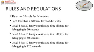
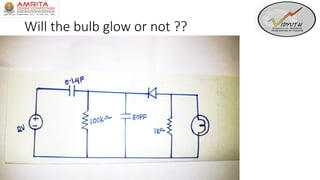
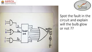
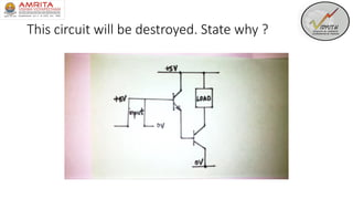
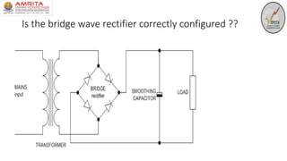
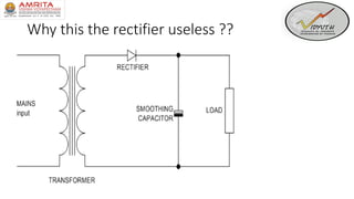
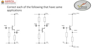
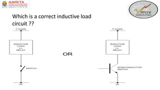
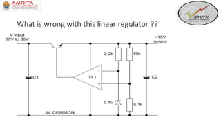
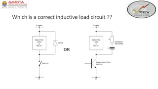
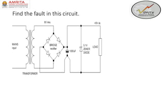
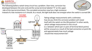
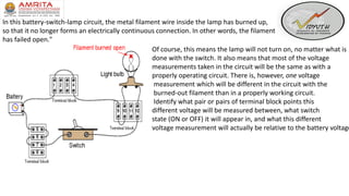
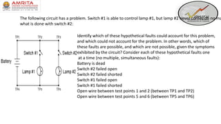
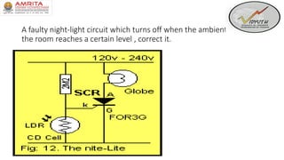
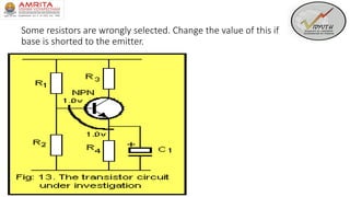
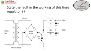
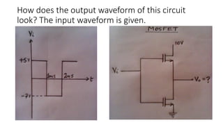
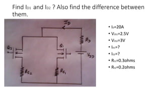
CIRCUIT
DEBUGGING
RULES AND REGULATIONS
•There are 3 levels for this contest
•Each level has a different level of difficulty
•Level 1 has 20 faulty circuits and time allotted for
debugging is 30 seconds
•Level 2 has 10 faulty circuits and time allotted for
debugging is 60 seconds
•Level 3 has 10 faulty circuits and time allotted for
debugging is 120 seconds
LEVEL 1 – GET SET GO…
Will the bulb glow or not ??
Why will the bulb not glow ??
Will the bulb glow or not state the
reasons
Spot the fault in the
circuit and explain
will the bulb glow
or not ??
Will the blub glow
?? State the reasons
Why will the bulb not glow ?
This circuit will be destroyed. State why ?
Will the bulb glow or not ?? State why
Will the blub glow ?? State the reasons
Why will the bulb not glow ??
Is the bridge wave rectifier correctly configured ??
Why this the rectifier useless ??
LEVEL 2- GET GOING…
•A technician builds a simple half-wave rectifier circuit for a project,
but is surprised to find that the diode keeps failing:
This comes as a surprise because the diode has a repetitive peak reverse voltage rating of 50 volts,
which the technician knows is greater than the peak voltage output by the step-down transformer.
However, the technician has overlooked something very important in this circuit design.
Explain what the problem is, and how to solve it.
Each transistor connection has a defect state it and suggest a correction
Correct each of the following that have same
applications
Which is a correct inductive load
circuit ??
What is wrong with this linear regulator ??
Which is a correct inductive load circuit ??
Find the fault in this circuit.
The following battery-switch-lamp circuit has a problem. Over time, corrosion has
developed between the wire end and the screw terminal labeled "4" on the upper
side of the top terminal block. This corroded connection now has a high resistance
instead of a low resistance as it should. As a result, the light bulb does not energize when the switch is turned ON:
Taking voltage measurements with a voltmeter,
how do you think this corrosion problem will reveal
itself with the switch on the ON position? In other words,
which voltage measurement in this circuit
(i.e. between which pair or pairs of terminal block points)
will be unusual as a result of the bad connection at point #4,
and approximately how much voltage
should that measurement be?
LEVEL 3- GET TO THE GOAL…
In this battery-switch-lamp circuit, the metal filament wire inside the lamp has burned up,
so that it no longer forms an electrically continuous connection. In other words, the filament
has failed open."
Of course, this means the lamp will not turn on, no matter what is
done with the switch. It also means that most of the voltage
measurements taken in the circuit will be the same as with a
properly operating circuit. There is, however, one voltage
measurement which will be different in the circuit with the
burned-out filament than in a properly working circuit.
Identify what pair or pairs of terminal block points this
different voltage will be measured between, what switch
state (ON or OFF) it will appear in, and what this different
voltage measurement will actually be relative to the battery voltage
This is a key hole light circuit. Find the fault of its construction to make it work.
The following circuit has a problem. Switch #1 is able to control lamp #1, but lamp #2 never comes on no ma
what is done with switch #2:
Identify which of these hypothetical faults could account for this problem,
and which could not account for the problem. In other words, which of
these faults are possible, and which are not possible, given the symptoms
exhibited by the circuit? Consider each of these hypothetical faults one
at a time (no multiple, simultaneous faults):
Battery is dead
Switch #2 failed open
Switch #2 failed shorted
Switch #1 failed open
Switch #1 failed shorted
Open wire between test points 1 and 2 (between TP1 and TP2)
Open wire between test points 5 and 6 (between TP5 and TP6)
A faulty night-light circuit which turns off when the ambient light in
the room reaches a certain level , correct it.
Suppose a technician measures the voltage output by an AC-DC power supply circuit:
The waveform shown by the oscilloscope is mostly DC, with just a little bit of
AC "ripple" voltage appearing as a ripple pattern on what would otherwise
be a straight, horizontal line.
This is quite normal for the output of an AC-DC power supply.
Suppose we wished to take a closer view of this "ripple" voltage.
We want to make the ripples more pronounced on the screen,
so that we may better discern their shape. Unfortunately, though, when
we decrease the number of volts per division on the "vertical"
control knob to magnify the vertical amplification of the oscilloscope,
the pattern completely disappears from the screen! Explain what the
problem is, and how we might correct it so as to be
able to magnify the ripple voltage waveform without
having it disappear off the oscilloscope screen.
Some resistors are wrongly selected. Change the value of this if
base is shorted to the emitter.
State the fault in the working of this linear
regulator ??
How does the output waveform of this circuit
look? The input waveform is given.
Find ID1 and ID2 ? Also find the difference between
them.
• ID=20A
• VDS1=2.5V
• VDS2=3V
• ID1=?
• ID2=?
• RS1=0.3ohms
• RS2=0.2ohms
For an n-channel MOSFET, if VGS =4.4V, VOV
=1V (overdrive voltage) and VGD =3V. What is
the region of operation in the output
characteristics. Justify your answer.
THANK YOU

CircuitDebugging

  • 1.
  • 2.
    RULES AND REGULATIONS •Thereare 3 levels for this contest •Each level has a different level of difficulty •Level 1 has 20 faulty circuits and time allotted for debugging is 30 seconds •Level 2 has 10 faulty circuits and time allotted for debugging is 60 seconds •Level 3 has 10 faulty circuits and time allotted for debugging is 120 seconds
  • 3.
    LEVEL 1 –GET SET GO…
  • 4.
    Will the bulbglow or not ??
  • 5.
    Why will thebulb not glow ??
  • 6.
    Will the bulbglow or not state the reasons
  • 7.
    Spot the faultin the circuit and explain will the bulb glow or not ??
  • 8.
    Will the blubglow ?? State the reasons
  • 9.
    Why will thebulb not glow ?
  • 10.
    This circuit willbe destroyed. State why ?
  • 11.
    Will the bulbglow or not ?? State why
  • 12.
    Will the blubglow ?? State the reasons
  • 13.
    Why will thebulb not glow ??
  • 14.
    Is the bridgewave rectifier correctly configured ??
  • 15.
    Why this therectifier useless ??
  • 16.
    LEVEL 2- GETGOING…
  • 17.
    •A technician buildsa simple half-wave rectifier circuit for a project, but is surprised to find that the diode keeps failing: This comes as a surprise because the diode has a repetitive peak reverse voltage rating of 50 volts, which the technician knows is greater than the peak voltage output by the step-down transformer. However, the technician has overlooked something very important in this circuit design. Explain what the problem is, and how to solve it.
  • 18.
    Each transistor connectionhas a defect state it and suggest a correction
  • 19.
    Correct each ofthe following that have same applications
  • 20.
    Which is acorrect inductive load circuit ??
  • 21.
    What is wrongwith this linear regulator ??
  • 22.
    Which is acorrect inductive load circuit ??
  • 23.
    Find the faultin this circuit.
  • 24.
    The following battery-switch-lampcircuit has a problem. Over time, corrosion has developed between the wire end and the screw terminal labeled "4" on the upper side of the top terminal block. This corroded connection now has a high resistance instead of a low resistance as it should. As a result, the light bulb does not energize when the switch is turned ON: Taking voltage measurements with a voltmeter, how do you think this corrosion problem will reveal itself with the switch on the ON position? In other words, which voltage measurement in this circuit (i.e. between which pair or pairs of terminal block points) will be unusual as a result of the bad connection at point #4, and approximately how much voltage should that measurement be?
  • 25.
    LEVEL 3- GETTO THE GOAL…
  • 26.
    In this battery-switch-lampcircuit, the metal filament wire inside the lamp has burned up, so that it no longer forms an electrically continuous connection. In other words, the filament has failed open." Of course, this means the lamp will not turn on, no matter what is done with the switch. It also means that most of the voltage measurements taken in the circuit will be the same as with a properly operating circuit. There is, however, one voltage measurement which will be different in the circuit with the burned-out filament than in a properly working circuit. Identify what pair or pairs of terminal block points this different voltage will be measured between, what switch state (ON or OFF) it will appear in, and what this different voltage measurement will actually be relative to the battery voltage
  • 27.
    This is akey hole light circuit. Find the fault of its construction to make it work.
  • 28.
    The following circuithas a problem. Switch #1 is able to control lamp #1, but lamp #2 never comes on no ma what is done with switch #2: Identify which of these hypothetical faults could account for this problem, and which could not account for the problem. In other words, which of these faults are possible, and which are not possible, given the symptoms exhibited by the circuit? Consider each of these hypothetical faults one at a time (no multiple, simultaneous faults): Battery is dead Switch #2 failed open Switch #2 failed shorted Switch #1 failed open Switch #1 failed shorted Open wire between test points 1 and 2 (between TP1 and TP2) Open wire between test points 5 and 6 (between TP5 and TP6)
  • 29.
    A faulty night-lightcircuit which turns off when the ambient light in the room reaches a certain level , correct it.
  • 30.
    Suppose a technicianmeasures the voltage output by an AC-DC power supply circuit: The waveform shown by the oscilloscope is mostly DC, with just a little bit of AC "ripple" voltage appearing as a ripple pattern on what would otherwise be a straight, horizontal line. This is quite normal for the output of an AC-DC power supply. Suppose we wished to take a closer view of this "ripple" voltage. We want to make the ripples more pronounced on the screen, so that we may better discern their shape. Unfortunately, though, when we decrease the number of volts per division on the "vertical" control knob to magnify the vertical amplification of the oscilloscope, the pattern completely disappears from the screen! Explain what the problem is, and how we might correct it so as to be able to magnify the ripple voltage waveform without having it disappear off the oscilloscope screen.
  • 31.
    Some resistors arewrongly selected. Change the value of this if base is shorted to the emitter.
  • 32.
    State the faultin the working of this linear regulator ??
  • 34.
    How does theoutput waveform of this circuit look? The input waveform is given.
  • 35.
    Find ID1 andID2 ? Also find the difference between them. • ID=20A • VDS1=2.5V • VDS2=3V • ID1=? • ID2=? • RS1=0.3ohms • RS2=0.2ohms
  • 36.
    For an n-channelMOSFET, if VGS =4.4V, VOV =1V (overdrive voltage) and VGD =3V. What is the region of operation in the output characteristics. Justify your answer.
  • 37.