

Recommended
Recommended
More Related Content
What's hot
What's hot (20)
Viewers also liked
Viewers also liked (20)
Similar to J1103017075
Similar to J1103017075 (20)
More from IOSR Journals
Recently uploaded
Recently uploaded (20)
J1103017075
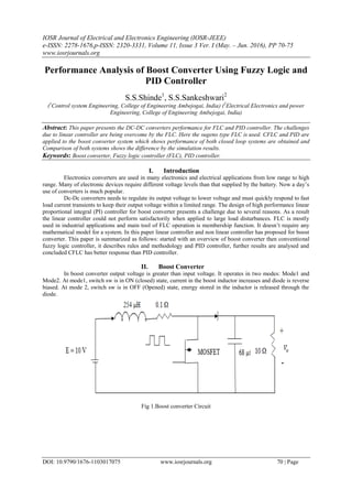
- 1. IOSR Journal of Electrical and Electronics Engineering (IOSR-JEEE) e-ISSN: 2278-1676,p-ISSN: 2320-3331, Volume 11, Issue 3 Ver. I (May. – Jun. 2016), PP 70-75 www.iosrjournals.org DOI: 10.9790/1676-1103017075 www.iosrjournals.org 70 | Page Performance Analysis of Boost Converter Using Fuzzy Logic and PID Controller S.S.Shinde1 , S.S.Sankeshwari2 (1 Control system Engineering, College of Engineering Ambejogai, India) (2 Electrical Electronics and power Engineering, College of Engineering Ambejogai, India) Abstract: This paper presents the DC-DC converters performance for FLC and PID controller. The challenges due to linear controller are being overcome by the FLC. Here the sugeno type FLC is used. CFLC and PID are applied to the boost converter system which shows performance of both closed loop systems are obtained and Comparison of both systems shows the difference by the simulation results. Keywords: Boost converter, Fuzzy logic controller (FLC), PID controller. I. Introduction Electronics converters are used in many electronics and electrical applications from low range to high range. Many of electronic devices require different voltage levels than that supplied by the battery. Now a day’s use of converters is much popular. Dc-Dc converters needs to regulate its output voltage to lower voltage and must quickly respond to fast load current transients to keep their output voltage within a limited range. The design of high performance linear proportional integral (PI) controller for boost converter presents a challenge due to several reasons. As a result the linear controller could not perform satisfactorily when applied to large load disturbances. FLC is mostly used in industrial applications and main tool of FLC operation is membership function. It doesn’t require any mathematical model for a system. In this paper linear controller and non linear controller has proposed for boost converter. This paper is summarized as follows: started with an overview of boost converter then conventional fuzzy logic controller, it describes rules and methodology and PID controller, further results are analysed and concluded CFLC has better response than PID controller. II. Boost Converter In boost converter output voltage is greater than input voltage. It operates in two modes: Mode1 and Mode2. At mode1, switch sw is in ON (closed) state, current in the boost inductor increases and diode is reverse biased. At mode 2, switch sw is in OFF (Opened) state, energy stored in the inductor is released through the diode. Fig 1.Boost converter Circuit
- 2. Performance Analysis of Boost Converter Using Fuzzy Logic And PID Controller DOI: 10.9790/1676-1103017075 www.iosrjournals.org 71 | Page TABLE I Values and parameters of boost converter used in simulation III. Methodology Fuzzy Logic Controller Fuzzy logic controller (FLC) has two controlled inputs error (e) and change of error (ce). The controlled parameter is the output voltage. Sugeno type FLC is used here. Membership functions for inputs and output is shown in figure 4, 5, 6.Rule table used is shown in below table Rule Table for error and change of error Above block diagram shows the fuzzy logic controller. There are three basic blocks of fuzzy logic controller. 1. Fuzzification block or fuzzifier. 2. Interference system. 3. Defuzzification block or defuzzifier. Fuzzification – It converts the input values i.e error signal into set of fuzzy variables. Fuzzy logic uses the linguistic variables but input is the numerical value. Hence, this conversion done by the fuzzification block. Interference system – It is segregated by the following. a) Rule base – It has the number of If-then rules. If side rule is called the antecedent and then side is called the consequence. b) Database – It consists of the all defined membership functions that are to be used by the rules. c) Reasoning mechanism - it process the rules. Defuzzification block – It performs the opposite function of fuzzifier.It transforms the fuzzy varia crisp ets.
- 3. Performance Analysis of Boost Converter Using Fuzzy Logic And PID Controller DOI: 10.9790/1676-1103017075 www.iosrjournals.org 72 | Page Fig 2. Block diagram of fuzzy logic controller Fig 4. Error Mf’s Fig 5. Change of error Mf’s Fig 6. Output Mf’s 1.1 PID Controller Proportional integrator derivative controller is used in feedback system. PID controller calculates an error value as the difference between measured process variable and a desired set point. If u(t) is the control signal sent to the system, y(t) is the measured output and r(t) is the desired output and tracking error e(t) = r(t) – y(t) then a PID controller has a general form, u t = Kp + KI e t dt + KD d dt e(t) (1)
- 4. Performance Analysis of Boost Converter Using Fuzzy Logic And PID Controller DOI: 10.9790/1676-1103017075 www.iosrjournals.org 73 | Page Fig 7. Block diagram of boost converter with PID controller IV. Simulation Results For MATLAB simulation boost converter model is used. Figure 8 shows output response of the converter when an input voltage is 10V load change of 5 Ω using FLC. From the response it is clear that after 20 msec output voltage is restored to its original value. Figure 9 shows output response for the same using PID controller, it is clear that sudden rise and restore below the original value. Fig 8. Output voltage of boost converter with FLC in load step change from 5 Ω Fig 9. Output voltage of boost converter with PID controller in load step change from 5Ω
- 5. Performance Analysis of Boost Converter Using Fuzzy Logic And PID Controller DOI: 10.9790/1676-1103017075 www.iosrjournals.org 74 | Page Fig 10. Output voltage of the boost converter with FLC for reference change from 15v to 20v for 10Ω Fig 11. Output voltage of the boost converter with PID controller for reference change from 15v to 20v for 10Ω Fig 12. Comparison of fuzzy and PID controller for boost converter
- 6. Performance Analysis of Boost Converter Using Fuzzy Logic And PID Controller DOI: 10.9790/1676-1103017075 www.iosrjournals.org 75 | Page V. Conclusion In this paper, CFLC and PID controller are used to regulate the boost converter output voltage. Simulation results of the systems shows the responses for the same load change 5 Ω, 10 Ω and their difference with the applied voltage 10 V. This suggests that FLC has stable output above an applied voltage and the boost converter boosted the output voltage on the other hand the PID controller has stable output below an applied voltage. References [1]. FazelTaeed, Zainalsalam, Member, IEEE and Shahrin M. Ayob member IEEE,”FPGA implementation of a single input fuzzy logic controller for boost converter with the absence of an external analog to digital converter”, IEEE transactions on industrial electronics,Vol. 59, No.2, February 2012. [2]. A. G. Perry, G. Feng, Y. Liu, and P. C. Sen, “A design method for PI-like fuzzy logic controllers for DC–DC converter, ”IEEE Trans. Ind. Electron., vol. 54, no. 5, pp. 2688–2696, Oct. 2007 [3]. Deepa. T VIT University, VandalurKelambakkam Road, Chennai “Performance comparison of boost converter by using fuzzy logic controller”, India Global journal of advanced research, Vol-2, Issue-3 PP. 629-637. [4]. Zainal Salam∗, FazelTaeed∗, and Shahrin Md. Ayob, “Design and Implementation of a Single Input Fuzzy Logic Controller for Boost Converters”, Journal of Power Electronics, Vol. 11, No. 4, July 2011. [5]. V. S. C. Raviraj and P. C. Sen, “Comparative study of proportional– integral, sliding mode, and fuzzy logic controllers for power converters,” IEEE Trans. Ind. Appl., vol. 33, no. 2, pp. 518–524, Mar./Apr. 1997. [6]. Fundamentals of Power Electronics By Robert W. Erickson, DraganMaksimovic [7]. M. H. Rashid, Power Electronics Handbook: Devices, Circuits, and Applications. San Diego, CA: Academic, 2001.