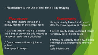
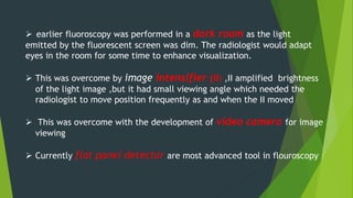
FLUOROSCOPY
PRESENTER: DR SOHAIL
GUIDED BY DR CHANDIPRIYA
FROM PAST TO PRESENT
Fluoroscopy is the use of real time x-ray imaging
Fluoroscopy
ƒ Real time imaging viewed on a
display monitor in the clinical room
ƒ Matrix is smaller (512 x 512 pixels)
and 8 bits of grey scale only needed as
temporal resolution is prioritized
ƒ Can acquire continuous (cine) or
pulsed
fluorographic images
Fluorography
ƒ Images usually formed and viewed
after the x-ray exposure is completd
ƒ Better quality images acquired than in
floroscopy but at higher doses
ƒ MATRIX is typically 1024 x 1024 pixels
with each pixel representing 10 bits of
grey
scale information
 earlier fluoroscopy was performed in a dark room as the light
emitted by the fluorescent screen was dim. The radiologist would adapt
eyes in the room for some time to enhance visualization.
 This was overcome by image intensifier (II) ,II amplified brightness
of the light image ,but it had small viewing angle which needed the
radiologist to move position frequently as and when the II moved
 This was overcome with the development of video camera for image
viewing
 Currently flat panel detector are most advanced tool in flouroscopy
Generator:
.high frequency generator with faster switching for easy exposure
reproducibility
Tube:
. 2 focal spots ,small is used for fluoroscopy
. High heat capacity (rotating anode,cooling fans,grid exposures
Filters:
.cu > al (better absorptn)
.equalization ficontrolledlter: lead acrylic ,to reduce glare near edges
grids:
.lower ratio grids
.removable grids causing air gap
exposure:
.lower exposure rate( lower current) than radiography ,but overall higher
xposure bcz of duration
Flouroscopy vs radiography setup
 II system is characterised by the ability to convert the input light into a
much higher output (gain or intensification)
Image intensifier (II)
Internal construction of an II x-ray tube:
1. Input screen
2. Electron-optics
3. Output stage
These parts are within a vaccum glass tube from external magnetic
or electric feilds
II input window
ƒ Convex metal shield that covers the input
face of the II Usually made of aluminium or titanium foil (low Z metal) to allow
x-ray beam to enter with minimum attenuation
ƒ protection for sensitive input components of the tube and maintains
the vacuum
Input phosphor
ƒ Layer of sodium activated caesium iodide (CsI:Na) for good x-ray absorption
efficiency (70-90%)Channelled into tiny needle-like crystals
(5µm in diameter) with fibreoptic-like
characteristics
ƒ Deposited on a thin aluminium substrate. CsI:Na usually 400-500µm thick
ƒ Each x-ray photon produces ~3000 light
photons in the blue spectrum
Photocathode
ƒ Fluorescent emission from phosphor then absorbed in a light-
activated photocathode comprising a very thin layer of antimony
caesium (SbCs3) alloy that has a
spectral sensitivity well matched to the blue light emission of
CsI:Na
ƒ Absorption of the fluorescent light photons releases a pattern of
electrons in the body of the II tube
ƒ Approximately 200 electrons released per absorbed x-ray photon
2) II electron optics
The input screen is maintained at a negative voltage with respect to the
anode (output screen) with potential difference of 25 kV. This means the
electrons produced are accelerated across the II tube and carefully focused on
the output screen.
 The output screen is 1/10 the diameter of the input
screen and, therefore, a minified and inverted
image is produced.
Focusing electrodes are metal rings within the tube that are held at positive
voltages with respect to the photocathode.
This constrains the electrons in the tube to travel along paths
, such that the pattern of electron intensities
falling on the screen are an exact (but minified) replica of the pattern
intensities on the input screen
II Output screen
Thin layer of silver-activated zinc cadmium
sulphide (ZnCdS:Ag) crystals deposited on the inner surface of the
output window that
convert the electrons into light photons.
The output image is intensified significantly by the
acceleration of the electrons and the minification of the image that
occurs in the II tube.
The screen is normally 25-35 mm in diameter
and a few micrometres thick.
Compare to input screen, ouput screen is smaller and thin.
Summary
1. X-ray photons enter tube through aluminium or titanium
window
2. Hit input phosphor layer of sodium activated caesium iodide
and release light photons
3. Light photons detected by
photocathode(ANTIMONYCAESIUM) that then release electrons
into the tube
4. Electrons accelerated and focused onto
the output screen (silver-activated zinc cadmium sulphide
crystals) as a minified and inverted image
5. Light photons released that then leave
through the output window
XRAY PHOTONS – LIGHT PHOTONS- PHOTOELECTRONS –LIGHT PHOTONS
PROPRTIES OF II
BRIGHTNESS GAIN:
. The degree to which an image is intensified (or amplified) is given by
the brightness gain (G brightness)
. which is ratio of brightness of output screen to input screen
.G (brightness) : minification gain # flux gain
.G(minification) = (D input / Doutput) 2
Where: Dinput = diameter of the input screen
Doutput = diameter of the output screen*
ƒ Flux -
.Higher voltage difference applied
across II tube = more flux gain
 limitation:gain is difficult to measure,hence we use
intensification factor
Intensification factor
Ratio of . brightness of output phosphor (luminance in cdm-2)
.dose rate at input surface (exposure rate microgray per
sec)
Magnification mode:
.input screen is collimated to lesser FOV
.physical size of both screens remain same
.reduction in minification gain ,hence less bright image
.which is compensated by increased dose
.resolution increases
Artefacts of ii
Vignetting : centre of image is brighter
Pin cushion distortion :magnification of peripheries
both of these occur dur to convex shape of input screen and
unequal distance travelled by electrons
S shaped distortion: due to defocusing of electrons
clinically relevant in case of fractures
lag:delay betn 2 successive images
reduces temporal resolution
Veiling glare of flare:due to scaterring of electrons
Veling glare
Optical distribution and video system
Collimator lens:beam is collimated and
parallel
Beam splitting mirror:splits beam into
two,one reaches video camera for
viewing and the other to film camera for
recording
AEC mirror: transmit light beam to AEC
sensor
Video system
1.Vaccum tube sensor
Named based on photoconductor used
Vidicon:antimony trisulfide
Plumbicon:lead oxide
saticon:selenium,arsenic and tellurium
Hole density in photoconductor layer which is proportional to light intensity is measured by electron
beam scanner resulting in voltage signal as the output
2.CCD cameras
TARGET MATERIAL :THALLIM DOPED
CAESIUM IODIDE
Generates electron hole
pairs depending on light
intensity and negative
charge is read out
Advantages of ccd cameras
.better dynamic range( 12 bit depth )
.better contrast resolution hence lower dose
.linear response useful in substraction imaging
.less lag periof,hence improved temporal
resolution
.consume less electricity
Tv monitor
VOLTAGE SIGNAL is read from
crt or ccd by tv monitor
this signal is scanned in both
horizontal and vertical direction
Vertical resolution depends on
number of vertical lines
Horizontal resolution depends
on frequency bandwidth
flat Panel Detector:
 Flat panel detectors utilise the same technology as
digital radiography in that there is a flat panel of
detectors that provide a direct electronic readout
instead of requiring the conversion of analogue to
digital as is seen in the IITV.
 Similar to digital radiography dynamic FP detectors
can be direct or indirect. However, they are more
commonly indirect with a CsI:Tl x-ray scintillator
layer which is superimposed onto an a-Si high
resolution active matrix.
Benefits
ƒ Smaller equipment
ƒ Video signal emerges in digital form, reducing electronic noise
ƒ Square or rectangular field (unlike circular field in IITV) = better
coverage in the corners
ƒ Better temporal resolution with matrix
size of 2048 x 2048 pixels
ƒ Greyscale of 12 or 14 bits per pixel
ƒ produces better quality images than IITV
ƒ Fewer artefacts such as geometrical distortion, vignetting or contrast
loss
ƒ Detective quantum efficiency 10-20%
better than IITV so can afford to reduce
patient dose
ƒZoom option available (but doesn’t increase spatial resolution as it does
in IITV)
limitations
 Increased cost and difficulty in manufacturing
 Lower spatial resolution than ii(but effective
resolution is higher),resolution can be improvd by
lowering size of DEL
 Bining: to reduce noise ,data from four DEL is
merged into sigle which reduces spatial resolution
 ghosting: due to persistence of previous image in
scintillation crystal causes blurring while scanning
moving structures
1.Spot film devices use conventional screen-film cassettes for
documenting images. The cassetteis parked out of the way during routine
fluoroscopy and during acquisition moves into the field.
The limitations include inability to use larger sized cassettes and delay that
occurs during acquisition for the cassette to move into the field
2.Automatic film changers are mounted on II and include a supply
magazine containing unexposedfilms (up to 30 films), pair of high speed screens, a
receiving magazine which receives exposed filmsand a motor system for moving
films (usually at a maximum rate of 4 films/second)
. The disadvantages include use of only single film size, delay in documentation,
motion blurring, film fogging and jamming and missed exposures
Recording of images:
Light image recoders
Photofluorography allows rapid filming up to an extent of 12 films per second.
The photospotcamera is side mounted and obtains image transmitted from beam
splitting mirror. The films used areroll films which are typically 105 mm wide. Thus
the images here are minified.
. The advantagesinclude reduced dose, cheaper films, less storage space and less
delay in exposure.
The limitations include poorer resolution and smaller sized images.
Digital fluorography uses CCD cameras or FPD where the images are digitally
stored.
This limitation in resolution is surmounted by the ability of postprocessing of the
images.
Other benefits include option of film less system, immediate viewing of images
without delay and linear response which obviates overor under exposure
Cine fluorography: using a cine camera,directly records from output
phosphor is regularly used for recording of movement of contrast in the
vessels.
The frame rate of exposure can be adjusted as needed.
Grid controlled tubes are often used to turn X-ray exposure on and off quickly
in synchrony with the camera shutter.
Recording motions:
Tape and disc recorders:
laser optical discs are prefferd over magnetic disc an tapes
Digital storage of videos of movements are now done with availability
of digital flouroscopy
Configuration of fluoroscopic equipment
Standard radiography/fluoroscopy (R/F):. Under table x-ray tube wit
h an overcouch II system
. Table can be tilted and rotated
. Radiologist stands beside patient to operate system
Adv : reduced scatter radiation
Remote control R/F:
. X-ray tube mounted over the bed and II system underneath
. Higher scattered dose so radiologist has to stand behind screen to operate
system via remote control
Adv : tube angulation
same tube for radiography
remote control access
limitation: increased scatter
Fixed C-arm:
II x-ray tube and II system attached to a C-structure that allows it to be rotated around
and moved up and down patient as required
Can be ceiling or floor mounted
ƒ
Mobile C-arm:
System that can be transported on wheels to where it is needed e.g. theatres
BIPLANAR C ARM FLOUROSCOPIC EQUIPMENT
CONTIN0US VS PULSED MODES OF FLOROSCOPY
CONTINOUS MODE: images acquired at 30 fps
Pulsed mode : image betn 2.5 to 30 fps
. This is achieved by 2 methods
1.Generator controlled: current is applied in pulses
2.Grid controlled :neg charged grid is placed between cathode and anode
Image quality in flouroscopy
Automatic brightness control:
automatic dose rate control
. The purpose of the ABC is to maintain constant viewing condition independent of examination
ampling the video signal or by measuring the II
light output with a photo-sensor by feedback
.the need to alter the mA or kV is determined by either
electronically or by s
1.Kvp variability: ma constant
2.Ma variability: kvp constant,slower response
3.Both ma and kv variability
4.Pulse width variability:lenghth of exposure is controlled
kvp and ma levels are constant ,hence best kvp and mas values can
be chosen for an examination
. In AGC, TV camera electronically increases the brightness of the image on the
monitor when it is dim and noisy.
. only maintains brightness and does not change radiation exposure.
. The lag time for AGC is in terms of millisecond
Automatic gain control:
Digital image processing
grayscale processing involves adjustment of brightness and contrast of the image
.This is done by adjusting two values: window level and window width.
. Window level is the central value of the grayscale range of the image and window
width is the range displayed on either sides of window level.
. The level and width are adjusted depending on the region of interest with darker
objects needing lower window level, brighter objects higher window level and soft
tissues needing higher window width values
Last image hold (LIH) The last image/frame of cine
fluoroscopy at which imaging stops, is captured and continuously displayed on the monitor even
after switching-off the fluoroscopy. This image can be transferred to reference monitor and is used
for guidance without additional radiation to the patient and medical staff. This is applicable for static
objects.
For areas which are in motion (e.g. cardiac imaging) fluoroscopy loop can be captured and
made available for review when needed. Here, the last 150 to 300 frames or about 10 seconds of
fluoroscopy can be saved.
This reduces the additional need of radiation
temporal filtering
ƒThis is used to decrease the level of noise
ƒThe current frame is averaged with a set of the preceding frames. This creates
a digitally generated lag to smooth the noise fluctuations.
Spatial filtering:
similar to edge enhnancement
spatial resolution is improved
Minimising patient dose
ƒ Setup of equipment
.Tight collimation of x-ray beam
.Appropriate x-ray beam spectral filter to minimise patient skin dose rate
. Increase distance between patient
and x-ray source
. Minimise gap between patient and II
entrance
Remove anti-scatter grid if possible
ƒ
Imaging procedure
.Avoid constantly imaging at same projection angle
.ABC mode with lowest dose rate possible for diagnostic images
. Pulsed fluoroscopy with minimum acceptable pulse rate if possible
.Avoid use of II zoom
ƒ
Digital processes;
Last-image-hold
temporal averaging

flouroscopy.pptx

  • 1.
    FLUOROSCOPY PRESENTER: DR SOHAIL GUIDEDBY DR CHANDIPRIYA FROM PAST TO PRESENT
  • 2.
    Fluoroscopy is theuse of real time x-ray imaging Fluoroscopy ƒ Real time imaging viewed on a display monitor in the clinical room ƒ Matrix is smaller (512 x 512 pixels) and 8 bits of grey scale only needed as temporal resolution is prioritized ƒ Can acquire continuous (cine) or pulsed fluorographic images Fluorography ƒ Images usually formed and viewed after the x-ray exposure is completd ƒ Better quality images acquired than in floroscopy but at higher doses ƒ MATRIX is typically 1024 x 1024 pixels with each pixel representing 10 bits of grey scale information
  • 3.
     earlier fluoroscopywas performed in a dark room as the light emitted by the fluorescent screen was dim. The radiologist would adapt eyes in the room for some time to enhance visualization.  This was overcome by image intensifier (II) ,II amplified brightness of the light image ,but it had small viewing angle which needed the radiologist to move position frequently as and when the II moved  This was overcome with the development of video camera for image viewing  Currently flat panel detector are most advanced tool in flouroscopy
  • 6.
    Generator: .high frequency generatorwith faster switching for easy exposure reproducibility Tube: . 2 focal spots ,small is used for fluoroscopy . High heat capacity (rotating anode,cooling fans,grid exposures Filters: .cu > al (better absorptn) .equalization ficontrolledlter: lead acrylic ,to reduce glare near edges grids: .lower ratio grids .removable grids causing air gap exposure: .lower exposure rate( lower current) than radiography ,but overall higher xposure bcz of duration Flouroscopy vs radiography setup
  • 7.
     II systemis characterised by the ability to convert the input light into a much higher output (gain or intensification) Image intensifier (II) Internal construction of an II x-ray tube: 1. Input screen 2. Electron-optics 3. Output stage These parts are within a vaccum glass tube from external magnetic or electric feilds
  • 10.
    II input window ƒConvex metal shield that covers the input face of the II Usually made of aluminium or titanium foil (low Z metal) to allow x-ray beam to enter with minimum attenuation ƒ protection for sensitive input components of the tube and maintains the vacuum Input phosphor ƒ Layer of sodium activated caesium iodide (CsI:Na) for good x-ray absorption efficiency (70-90%)Channelled into tiny needle-like crystals (5µm in diameter) with fibreoptic-like characteristics ƒ Deposited on a thin aluminium substrate. CsI:Na usually 400-500µm thick ƒ Each x-ray photon produces ~3000 light photons in the blue spectrum
  • 11.
    Photocathode ƒ Fluorescent emissionfrom phosphor then absorbed in a light- activated photocathode comprising a very thin layer of antimony caesium (SbCs3) alloy that has a spectral sensitivity well matched to the blue light emission of CsI:Na ƒ Absorption of the fluorescent light photons releases a pattern of electrons in the body of the II tube ƒ Approximately 200 electrons released per absorbed x-ray photon
  • 12.
    2) II electronoptics The input screen is maintained at a negative voltage with respect to the anode (output screen) with potential difference of 25 kV. This means the electrons produced are accelerated across the II tube and carefully focused on the output screen.  The output screen is 1/10 the diameter of the input screen and, therefore, a minified and inverted image is produced. Focusing electrodes are metal rings within the tube that are held at positive voltages with respect to the photocathode. This constrains the electrons in the tube to travel along paths , such that the pattern of electron intensities falling on the screen are an exact (but minified) replica of the pattern intensities on the input screen
  • 13.
    II Output screen Thinlayer of silver-activated zinc cadmium sulphide (ZnCdS:Ag) crystals deposited on the inner surface of the output window that convert the electrons into light photons. The output image is intensified significantly by the acceleration of the electrons and the minification of the image that occurs in the II tube. The screen is normally 25-35 mm in diameter and a few micrometres thick. Compare to input screen, ouput screen is smaller and thin.
  • 14.
    Summary 1. X-ray photonsenter tube through aluminium or titanium window 2. Hit input phosphor layer of sodium activated caesium iodide and release light photons 3. Light photons detected by photocathode(ANTIMONYCAESIUM) that then release electrons into the tube 4. Electrons accelerated and focused onto the output screen (silver-activated zinc cadmium sulphide crystals) as a minified and inverted image 5. Light photons released that then leave through the output window XRAY PHOTONS – LIGHT PHOTONS- PHOTOELECTRONS –LIGHT PHOTONS
  • 15.
    PROPRTIES OF II BRIGHTNESSGAIN: . The degree to which an image is intensified (or amplified) is given by the brightness gain (G brightness) . which is ratio of brightness of output screen to input screen .G (brightness) : minification gain # flux gain .G(minification) = (D input / Doutput) 2 Where: Dinput = diameter of the input screen Doutput = diameter of the output screen* ƒ Flux - .Higher voltage difference applied across II tube = more flux gain  limitation:gain is difficult to measure,hence we use intensification factor
  • 16.
    Intensification factor Ratio of. brightness of output phosphor (luminance in cdm-2) .dose rate at input surface (exposure rate microgray per sec)
  • 17.
    Magnification mode: .input screenis collimated to lesser FOV .physical size of both screens remain same .reduction in minification gain ,hence less bright image .which is compensated by increased dose .resolution increases
  • 18.
    Artefacts of ii Vignetting: centre of image is brighter Pin cushion distortion :magnification of peripheries both of these occur dur to convex shape of input screen and unequal distance travelled by electrons S shaped distortion: due to defocusing of electrons clinically relevant in case of fractures lag:delay betn 2 successive images reduces temporal resolution Veiling glare of flare:due to scaterring of electrons
  • 20.
  • 21.
    Optical distribution andvideo system Collimator lens:beam is collimated and parallel Beam splitting mirror:splits beam into two,one reaches video camera for viewing and the other to film camera for recording AEC mirror: transmit light beam to AEC sensor
  • 22.
    Video system 1.Vaccum tubesensor Named based on photoconductor used Vidicon:antimony trisulfide Plumbicon:lead oxide saticon:selenium,arsenic and tellurium
  • 23.
    Hole density inphotoconductor layer which is proportional to light intensity is measured by electron beam scanner resulting in voltage signal as the output
  • 24.
    2.CCD cameras TARGET MATERIAL:THALLIM DOPED CAESIUM IODIDE Generates electron hole pairs depending on light intensity and negative charge is read out
  • 25.
    Advantages of ccdcameras .better dynamic range( 12 bit depth ) .better contrast resolution hence lower dose .linear response useful in substraction imaging .less lag periof,hence improved temporal resolution .consume less electricity
  • 26.
    Tv monitor VOLTAGE SIGNALis read from crt or ccd by tv monitor this signal is scanned in both horizontal and vertical direction Vertical resolution depends on number of vertical lines Horizontal resolution depends on frequency bandwidth
  • 27.
    flat Panel Detector: Flat panel detectors utilise the same technology as digital radiography in that there is a flat panel of detectors that provide a direct electronic readout instead of requiring the conversion of analogue to digital as is seen in the IITV.  Similar to digital radiography dynamic FP detectors can be direct or indirect. However, they are more commonly indirect with a CsI:Tl x-ray scintillator layer which is superimposed onto an a-Si high resolution active matrix.
  • 29.
    Benefits ƒ Smaller equipment ƒVideo signal emerges in digital form, reducing electronic noise ƒ Square or rectangular field (unlike circular field in IITV) = better coverage in the corners ƒ Better temporal resolution with matrix size of 2048 x 2048 pixels ƒ Greyscale of 12 or 14 bits per pixel ƒ produces better quality images than IITV ƒ Fewer artefacts such as geometrical distortion, vignetting or contrast loss ƒ Detective quantum efficiency 10-20% better than IITV so can afford to reduce patient dose ƒZoom option available (but doesn’t increase spatial resolution as it does in IITV)
  • 30.
    limitations  Increased costand difficulty in manufacturing  Lower spatial resolution than ii(but effective resolution is higher),resolution can be improvd by lowering size of DEL  Bining: to reduce noise ,data from four DEL is merged into sigle which reduces spatial resolution  ghosting: due to persistence of previous image in scintillation crystal causes blurring while scanning moving structures
  • 31.
    1.Spot film devicesuse conventional screen-film cassettes for documenting images. The cassetteis parked out of the way during routine fluoroscopy and during acquisition moves into the field. The limitations include inability to use larger sized cassettes and delay that occurs during acquisition for the cassette to move into the field 2.Automatic film changers are mounted on II and include a supply magazine containing unexposedfilms (up to 30 films), pair of high speed screens, a receiving magazine which receives exposed filmsand a motor system for moving films (usually at a maximum rate of 4 films/second) . The disadvantages include use of only single film size, delay in documentation, motion blurring, film fogging and jamming and missed exposures Recording of images: Light image recoders
  • 32.
    Photofluorography allows rapidfilming up to an extent of 12 films per second. The photospotcamera is side mounted and obtains image transmitted from beam splitting mirror. The films used areroll films which are typically 105 mm wide. Thus the images here are minified. . The advantagesinclude reduced dose, cheaper films, less storage space and less delay in exposure. The limitations include poorer resolution and smaller sized images. Digital fluorography uses CCD cameras or FPD where the images are digitally stored. This limitation in resolution is surmounted by the ability of postprocessing of the images. Other benefits include option of film less system, immediate viewing of images without delay and linear response which obviates overor under exposure
  • 33.
    Cine fluorography: usinga cine camera,directly records from output phosphor is regularly used for recording of movement of contrast in the vessels. The frame rate of exposure can be adjusted as needed. Grid controlled tubes are often used to turn X-ray exposure on and off quickly in synchrony with the camera shutter. Recording motions: Tape and disc recorders: laser optical discs are prefferd over magnetic disc an tapes Digital storage of videos of movements are now done with availability of digital flouroscopy
  • 34.
    Configuration of fluoroscopicequipment Standard radiography/fluoroscopy (R/F):. Under table x-ray tube wit h an overcouch II system . Table can be tilted and rotated . Radiologist stands beside patient to operate system Adv : reduced scatter radiation
  • 35.
    Remote control R/F: .X-ray tube mounted over the bed and II system underneath . Higher scattered dose so radiologist has to stand behind screen to operate system via remote control Adv : tube angulation same tube for radiography remote control access limitation: increased scatter
  • 36.
    Fixed C-arm: II x-raytube and II system attached to a C-structure that allows it to be rotated around and moved up and down patient as required Can be ceiling or floor mounted ƒ Mobile C-arm: System that can be transported on wheels to where it is needed e.g. theatres
  • 37.
    BIPLANAR C ARMFLOUROSCOPIC EQUIPMENT
  • 38.
    CONTIN0US VS PULSEDMODES OF FLOROSCOPY CONTINOUS MODE: images acquired at 30 fps Pulsed mode : image betn 2.5 to 30 fps . This is achieved by 2 methods 1.Generator controlled: current is applied in pulses 2.Grid controlled :neg charged grid is placed between cathode and anode
  • 41.
    Image quality inflouroscopy Automatic brightness control: automatic dose rate control . The purpose of the ABC is to maintain constant viewing condition independent of examination ampling the video signal or by measuring the II light output with a photo-sensor by feedback .the need to alter the mA or kV is determined by either electronically or by s 1.Kvp variability: ma constant 2.Ma variability: kvp constant,slower response 3.Both ma and kv variability
  • 43.
    4.Pulse width variability:lenghthof exposure is controlled kvp and ma levels are constant ,hence best kvp and mas values can be chosen for an examination . In AGC, TV camera electronically increases the brightness of the image on the monitor when it is dim and noisy. . only maintains brightness and does not change radiation exposure. . The lag time for AGC is in terms of millisecond Automatic gain control:
  • 44.
    Digital image processing grayscaleprocessing involves adjustment of brightness and contrast of the image .This is done by adjusting two values: window level and window width. . Window level is the central value of the grayscale range of the image and window width is the range displayed on either sides of window level. . The level and width are adjusted depending on the region of interest with darker objects needing lower window level, brighter objects higher window level and soft tissues needing higher window width values
  • 45.
    Last image hold(LIH) The last image/frame of cine fluoroscopy at which imaging stops, is captured and continuously displayed on the monitor even after switching-off the fluoroscopy. This image can be transferred to reference monitor and is used for guidance without additional radiation to the patient and medical staff. This is applicable for static objects. For areas which are in motion (e.g. cardiac imaging) fluoroscopy loop can be captured and made available for review when needed. Here, the last 150 to 300 frames or about 10 seconds of fluoroscopy can be saved. This reduces the additional need of radiation temporal filtering ƒThis is used to decrease the level of noise ƒThe current frame is averaged with a set of the preceding frames. This creates a digitally generated lag to smooth the noise fluctuations. Spatial filtering: similar to edge enhnancement spatial resolution is improved
  • 46.
    Minimising patient dose ƒSetup of equipment .Tight collimation of x-ray beam .Appropriate x-ray beam spectral filter to minimise patient skin dose rate . Increase distance between patient and x-ray source . Minimise gap between patient and II entrance Remove anti-scatter grid if possible ƒ Imaging procedure .Avoid constantly imaging at same projection angle .ABC mode with lowest dose rate possible for diagnostic images . Pulsed fluoroscopy with minimum acceptable pulse rate if possible .Avoid use of II zoom ƒ Digital processes; Last-image-hold temporal averaging