Downloaded 107 times


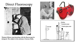
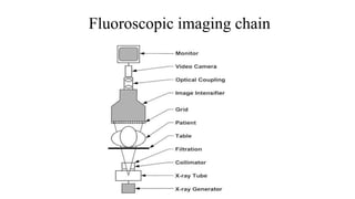
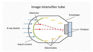
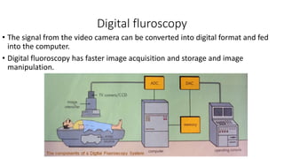


1) Fluoroscopy uses pulsed or continuous X-rays and a video camera system to generate real-time moving images of the internal structures of the body. 2) Early fluoroscopy used image intensifiers to convert X-rays to visible light images, while modern digital fluoroscopy uses flat panel detectors and pulse-progressive fluoroscopy to acquire images. 3) Automatic brightness control and magnification allow fluoroscopy units to maintain image brightness and zoom in on areas of interest, while advances in digital technology provide faster imaging, image storage, and lower radiation doses.


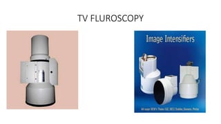
![Portable and mobile radiographic equipments [Autosaved].pptx](https://cdn.slidesharecdn.com/ss_thumbnails/portableandmobileradiographicequipmentsautosaved-230729155829-aadaaabd-thumbnail.jpg?width=640&height=640&fit=bounds)


