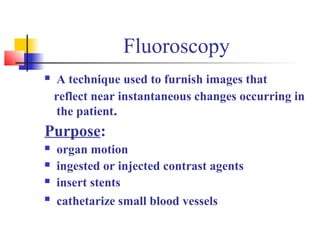
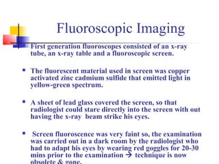
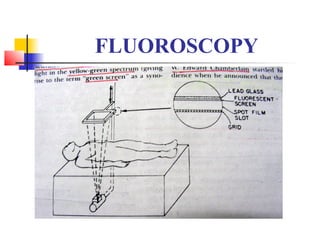
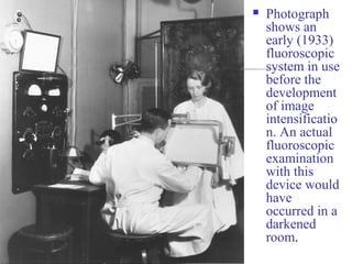
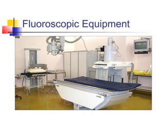
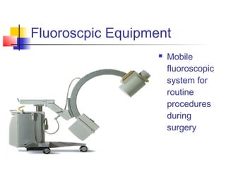
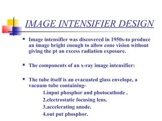
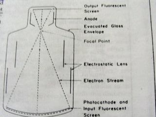
Fluroscopic Imaging 
Image Intensifier Design 
Vidicon & CCD Camera 
BY- Ruta Satoskar.
Fluoroscopy 
 A technique used to furnish images that 
reflect near instantaneous changes occurring in 
the patient. 
Purpose: 
 organ motion 
 ingested or injected contrast agents 
 insert stents 
 cathetarize small blood vessels
Fluoroscopic Imaging 
 First generation fluoroscopes consisted of an x-ray 
tube, an x-ray table and a fluoroscopic screen. 
 The fluorescent material used in screen was copper 
activated zinc cadmium sulfide that emitted light in 
yellow-green spectrum. 
 A sheet of lead glass covered the screen, so that 
radiologist could stare directly into the screen with out 
having the x-ray beam strike his eyes. 
 Screen fluoroscence was very faint so, the examination 
was carried out in a dark room by the radiologist who 
had to adapt his eyes by wearing red goggles for 20-30 
mins prior to the examination  technique is now 
obsolete & gone.
FLUOROSCOPY
 Photograph 
shows an 
early (1933) 
fluoroscopic 
system in use 
before the 
development 
of image 
intensificatio 
n. An actual 
fluoroscopic 
examination 
with this 
device would 
have 
occurred in a 
darkened 
room.
Fluoroscopic Equipment
Fluoroscpic Equipment 
 Mobile 
fluoroscopic 
system for 
routine 
procedures 
during 
surgery
IMAGE INTENSIFIER DESIGN 
 Image intensifier was discovered in 1950s-to produce 
an image bright enough to allow cone vision without 
giving the pt an excess radiation exposure. 
 The components of an x-ray image intensifier: 
 The tube itself is an evacuated glass envelope, a 
vacuum tube containing- 
1.input phosphor and photocathode . 
2.electrostatic focusing lens. 
3.accelerating anode. 
4.out put phosphor.
Input Phosphor & Photocathode 
 The input fluorescent screen in image intensifiers is 
cesium iodide (CsI). (older intensifier- silver activated 
zinc cadmium sulfide). 
 CsI is deposited on a thin aluminum substrate by a 
process called “vapor deposition”.  an interesting & 
useful characteristic of CsI is that during the deposition 
process the crystals of CsI grow in tiny needles 
perpendicular to the substrate.  There by reducing 
scattering.
Photocathode 
 The photo cathode is a photoemissive metal (commonly 
a combination of antimony & cesium compounds). 
 When the light from the fluorescent screen strikes the 
photo cathode, photo electrons are emitted in numbers 
proportional to the brightness of the screen. 
 The photoelectrons thus produced has to be moved to 
the other end of the image intensifier. This can be done 
using an electrostatic focusing lens and an accelerating 
anode.
Electrostatic Focusing Lens 
 The lens is made up of a series positively charged 
electrodes that are usually plated on to the inside 
surface of the glass envelope. 
 These electrodes focus the electron beam as it flows 
from the photocathode toward the output phosphor. 
 Electron focusing inverts & reverses the image which is 
called “point inversion” because all the electrons pass 
through a common focal point on their way to output 
phosphor. 
 The image on the output phosphor is reduced in size 
,which is one of the principle reasons why it is brighter.
AACCCCEELLEERRAATTIINNGG AANNOODDEE :: 
•The anode is located in the neck of the image tube. 
•Its function is to accelerate electrons emitted from the 
photocathode towards the output screen. 
•The anode has a +ve potential of 25 to 35 kv relative to the 
photocathode, so it accelerates electrons to a tremendous 
velocity. 
OOUUTTPPUUTT PPHHOOSSPPHHOORR:: 
•The output fluorescent screen of image intensifiers is silver 
activated zn-cd sulfide. 
•Crystal size and layer thickness are reduced to maintain 
resolution in the minified image.
Output Phosphor contd. 
 A thin layer of aluminum is plated onto the fluorescent 
screen prevent light from moving retrograde 
through the tube & activating the photocathode. 
 The glass tube of the image intensifier is abt 2 to 4mm 
thick & is enclosed in a lead lined metal container 
protects the operator from stray radiation. 
 The output phosphor image is viewed either directly 
through a series of lenses and mirrors or indirectly 
through closed circuit TV.
Fluroscopic imaging ppt

Fluroscopic imaging ppt

  • 1.
    Fluroscopic Imaging ImageIntensifier Design Vidicon & CCD Camera BY- Ruta Satoskar.
  • 2.
    Fluoroscopy  Atechnique used to furnish images that reflect near instantaneous changes occurring in the patient. Purpose:  organ motion  ingested or injected contrast agents  insert stents  cathetarize small blood vessels
  • 3.
    Fluoroscopic Imaging First generation fluoroscopes consisted of an x-ray tube, an x-ray table and a fluoroscopic screen.  The fluorescent material used in screen was copper activated zinc cadmium sulfide that emitted light in yellow-green spectrum.  A sheet of lead glass covered the screen, so that radiologist could stare directly into the screen with out having the x-ray beam strike his eyes.  Screen fluoroscence was very faint so, the examination was carried out in a dark room by the radiologist who had to adapt his eyes by wearing red goggles for 20-30 mins prior to the examination  technique is now obsolete & gone.
  • 4.
  • 5.
     Photograph showsan early (1933) fluoroscopic system in use before the development of image intensificatio n. An actual fluoroscopic examination with this device would have occurred in a darkened room.
  • 6.
  • 7.
    Fluoroscpic Equipment Mobile fluoroscopic system for routine procedures during surgery
  • 8.
    IMAGE INTENSIFIER DESIGN  Image intensifier was discovered in 1950s-to produce an image bright enough to allow cone vision without giving the pt an excess radiation exposure.  The components of an x-ray image intensifier:  The tube itself is an evacuated glass envelope, a vacuum tube containing- 1.input phosphor and photocathode . 2.electrostatic focusing lens. 3.accelerating anode. 4.out put phosphor.
  • 10.
    Input Phosphor &Photocathode  The input fluorescent screen in image intensifiers is cesium iodide (CsI). (older intensifier- silver activated zinc cadmium sulfide).  CsI is deposited on a thin aluminum substrate by a process called “vapor deposition”.  an interesting & useful characteristic of CsI is that during the deposition process the crystals of CsI grow in tiny needles perpendicular to the substrate.  There by reducing scattering.
  • 11.
    Photocathode  Thephoto cathode is a photoemissive metal (commonly a combination of antimony & cesium compounds).  When the light from the fluorescent screen strikes the photo cathode, photo electrons are emitted in numbers proportional to the brightness of the screen.  The photoelectrons thus produced has to be moved to the other end of the image intensifier. This can be done using an electrostatic focusing lens and an accelerating anode.
  • 12.
    Electrostatic Focusing Lens  The lens is made up of a series positively charged electrodes that are usually plated on to the inside surface of the glass envelope.  These electrodes focus the electron beam as it flows from the photocathode toward the output phosphor.  Electron focusing inverts & reverses the image which is called “point inversion” because all the electrons pass through a common focal point on their way to output phosphor.  The image on the output phosphor is reduced in size ,which is one of the principle reasons why it is brighter.
  • 13.
    AACCCCEELLEERRAATTIINNGG AANNOODDEE :: •The anode is located in the neck of the image tube. •Its function is to accelerate electrons emitted from the photocathode towards the output screen. •The anode has a +ve potential of 25 to 35 kv relative to the photocathode, so it accelerates electrons to a tremendous velocity. OOUUTTPPUUTT PPHHOOSSPPHHOORR:: •The output fluorescent screen of image intensifiers is silver activated zn-cd sulfide. •Crystal size and layer thickness are reduced to maintain resolution in the minified image.
  • 14.
    Output Phosphor contd.  A thin layer of aluminum is plated onto the fluorescent screen prevent light from moving retrograde through the tube & activating the photocathode.  The glass tube of the image intensifier is abt 2 to 4mm thick & is enclosed in a lead lined metal container protects the operator from stray radiation.  The output phosphor image is viewed either directly through a series of lenses and mirrors or indirectly through closed circuit TV.