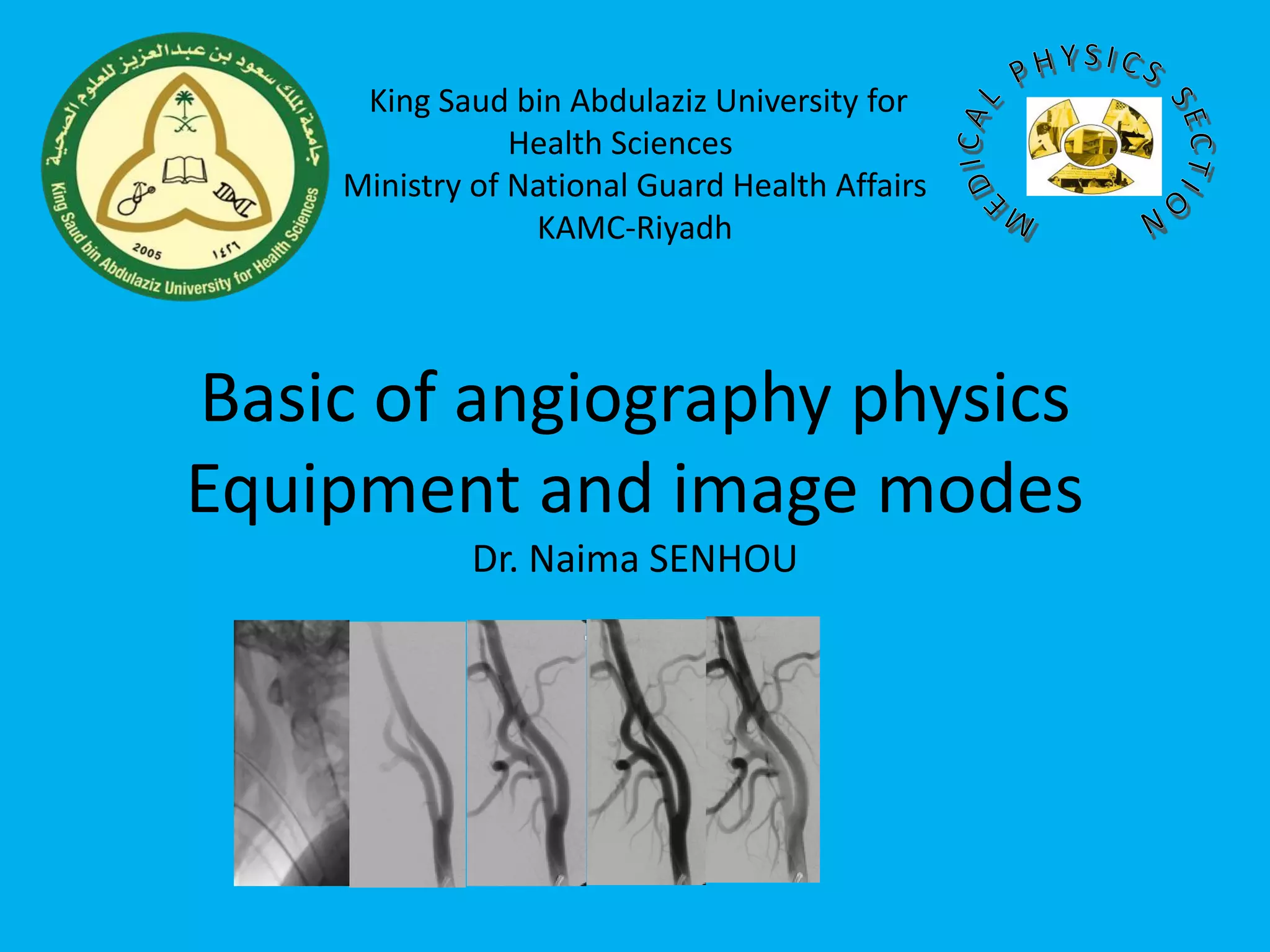
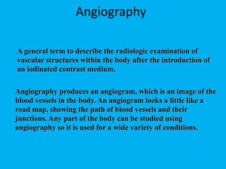
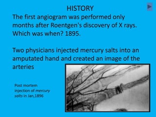
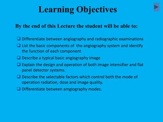
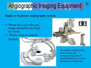
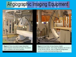
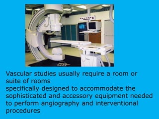
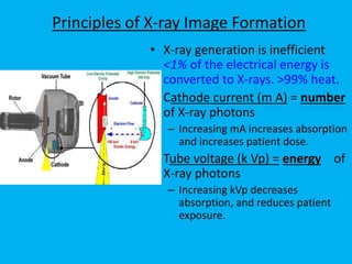
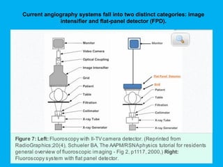
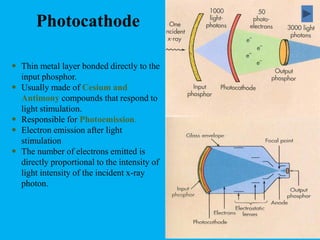
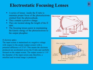
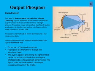
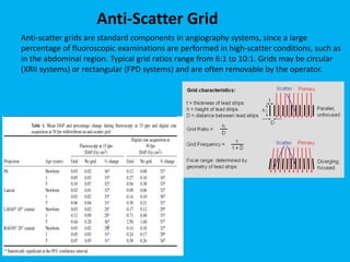
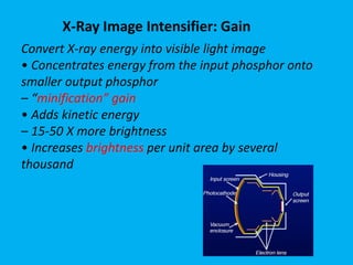
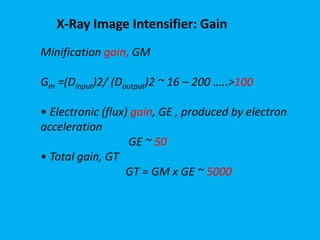
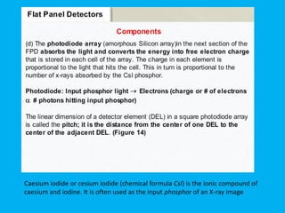
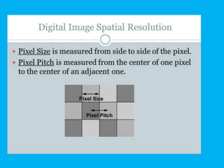
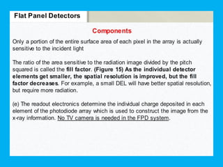
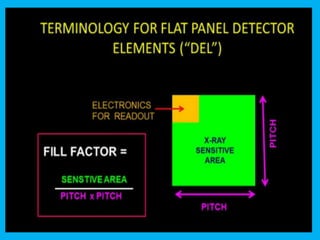
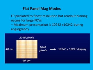
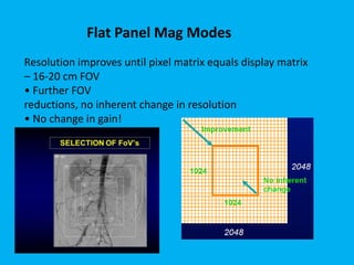
Basic of angiography physics
Equipment and image modes
Dr. Naima SENHOU
King Saud bin Abdulaziz University for
Health Sciences
Ministry of National Guard Health Affairs
KAMC-Riyadh
A general term to describe the radiologic examination of
vascular structures within the body after the introduction of
an iodinated contrast medium.
Angiography
Angiography produces an angiogram, which is an image of the
blood vessels in the body. An angiogram looks a little like a
road map, showing the path of blood vessels and their
junctions. Any part of the body can be studied using
angiography so it is used for a wide variety of conditions.
The first angiogram was performed only
months after Roentgen's discovery of X rays.
Which was when? 1895.
Two physicians injected mercury salts into an
amputated hand and created an image of the
arteries
HISTORY
Post mortem
injection of mercury
salts in Jan,1896
 Differentiate between angiography and radiographic examinations
 List the basic components of the angiography system and identify
the function of each component
 Describe a typical basic angiography image
 Explain the design and operation of both image intensifier and flat
panel detector systems.
 Describe the selectable factors which control both the mode of
operation radiation, dose and image quality.
 Differentiate between amgiography modes.
By the end of this Lecture the student will be able to:
Learning Objectives
 Where the x-ray tube and
image intensifier are fixed
to c-arms.
 Mostly used in surgical
theatres.
Single or bi-planar angiography system
The system consists of two
X-ray sources and
corresponding detector
panels positioned in a quasi-
orthogonal arrangement
Vascular studies usually require a room or
suite of rooms
specifically designed to accommodate the
sophisticated and accessory equipment needed
to perform angiography and interventional
procedures
Used for dynamic imaging
• X-ray tube operated at lower currents
– Factor of 50 to 100+ less
• X-ray quanta/cm2
– Radiography: 107/cm2
– Fluoroscopy: < 104 /cm2
• Statistical difference in the quality of the image
• Higher noise: lower signal
Fluoroscopy vs Radiography
Principles of X-ray Image Formation
• X-ray generation is inefficient
<1% of the electrical energy is
converted to X-rays. >99% heat.
• Cathode current (m A) = number
of X-ray photons
– Increasing mA increases absorption
and increases patient dose.
• Tube voltage (k Vp) = energy of
X-ray photons
– Increasing kVp decreases
absorption, and reduces patient
exposure.
• High-speed rotating anode tubes. The object of an
angiogram is to produce the highest quality
radiographs in the shortest time possible
• a 0.3 mm small focal spot will produce the best
detail.
• tube rating can be exceeded because of the rapid
succession of exposures needed
• usual to have a 0.6-mm focal spot tube.
X-ray tube for angiography machine
• This must be a three-phase or high-
frequency 12-pulse machine and at least
1000 mA to accommodate the rapid, short,
and high exposure values required in
angiography
Generator of angiography machines
Cost
Single and bi-plane angiography equipment
Image Acquisition Speed
Specialization
Space Requirements
Site Preparation
Because bi-plane systems capture image data from detectors on two axes, they are able to
acquire 3D images faster.
bi-plane system has a larger footprint than a single-plane system,
There needs to be a ceiling support installed for the second c-arm, additional
rigging is necessary, and the system has an overall larger footprint.
Bi-plane cath labs simply come with more "stuff", therefore they cost more than single-plane
systems.
Currently, service coverage for a bi-plane cath lab averages 25-30% higher than service for a
single-plane system.
If your facility is planning for a dedicated Neuro-Angiography & Stroke Interventional Labs,
for example, you'd be best served by a bi-plane system.
If your work leans in a more general/blended direction (balloons, stents, angio runs, etc.) a
single-plane lab can be flexible
Current angiography systems fall into two distinct categories: image
intensifier and flat-panel detector (FPD).
Angiography with image intensifiers
What is an Image Intensifier ?
A complex electronic imaging device
that receives the remnant beam and converts it
to light and increases the intensity of the light.
The image intensifier tube is contained
in a glass envelope in a vacuum and mounted in
a metallic container which provides protection
for the components
Image Intensifier
Schematics
Angiography with image intensifiers
1. II input window
• Convex metal shield that covers the input
face of the II
• Usually made of aluminium or titanium foil
(low Z metal) to allow x-ray beam to enter
with minimum attenuation
• Provides protection for sensitive input
components of the tube and maintains the
vacuum
Input
Phosphor
• Layer of sodium activated cesium iodide (CsI:Na)
for good x-ray absorption efficiency (70-90%)
• Channelled into tiny needle-like crystals (5µm in
diameter) with fibreoptic-like characteristics
• CsI:Na usually 400-500µm thick
• Each x-ray photon produces ~3000 light photons
in the blue spectrum
1. Constructed of cesium iodide.
2. Responsible for converting the incident
photon’s energy to a burst of visible light
photon.
◦ Similar to intensifying screens in cassettes.
3. Standard size varies from 10 - 35 cm.
◦ Normally used to identify the II tubes.
Photocathode
 Thin metal layer bonded directly to the
input phosphor.
 Usually made of Cesium and
Antimony compounds that respond to
light stimulation.
 Responsible for Photoemission.
 Electron emission after light
stimulation
 The number of electrons emitted is
directly proportional to the intensity of
light intensity of the incident x-ray
photon.
Electrostatic Focusing Lenses
II electron optics
The input screen is maintained at a negative voltage
with respect to the anode (output screen) with a
potential difference of 25 kV. This means the electrons
produced are accelerated across the II tube and carefully
focused on the output screen. The output screen is 1/10
the diameter of the input screen and, therefore, a
minified and inverted image is produced.
 A series of lenses inside the II tube to
maintain proper focus of the photoelectrons
emitted from the photocathode.
 They contain a positive charge.
 They are located along the length of the II
tube.
 The focusing lenses assist in maintaining
the kinetic energy of the photoelectrons to
the output phosphor.
Output Phosphor
Output Screen
Thin layer of silver-activated zinc cadmium sulphide
(ZnCdS:Ag) crystals deposited on the inner surface of the
output window that convert the electrons into light
photons. The output image is intensified significantly by the
acceleration of the electrons and the minification of the
image that occurs in the II tube.
The screen is normally 25-35 mm in diameter and a few
micrometres thick.
This surface of the output screen is coated in a very thin
layer of aluminium that:
• Forms part of the anode structure
• High speed electrons travel through the
aluminium layer
• The layer is opaque preventing the light emitted
by the phosphor from back-illuminating the
photocathode and degrading II performance. The
light is reflected back towards the output
increasing the gain of the II tube.
X-ray photons enter tube through aluminium or titanium window.
Hit input phosphor layer of sodium activated caesium iodide and
release light photons.
Light photons detected by photocathode, then release electrons
into the tube.
Electrons accelerated and focused onto the output screen (silver-
activated zinc cadmium sulphide crystals) as a minified and
inverted image.
Light photons released, then leave through the output window.
Summary
Patient tables must provide strength to support patients and are rated by the
manufacturer for a particular weight limit.
It is important that the table not absorb much radiation to avoid shadows, loss of signal
and loss of contrast in the image.
Carbon fiber technology offers a good combination of high strength and minimal
radiation absorption, making it an ideal table material.
Foam pads are often placed between the patient and the table for added comfort, yet
with minimal radiation absorption.
Patient Table and Pad
Beam Filtration
 It is common for fluoroscopic imaging systems to be equipped with
beam hardening filters between the X-ray tube exit port and the
collimator.
 Added aluminum and/or copper filtration can reduce skin dose at the
patient’s entrance surface, while a low kVp produces a spectral shape
that is well-matched to the barium or iodine k-edge for high contrast in
the anatomy of interest
In addition to beam shaping filters, many fluoroscopy systems have
“wedge” filters that are partially transparent to the X-ray beam. These
moveable filters attenuate the beam in regions selected by the operator
to reduce entrance dose and excessive image brightness
Variable X-ray Beam Filtration
In angiography, the collimation may be circular or
rectangular in shape, matching the shape of the image
receptor.
Collimation
When the operator selects a field of view, the collimator blade
positions automatically move under motor control to be just a
bit larger than the visible field.
When the source-to-image distance (SID) changes, the
collimator blades adjust to maintain the field of view and
minimize “spillover” radiation outside of the visible area. This
automatic collimation exists in both circular and rectangular
field of view systems.
Image Intensifier Mag Modes
Anti-scatter grids are standard components in angiography systems, since a large
percentage of fluoroscopic examinations are performed in high-scatter conditions, such as
in the abdominal region. Typical grid ratios range from 6:1 to 10:1. Grids may be circular
(XRII systems) or rectangular (FPD systems) and are often removable by the operator.
Anti-Scatter Grid
Convert X-ray energy into visible light image
• Concentrates energy from the input phosphor onto
smaller output phosphor
– “minification” gain
• Adds kinetic energy
– 15-50 X more brightness
• Increases brightness per unit area by several
thousand
X-Ray Image Intensifier: Gain
Minification gain, GM
Gm =(Dinput)2/ (Doutput)2 ~ 16 – 200 …..>100
• Electronic (flux) gain, GE , produced by electron
acceleration
GE ~ 50
• Total gain, GT
GT = GM x GE ~ 5000
Flat panel detectors utilise the same technology as digital
radiography in that there is a flat panel of detectors that provide a
direct electronic readout instead of requiring the conversion of
analogue to digital as is seen in the IITV.
Similar to digital radiography dynamic FP detectors can be direct or
indirect. However, they are more commonly indirect with a CsI:Tl x-
ray scintillator layer which is superimposed onto an a-Si high
resolution active matrix.
Flat panel detector
DIRECT AND INDIRECT FLAT PANEL DETECTORS
In indirect FPD,
The scintillator converts X-ray photons to
visible light usually an amorphous silicon (a-
Si) thin-film-transistor (TFT)
The intensity of the light is proportional to
the intensity of the X-ray photons. The
light emitted is detected by the TFT array,
which converts light energy to electrical
signal.
Direct FPD
One of the most common photoconductors isamorphous
selenium
(a-Se)
When X-ray photons traverse the photoconductor, they are absorbed
and electron-hole pairs proportional to the X-ray intensity are generated in the
solid state material.
The electrons and holes are directed by the electric field towards the TFT elements
Thin-film transistor(TFT)
Caesium iodide or cesium iodide (chemical formula CsI) is the ionic compound of
caesium and iodine. It is often used as the input phosphor of an X-ray image
Flat Panel Mag Modes
FP pixelated to finest resolution but readout binning
occurs for large FOVs
– Maximum presentation is 10242 x10242 during
angiography
Resolution improves until pixel matrix equals display matrix
– 16-20 cm FOV
• Further FOV
reductions, no inherent change in resolution
• No change in gain!
Flat Panel Mag Modes
Flat Panels: Dose Rate vs Field Size
Increases with 1/(field size)
– 15 x15 cm2 has 4x dose over 30 x 30
cm2
• No change in gain
• Empirically determined
• No change from II based systems
Pixel-binning is used in flat-panel (FP) x-ray detectors for
fluoroscopy to increase signal-to-noise ratio (SNR) and lower
digital data rates.
Flat panel Pixel-binning
This is a portion of a Mars Observer
Camera image of gullies cut into a
crater wall. The portion shown is
about 1 km across. The left hand
image has not been binned. The
right hand image has been binned 4
x 4. Note that binning reduces the
spatial resolution and the finest
details can no longer been seen.
No binning 4x4 binning
Effect of pixel binning
• Dynamic range of flat panel is greater than an
image intensifier
• Issues such as burnout (blooming) and
blackout (saturation into black) regions in
image is not as significant an issue with FD
as it is with II.
Dynamic Range
Smaller equipment.
Video signal emerges in digital form, reducing
electronic noise
Square or rectangular field (unlike circular field in IITV)
= better coverage in the corners
Better temporal resolution with matrix size of 2048 x
2048 pixels
Greyscale of 12 or 14 bits per pixel
Produces better quality images than IITV
Fewer artefacts such as geometrical distortion,
vignetting or contrast loss
Detective quantum efficiency 10-20% better than IITV
so can afford to reduce patient dose
Zoom option available (but doesn't increase spatial
resolution as it does in IITV)
Benefits of Flat panel detector
X-Ray Absorption Efficiency
TV MONITORS
• This practical and efficient viewing system was employed
because of the limitations of the mirror optic viewing
system.
TV monitors:
1. Enables viewing by multiple persons.
2. Monitors may be located in remote locations other than
the radiographic room.
3. Image brightness and contrast can be manipulated.
4. Images may be stored on different medium for reviewing
at a later time.
Angiography modes
 Manual Mode
◦ Allow the use to select the exact MA and KVp required
 AEC Mode
◦ Allow the unit to drive the KVp and MA to optimize
dose and image quality
 Pulsed Digital mode
◦ Modifies the fluoroscopic output by cutting by cutting
out exposure between pulses
◦ With the pulsed mode, it can be set to produce less than
the conventional 25 or 30 images per second. This
reduces the exposure rate.
Fluoroscopy -Modes of operation
57
Set the default fluoroscopy mode
to LOW
Lowest input dose needed to
generate a USABLE image
 Continuous Basic form of fluoroscopy; continuously ON x-ray beam
 High dose rate
• Allows exposure rates of up to 20 R/min
• Used to reduce noise in images
 Variable frame rate pulsed
30, 15, and 7.5 frames/sec operation allows lower temporal resolution for
parts of procedure
Angiography Modes of Operation
59
30 images in 1 second
X rays
In conventional continuous-beam angiography there is an
inherent blurred appearance of motion because the exposure
time of each image lasts the full 1/30th of a second at 30 frames
per second.
Continuous stream of X rays produces blurred
images in each frame
Images
Continuous mode
62
Lesson: Variable pulsed fluoroscopy is an important
tool to manage radiation dose to patients but the
actual effect on dose can be to enhance, decrease or
maintain dose levels. The actual effect must be
estimated by a qualified physicist so that variable
pulsed fluoroscopy can be properly employed.
Variable Pulsed
63
Understanding Variable Pulsed Fluoroscopy
Background: dynamic imaging captures many still
images every second and displays these still-frame
images in real-time succession to produce the
perception of motion. How these images are captured
and displayed can be manipulated to manage both dose
rate to the patient and dynamic image quality. Standard
imaging captures and displays 25 - 30 images per
second.
Pulsed mode
64
Each X ray pulse shown above has greater intensity
than continuous mode, but lasts for only 1/100th of a
second; no X rays are emitted between pulses; dose to
patient is same as that with continuous fluoroscopy
Pulsed fluoroscopy, no dose reduction
Images
Pulsed fluoroscopy produces sharp appearance of motion
because each of 30 images per second is captured in a pulse
or snapshot (e.g., 1/100th of a second).
X rays
30 images in 1 second
65
Each angiographic ‘run’ consists of multiple still images taken in quick succession.
67
Pulsed fluoroscopy, dose reduction at 15 pulses per second
Sharp appearance of motion captured at 15 images per second
in pulsed mode. Dose per pulse is same, but only half as many
pulses are used, thus dose is reduced by 50%. The tradeoff is a
slightly choppy appearance in motion since only half as many
images are shown per second
Images
X rays
15 images in 1 second
68
Pulsed fluoroscopy, dose enhancement at 15 pulses per second
Dose per pulse is enhanced because pulse intensity and
duration is increased. Overall dose is enhanced.
Images
X rays
15 images in 1 second
Reproduced with permission from Wagner LK, Houston, TX 2004.
Images
X rays
15 images in 1 second
69
Pulsed imaging controls:
Displaying 25–30 picture frames per second is usually
adequate for the transition from frame to frame to
appear smooth.
This is important for entertainment purposes, but not
necessarily required for medical procedures.
Manipulation of frame rate can be used to produce
enormous savings in dose accumulation.
Pulsed mode
70
Pulsed fluoroscopy at 7.5 images per second with
only 25% the dose
Pulsed fluoroscopy, dose reduction at 7.5 pulses per second
Images
X rays
Average 7.5
images in 1
second
Patient Dose Rate
Frame averaging
 Fluoroscopy images generally are noisy
 Sometimes beneficial to compromise resolution for lower noise images
 Digitize fluoroscopic images and perform real-time averaging in
computer memory for display
73
Influence of operation modes: from low mode to
cine, radiation / scatter dose rate could increase in
a factor of 10-15
Automatic brightness control
Purpose of ABC is to keep brightness of the image
constant at the monitor.
 Accomplished by regulating the X-Ray exposure rate
incident on the image receptor
Video signal itself can be used to sense light output
ABC can adjust both tube (mA) current and generator
voltage (kVp)
When the fluoroscopist takes his or her
footoff of the fluoroscopy pedal, rather than
seeing a blank monitor, last-image-hold
enables the continues display of the last
captured fluoroscopic image.
The image will by displayed until the
fluoroscopy beam is turned on again.
Last-Image-Hold
Fluoroscopy vs. Cineangiography
• Fluoroscopy
– A real-time X-ray image when it is
not necessary to record it.
– Requires less image quality than
does acquisition (cine)
– Images seen in motion, neuro-
psychology of vision integrates
frames effectively reducing
perceived image noise.
– With more noise tolerated, input
doses can be lower.
• Cineangiography
– Images are obtained at higher X-
ray input doses for acquisition
– Most units are calibrated such
that patient dose is 10- 15x
greater than fluoroscopy
– Thus, a single frame in cine is
equal to about one second of
fluoro
– A typical acquisition frame rate is
15 frames/sec
THANK YOU

basic of angiography physics and equipement.pdf

  • 1.
    Basic of angiographyphysics Equipment and image modes Dr. Naima SENHOU King Saud bin Abdulaziz University for Health Sciences Ministry of National Guard Health Affairs KAMC-Riyadh
  • 2.
    A general termto describe the radiologic examination of vascular structures within the body after the introduction of an iodinated contrast medium. Angiography Angiography produces an angiogram, which is an image of the blood vessels in the body. An angiogram looks a little like a road map, showing the path of blood vessels and their junctions. Any part of the body can be studied using angiography so it is used for a wide variety of conditions.
  • 3.
    The first angiogramwas performed only months after Roentgen's discovery of X rays. Which was when? 1895. Two physicians injected mercury salts into an amputated hand and created an image of the arteries HISTORY Post mortem injection of mercury salts in Jan,1896
  • 4.
     Differentiate betweenangiography and radiographic examinations  List the basic components of the angiography system and identify the function of each component  Describe a typical basic angiography image  Explain the design and operation of both image intensifier and flat panel detector systems.  Describe the selectable factors which control both the mode of operation radiation, dose and image quality.  Differentiate between amgiography modes. By the end of this Lecture the student will be able to: Learning Objectives
  • 5.
     Where thex-ray tube and image intensifier are fixed to c-arms.  Mostly used in surgical theatres. Single or bi-planar angiography system The system consists of two X-ray sources and corresponding detector panels positioned in a quasi- orthogonal arrangement
  • 7.
    Vascular studies usuallyrequire a room or suite of rooms specifically designed to accommodate the sophisticated and accessory equipment needed to perform angiography and interventional procedures
  • 8.
    Used for dynamicimaging • X-ray tube operated at lower currents – Factor of 50 to 100+ less • X-ray quanta/cm2 – Radiography: 107/cm2 – Fluoroscopy: < 104 /cm2 • Statistical difference in the quality of the image • Higher noise: lower signal Fluoroscopy vs Radiography
  • 9.
    Principles of X-rayImage Formation • X-ray generation is inefficient <1% of the electrical energy is converted to X-rays. >99% heat. • Cathode current (m A) = number of X-ray photons – Increasing mA increases absorption and increases patient dose. • Tube voltage (k Vp) = energy of X-ray photons – Increasing kVp decreases absorption, and reduces patient exposure.
  • 10.
    • High-speed rotatinganode tubes. The object of an angiogram is to produce the highest quality radiographs in the shortest time possible • a 0.3 mm small focal spot will produce the best detail. • tube rating can be exceeded because of the rapid succession of exposures needed • usual to have a 0.6-mm focal spot tube. X-ray tube for angiography machine
  • 11.
    • This mustbe a three-phase or high- frequency 12-pulse machine and at least 1000 mA to accommodate the rapid, short, and high exposure values required in angiography Generator of angiography machines
  • 12.
    Cost Single and bi-planeangiography equipment Image Acquisition Speed Specialization Space Requirements Site Preparation Because bi-plane systems capture image data from detectors on two axes, they are able to acquire 3D images faster. bi-plane system has a larger footprint than a single-plane system, There needs to be a ceiling support installed for the second c-arm, additional rigging is necessary, and the system has an overall larger footprint. Bi-plane cath labs simply come with more "stuff", therefore they cost more than single-plane systems. Currently, service coverage for a bi-plane cath lab averages 25-30% higher than service for a single-plane system. If your facility is planning for a dedicated Neuro-Angiography & Stroke Interventional Labs, for example, you'd be best served by a bi-plane system. If your work leans in a more general/blended direction (balloons, stents, angio runs, etc.) a single-plane lab can be flexible
  • 13.
    Current angiography systemsfall into two distinct categories: image intensifier and flat-panel detector (FPD).
  • 14.
    Angiography with imageintensifiers What is an Image Intensifier ? A complex electronic imaging device that receives the remnant beam and converts it to light and increases the intensity of the light. The image intensifier tube is contained in a glass envelope in a vacuum and mounted in a metallic container which provides protection for the components
  • 15.
    Image Intensifier Schematics Angiography withimage intensifiers 1. II input window • Convex metal shield that covers the input face of the II • Usually made of aluminium or titanium foil (low Z metal) to allow x-ray beam to enter with minimum attenuation • Provides protection for sensitive input components of the tube and maintains the vacuum
  • 16.
    Input Phosphor • Layer ofsodium activated cesium iodide (CsI:Na) for good x-ray absorption efficiency (70-90%) • Channelled into tiny needle-like crystals (5µm in diameter) with fibreoptic-like characteristics • CsI:Na usually 400-500µm thick • Each x-ray photon produces ~3000 light photons in the blue spectrum 1. Constructed of cesium iodide. 2. Responsible for converting the incident photon’s energy to a burst of visible light photon. ◦ Similar to intensifying screens in cassettes. 3. Standard size varies from 10 - 35 cm. ◦ Normally used to identify the II tubes.
  • 17.
    Photocathode  Thin metallayer bonded directly to the input phosphor.  Usually made of Cesium and Antimony compounds that respond to light stimulation.  Responsible for Photoemission.  Electron emission after light stimulation  The number of electrons emitted is directly proportional to the intensity of light intensity of the incident x-ray photon.
  • 18.
    Electrostatic Focusing Lenses IIelectron optics The input screen is maintained at a negative voltage with respect to the anode (output screen) with a potential difference of 25 kV. This means the electrons produced are accelerated across the II tube and carefully focused on the output screen. The output screen is 1/10 the diameter of the input screen and, therefore, a minified and inverted image is produced.  A series of lenses inside the II tube to maintain proper focus of the photoelectrons emitted from the photocathode.  They contain a positive charge.  They are located along the length of the II tube.  The focusing lenses assist in maintaining the kinetic energy of the photoelectrons to the output phosphor.
  • 19.
    Output Phosphor Output Screen Thinlayer of silver-activated zinc cadmium sulphide (ZnCdS:Ag) crystals deposited on the inner surface of the output window that convert the electrons into light photons. The output image is intensified significantly by the acceleration of the electrons and the minification of the image that occurs in the II tube. The screen is normally 25-35 mm in diameter and a few micrometres thick. This surface of the output screen is coated in a very thin layer of aluminium that: • Forms part of the anode structure • High speed electrons travel through the aluminium layer • The layer is opaque preventing the light emitted by the phosphor from back-illuminating the photocathode and degrading II performance. The light is reflected back towards the output increasing the gain of the II tube.
  • 20.
    X-ray photons entertube through aluminium or titanium window. Hit input phosphor layer of sodium activated caesium iodide and release light photons. Light photons detected by photocathode, then release electrons into the tube. Electrons accelerated and focused onto the output screen (silver- activated zinc cadmium sulphide crystals) as a minified and inverted image. Light photons released, then leave through the output window. Summary
  • 21.
    Patient tables mustprovide strength to support patients and are rated by the manufacturer for a particular weight limit. It is important that the table not absorb much radiation to avoid shadows, loss of signal and loss of contrast in the image. Carbon fiber technology offers a good combination of high strength and minimal radiation absorption, making it an ideal table material. Foam pads are often placed between the patient and the table for added comfort, yet with minimal radiation absorption. Patient Table and Pad
  • 22.
    Beam Filtration  Itis common for fluoroscopic imaging systems to be equipped with beam hardening filters between the X-ray tube exit port and the collimator.  Added aluminum and/or copper filtration can reduce skin dose at the patient’s entrance surface, while a low kVp produces a spectral shape that is well-matched to the barium or iodine k-edge for high contrast in the anatomy of interest In addition to beam shaping filters, many fluoroscopy systems have “wedge” filters that are partially transparent to the X-ray beam. These moveable filters attenuate the beam in regions selected by the operator to reduce entrance dose and excessive image brightness
  • 23.
  • 24.
    In angiography, thecollimation may be circular or rectangular in shape, matching the shape of the image receptor. Collimation When the operator selects a field of view, the collimator blade positions automatically move under motor control to be just a bit larger than the visible field. When the source-to-image distance (SID) changes, the collimator blades adjust to maintain the field of view and minimize “spillover” radiation outside of the visible area. This automatic collimation exists in both circular and rectangular field of view systems.
  • 26.
  • 29.
    Anti-scatter grids arestandard components in angiography systems, since a large percentage of fluoroscopic examinations are performed in high-scatter conditions, such as in the abdominal region. Typical grid ratios range from 6:1 to 10:1. Grids may be circular (XRII systems) or rectangular (FPD systems) and are often removable by the operator. Anti-Scatter Grid
  • 30.
    Convert X-ray energyinto visible light image • Concentrates energy from the input phosphor onto smaller output phosphor – “minification” gain • Adds kinetic energy – 15-50 X more brightness • Increases brightness per unit area by several thousand X-Ray Image Intensifier: Gain
  • 31.
    X-Ray Image Intensifier:Gain Minification gain, GM Gm =(Dinput)2/ (Doutput)2 ~ 16 – 200 …..>100 • Electronic (flux) gain, GE , produced by electron acceleration GE ~ 50 • Total gain, GT GT = GM x GE ~ 5000
  • 32.
    Flat panel detectorsutilise the same technology as digital radiography in that there is a flat panel of detectors that provide a direct electronic readout instead of requiring the conversion of analogue to digital as is seen in the IITV. Similar to digital radiography dynamic FP detectors can be direct or indirect. However, they are more commonly indirect with a CsI:Tl x- ray scintillator layer which is superimposed onto an a-Si high resolution active matrix. Flat panel detector
  • 35.
    DIRECT AND INDIRECTFLAT PANEL DETECTORS In indirect FPD, The scintillator converts X-ray photons to visible light usually an amorphous silicon (a- Si) thin-film-transistor (TFT) The intensity of the light is proportional to the intensity of the X-ray photons. The light emitted is detected by the TFT array, which converts light energy to electrical signal. Direct FPD One of the most common photoconductors isamorphous selenium (a-Se) When X-ray photons traverse the photoconductor, they are absorbed and electron-hole pairs proportional to the X-ray intensity are generated in the solid state material. The electrons and holes are directed by the electric field towards the TFT elements
  • 36.
  • 37.
    Caesium iodide orcesium iodide (chemical formula CsI) is the ionic compound of caesium and iodine. It is often used as the input phosphor of an X-ray image
  • 41.
    Flat Panel MagModes FP pixelated to finest resolution but readout binning occurs for large FOVs – Maximum presentation is 10242 x10242 during angiography
  • 42.
    Resolution improves untilpixel matrix equals display matrix – 16-20 cm FOV • Further FOV reductions, no inherent change in resolution • No change in gain! Flat Panel Mag Modes
  • 43.
    Flat Panels: DoseRate vs Field Size Increases with 1/(field size) – 15 x15 cm2 has 4x dose over 30 x 30 cm2 • No change in gain • Empirically determined • No change from II based systems
  • 46.
    Pixel-binning is usedin flat-panel (FP) x-ray detectors for fluoroscopy to increase signal-to-noise ratio (SNR) and lower digital data rates. Flat panel Pixel-binning
  • 49.
    This is aportion of a Mars Observer Camera image of gullies cut into a crater wall. The portion shown is about 1 km across. The left hand image has not been binned. The right hand image has been binned 4 x 4. Note that binning reduces the spatial resolution and the finest details can no longer been seen. No binning 4x4 binning Effect of pixel binning
  • 50.
    • Dynamic rangeof flat panel is greater than an image intensifier • Issues such as burnout (blooming) and blackout (saturation into black) regions in image is not as significant an issue with FD as it is with II. Dynamic Range
  • 51.
    Smaller equipment. Video signalemerges in digital form, reducing electronic noise Square or rectangular field (unlike circular field in IITV) = better coverage in the corners Better temporal resolution with matrix size of 2048 x 2048 pixels Greyscale of 12 or 14 bits per pixel Produces better quality images than IITV Fewer artefacts such as geometrical distortion, vignetting or contrast loss Detective quantum efficiency 10-20% better than IITV so can afford to reduce patient dose Zoom option available (but doesn't increase spatial resolution as it does in IITV) Benefits of Flat panel detector
  • 53.
  • 54.
    TV MONITORS • Thispractical and efficient viewing system was employed because of the limitations of the mirror optic viewing system. TV monitors: 1. Enables viewing by multiple persons. 2. Monitors may be located in remote locations other than the radiographic room. 3. Image brightness and contrast can be manipulated. 4. Images may be stored on different medium for reviewing at a later time.
  • 55.
  • 56.
     Manual Mode ◦Allow the use to select the exact MA and KVp required  AEC Mode ◦ Allow the unit to drive the KVp and MA to optimize dose and image quality  Pulsed Digital mode ◦ Modifies the fluoroscopic output by cutting by cutting out exposure between pulses ◦ With the pulsed mode, it can be set to produce less than the conventional 25 or 30 images per second. This reduces the exposure rate. Fluoroscopy -Modes of operation
  • 57.
    57 Set the defaultfluoroscopy mode to LOW Lowest input dose needed to generate a USABLE image
  • 58.
     Continuous Basicform of fluoroscopy; continuously ON x-ray beam  High dose rate • Allows exposure rates of up to 20 R/min • Used to reduce noise in images  Variable frame rate pulsed 30, 15, and 7.5 frames/sec operation allows lower temporal resolution for parts of procedure Angiography Modes of Operation
  • 59.
    59 30 images in1 second X rays In conventional continuous-beam angiography there is an inherent blurred appearance of motion because the exposure time of each image lasts the full 1/30th of a second at 30 frames per second. Continuous stream of X rays produces blurred images in each frame Images Continuous mode
  • 62.
    62 Lesson: Variable pulsedfluoroscopy is an important tool to manage radiation dose to patients but the actual effect on dose can be to enhance, decrease or maintain dose levels. The actual effect must be estimated by a qualified physicist so that variable pulsed fluoroscopy can be properly employed. Variable Pulsed
  • 63.
    63 Understanding Variable PulsedFluoroscopy Background: dynamic imaging captures many still images every second and displays these still-frame images in real-time succession to produce the perception of motion. How these images are captured and displayed can be manipulated to manage both dose rate to the patient and dynamic image quality. Standard imaging captures and displays 25 - 30 images per second. Pulsed mode
  • 64.
    64 Each X raypulse shown above has greater intensity than continuous mode, but lasts for only 1/100th of a second; no X rays are emitted between pulses; dose to patient is same as that with continuous fluoroscopy Pulsed fluoroscopy, no dose reduction Images Pulsed fluoroscopy produces sharp appearance of motion because each of 30 images per second is captured in a pulse or snapshot (e.g., 1/100th of a second). X rays 30 images in 1 second
  • 65.
    65 Each angiographic ‘run’consists of multiple still images taken in quick succession.
  • 67.
    67 Pulsed fluoroscopy, dosereduction at 15 pulses per second Sharp appearance of motion captured at 15 images per second in pulsed mode. Dose per pulse is same, but only half as many pulses are used, thus dose is reduced by 50%. The tradeoff is a slightly choppy appearance in motion since only half as many images are shown per second Images X rays 15 images in 1 second
  • 68.
    68 Pulsed fluoroscopy, doseenhancement at 15 pulses per second Dose per pulse is enhanced because pulse intensity and duration is increased. Overall dose is enhanced. Images X rays 15 images in 1 second Reproduced with permission from Wagner LK, Houston, TX 2004. Images X rays 15 images in 1 second
  • 69.
    69 Pulsed imaging controls: Displaying25–30 picture frames per second is usually adequate for the transition from frame to frame to appear smooth. This is important for entertainment purposes, but not necessarily required for medical procedures. Manipulation of frame rate can be used to produce enormous savings in dose accumulation. Pulsed mode
  • 70.
    70 Pulsed fluoroscopy at7.5 images per second with only 25% the dose Pulsed fluoroscopy, dose reduction at 7.5 pulses per second Images X rays Average 7.5 images in 1 second
  • 71.
  • 72.
    Frame averaging  Fluoroscopyimages generally are noisy  Sometimes beneficial to compromise resolution for lower noise images  Digitize fluoroscopic images and perform real-time averaging in computer memory for display
  • 73.
    73 Influence of operationmodes: from low mode to cine, radiation / scatter dose rate could increase in a factor of 10-15
  • 74.
    Automatic brightness control Purposeof ABC is to keep brightness of the image constant at the monitor.  Accomplished by regulating the X-Ray exposure rate incident on the image receptor Video signal itself can be used to sense light output ABC can adjust both tube (mA) current and generator voltage (kVp)
  • 77.
    When the fluoroscopisttakes his or her footoff of the fluoroscopy pedal, rather than seeing a blank monitor, last-image-hold enables the continues display of the last captured fluoroscopic image. The image will by displayed until the fluoroscopy beam is turned on again. Last-Image-Hold
  • 78.
    Fluoroscopy vs. Cineangiography •Fluoroscopy – A real-time X-ray image when it is not necessary to record it. – Requires less image quality than does acquisition (cine) – Images seen in motion, neuro- psychology of vision integrates frames effectively reducing perceived image noise. – With more noise tolerated, input doses can be lower. • Cineangiography – Images are obtained at higher X- ray input doses for acquisition – Most units are calibrated such that patient dose is 10- 15x greater than fluoroscopy – Thus, a single frame in cine is equal to about one second of fluoro – A typical acquisition frame rate is 15 frames/sec
  • 79.