The document summarizes the key components and functioning of fluoroscopic imaging equipment, specifically x-ray image intensifiers. It describes:
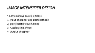
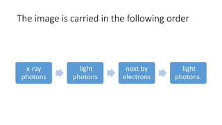
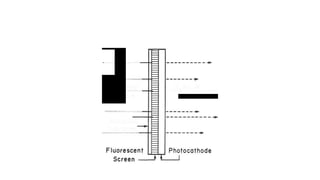
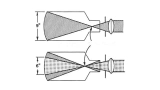
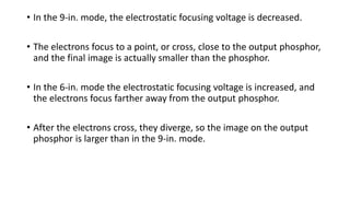
1) The four basic elements of an image intensifier - input phosphor, photocathode, electrostatic focusing lens, and output phosphor. X-ray photons are converted to light photons which eject electrons that are focused to the output phosphor.
2) Key materials used - the input phosphor is cesium iodide which converts x-rays to light efficiently. The output phosphor is zinc sulfide which produces a brighter image.
3) Benefits of image intensifiers over earlier fluoroscopy include a brighter image from electron multiplication and the ability to view images