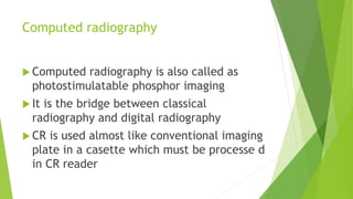
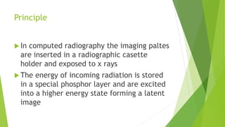
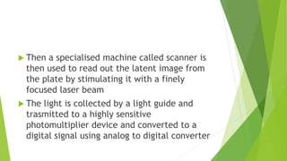
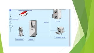
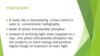
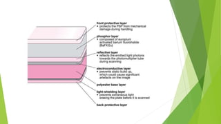
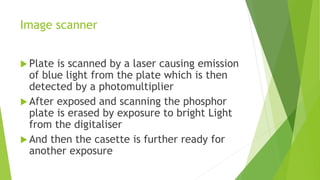
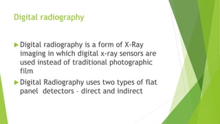
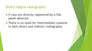
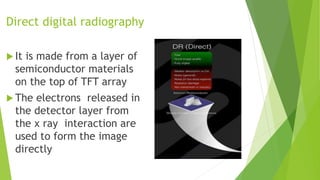
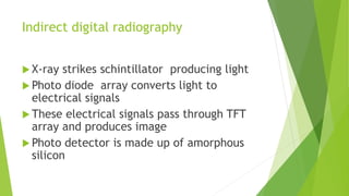
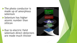
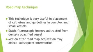
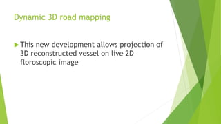
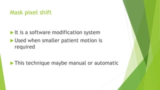
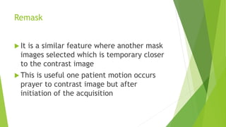
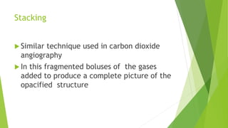
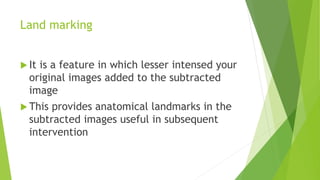
Computed radiography
and digital radiography
and digital subtraction
angiography
Moderator – Dr Vijayalakshmi MDRD
Presentor – Dr Swetha
Computed radiography
 Computed radiography is also called as
photostimulatable phosphor imaging
 It is the bridge between classical
radiography and digital radiography
 CR is used almost like conventional imaging
plate in a casette which must be processe d
in CR reader
CR system
 Image plate
 X ray or gamma source
 Image reader
 Photo multiplier tube
 Computer console or work station
Principle
 In computed radiography the imaging paltes
are inserted in a radiographic casette
holder and exposed to x rays
 The energy of incoming radiation is stored
in a special phosphor layer and are excited
into a higher energy state forming a latent
image
 Then a specialised machine called scanner is
then used to read out the latent image from
the plate by stimulating it with a finely
focused laser beam
 The light is collected by a light guide and
trasmitted to a highly sensitive
photomultiplier device and converted to a
digital signal using analog to digital converter
Steps of CR processing
Imaging plate
 It looks like a intensyfying screen which is
seen in conventional radiography
 Made of photo stimulatable phosphor
 Instead of emitting light when exposed to x
rays ,this photo stimulatable phosphor has
the property to store energy and produce
digital image on exposure to laser light
Image scanner
 Plate is scanned by a laser causing emission
of blue light from the plate which is then
detected by a photomultiplier
 After exposed and scanning the phosphor
plate is erased by exposure to bright Light
from the digitaliser
 And then the casette is further ready for
another exposure
Photomultiplier tube
 A photo multiplier tube useful for light
detection of very weak signals is a photo
emissive device in which the absorbtion of
a photon results in the emmision of an
electron
 These detectors work by amplifying the
electrons generated by a photocathode
exposed to a photon flux
Advantages
Post processing manipulation and storage of
images is easy
 Repeat examinations are reduced
 consistent high quality images
 Ability to deliver images quickly
 To acquire images
 Increased savings
 Reduction in exposure and processing time
 Digital magnification can be done
 Global data exchange
Disadvantages
 Initial cost
 Additional cost that is service and
maintenance
 Plate sensitive to fogging
Digital radiography
 Digital radiography is a form of X-Ray
imaging in which digital x-ray sensors are
used instead of traditional photographic
film
 Digital Radiography uses two types of flat
panel detectors – direct and indirect
Flat panel detectors
Direct digital radiography
 X-rays are directly registered by a flat
panel detector
 There is no need for intermediate cassette
in both direct and indirect radiography
Direct digital radiography
 It is made from a layer of
semiconductor materials
on the top of TFT array
 The electrons released in
the detector layer from
the x ray interaction are
used to form the image
directly
Indirect digital radiography
 X-ray strikes schintillator producing light
 Photo diode array converts light to
electrical signals
 These electrical signals pass through TFT
array and produces image
 Photo detector is made up of amorphous
silicon
 The photo conductor is
made up of amorphous
selenium
 Selenium has higher
atomic number than
sillicon
 Due to electric field
selenium direct detectors
are made much thicker
Advantages
 Receptor provides direct digital output
 Potentially lower patient dose than CR
 High latitude as per CR
 No processor or reader is required
 Less than 15 seconds
 Much less work for technologist
Digital subtraction angiography
 It is a digital imaging technique for better
visualisation of contrast will blood vessels
 In this technique pre contrast imagesare
digitally subtracted from post contrast
image to provide background separation
Process involved in DSA
 1. Preprocessing – digitalisation analogue to
digital conversion
 2 . Processing – subtraction techniques
 3 . Post processing – manipulation to
enhance visibility
 4 . Information extraction
Processing
 Mask mode subtraction
 Time interval difference subtraction
 Dual energy subtraction
 Hybrid subtraction
Mass mode subtraction
 Most widely used process of subtraction
 In this temporal subtraction is done
 It involves initial acquisition of a frame of region of
interest
 Then a second images taken and stored as a mask
image
 This mask images subtracted from subsequently
acquired images and show only contrast will
structures
 If any moment occurs after acquisition of
mass image mis registration occurs in the
subtracted images
 This can be overcome to some extent by
pixel shifting
Time interval difference subtraction
 Another mode of temporal subtraction
where a consecutive previous frame is
subtracted from current frame
 This technique is very useful in cardiac
imaging where there is rapid motion
Dual energy subtraction
 Another technique in which the region of
interest is exposed to higher and lower kV
at very short intervals
 Then the higher kV image is subtracted
from lower kV image to produce the image
 This technique has advantage of
elimination of motion artefacts
 Does not require the acquisition of images
before arrival of contrast material as in
Mask subtraction
 Provides selective cancellation
Problems of dual energy subtraction
 More complex x ray machine is needed to
rapidly switch kV and mA
 Due to difference in beam hardening in soft
tissue and bone improper subtraction
results
Hybrid subtraction
 It is a combination of dual energy and
temporal subtraction
 It has advantage that it eliminate effect of
patient motion
Techniques used in DSA
 Road map technique
 Fluoroscopy fade technique
 Dynamic 3D road mapping technique
Road map technique
 This technique is very useful in placement
of catheters and guidelines in complex and
small Vessels
 Static fluoroscopic images subtracted from
densely opacified vessel
 Motion after road map acquisition may
affect subsequent intervention
Fluoroscopy fade technique
 In this technique reference DSA images
overlayed on a real time fluoroscopic
image
Dynamic 3D road mapping
 This new development allows projection of
3D reconstructed vessel on live 2D
floroscopic image
Peripheral DSA
 Can be performed with single contrast
injection using stepping technique
 Two types – stepping table technique
. Stepping gantry method
Stepping table technique
 In this , table moves into Three stations
with X ray tubes with detector remaining
fixed
Stepping gantry method
 In this the tube detector or image
intensifier moves keeping the table fixed
 In both method precontrast images are
accquired at different Stations and stored
as mask images
 Subsequently matching post contrast
images are taken at the same position And
subtracted from the corresponding mask
image
Uses
 Significantly reduce the use of contrast
 Reduce the examination time
 Increased chance of movement between
pre and post contrast images
Post processing
 Mask pixel shift
 Remask
 Image summation
 Stacking
 Landmarking
Mask pixel shift
 It is a software modification system
 Used when smaller patient motion is
required
 This technique maybe manual or automatic
Remask
 It is a similar feature where another mask
images selected which is temporary closer
to the contrast image
 This is useful one patient motion occurs
prayer to contrast image but after
initiation of the acquisition
Image summation
 It is a property in which two or more
frames of DSA acquisition are summed into
the single image
Stacking
 Similar technique used in carbon dioxide
angiography
 In this fragmented boluses of the gases
added to produce a complete picture of the
opacified structure
Land marking
 It is a feature in which lesser intensed your
original images added to the subtracted
image
 This provides anatomical landmarks in the
subtracted images useful in subsequent
intervention
Thank you

computed radiography, digital radiography

  • 1.
    Computed radiography and digitalradiography and digital subtraction angiography Moderator – Dr Vijayalakshmi MDRD Presentor – Dr Swetha
  • 2.
    Computed radiography  Computedradiography is also called as photostimulatable phosphor imaging  It is the bridge between classical radiography and digital radiography  CR is used almost like conventional imaging plate in a casette which must be processe d in CR reader
  • 3.
    CR system  Imageplate  X ray or gamma source  Image reader  Photo multiplier tube  Computer console or work station
  • 4.
    Principle  In computedradiography the imaging paltes are inserted in a radiographic casette holder and exposed to x rays  The energy of incoming radiation is stored in a special phosphor layer and are excited into a higher energy state forming a latent image
  • 5.
     Then aspecialised machine called scanner is then used to read out the latent image from the plate by stimulating it with a finely focused laser beam  The light is collected by a light guide and trasmitted to a highly sensitive photomultiplier device and converted to a digital signal using analog to digital converter
  • 6.
    Steps of CRprocessing
  • 8.
    Imaging plate  Itlooks like a intensyfying screen which is seen in conventional radiography  Made of photo stimulatable phosphor  Instead of emitting light when exposed to x rays ,this photo stimulatable phosphor has the property to store energy and produce digital image on exposure to laser light
  • 10.
    Image scanner  Plateis scanned by a laser causing emission of blue light from the plate which is then detected by a photomultiplier  After exposed and scanning the phosphor plate is erased by exposure to bright Light from the digitaliser  And then the casette is further ready for another exposure
  • 11.
    Photomultiplier tube  Aphoto multiplier tube useful for light detection of very weak signals is a photo emissive device in which the absorbtion of a photon results in the emmision of an electron  These detectors work by amplifying the electrons generated by a photocathode exposed to a photon flux
  • 12.
    Advantages Post processing manipulationand storage of images is easy  Repeat examinations are reduced  consistent high quality images
  • 13.
     Ability todeliver images quickly  To acquire images  Increased savings  Reduction in exposure and processing time  Digital magnification can be done  Global data exchange
  • 14.
    Disadvantages  Initial cost Additional cost that is service and maintenance  Plate sensitive to fogging
  • 15.
    Digital radiography  Digitalradiography is a form of X-Ray imaging in which digital x-ray sensors are used instead of traditional photographic film  Digital Radiography uses two types of flat panel detectors – direct and indirect
  • 16.
  • 18.
    Direct digital radiography X-rays are directly registered by a flat panel detector  There is no need for intermediate cassette in both direct and indirect radiography
  • 19.
    Direct digital radiography It is made from a layer of semiconductor materials on the top of TFT array  The electrons released in the detector layer from the x ray interaction are used to form the image directly
  • 20.
    Indirect digital radiography X-ray strikes schintillator producing light  Photo diode array converts light to electrical signals  These electrical signals pass through TFT array and produces image  Photo detector is made up of amorphous silicon
  • 21.
     The photoconductor is made up of amorphous selenium  Selenium has higher atomic number than sillicon  Due to electric field selenium direct detectors are made much thicker
  • 22.
    Advantages  Receptor providesdirect digital output  Potentially lower patient dose than CR  High latitude as per CR  No processor or reader is required  Less than 15 seconds  Much less work for technologist
  • 23.
    Digital subtraction angiography It is a digital imaging technique for better visualisation of contrast will blood vessels  In this technique pre contrast imagesare digitally subtracted from post contrast image to provide background separation
  • 24.
    Process involved inDSA  1. Preprocessing – digitalisation analogue to digital conversion  2 . Processing – subtraction techniques  3 . Post processing – manipulation to enhance visibility  4 . Information extraction
  • 25.
    Processing  Mask modesubtraction  Time interval difference subtraction  Dual energy subtraction  Hybrid subtraction
  • 26.
    Mass mode subtraction Most widely used process of subtraction  In this temporal subtraction is done  It involves initial acquisition of a frame of region of interest  Then a second images taken and stored as a mask image  This mask images subtracted from subsequently acquired images and show only contrast will structures
  • 27.
     If anymoment occurs after acquisition of mass image mis registration occurs in the subtracted images  This can be overcome to some extent by pixel shifting
  • 28.
    Time interval differencesubtraction  Another mode of temporal subtraction where a consecutive previous frame is subtracted from current frame  This technique is very useful in cardiac imaging where there is rapid motion
  • 29.
    Dual energy subtraction Another technique in which the region of interest is exposed to higher and lower kV at very short intervals  Then the higher kV image is subtracted from lower kV image to produce the image
  • 30.
     This techniquehas advantage of elimination of motion artefacts  Does not require the acquisition of images before arrival of contrast material as in Mask subtraction  Provides selective cancellation
  • 31.
    Problems of dualenergy subtraction  More complex x ray machine is needed to rapidly switch kV and mA  Due to difference in beam hardening in soft tissue and bone improper subtraction results
  • 32.
    Hybrid subtraction  Itis a combination of dual energy and temporal subtraction  It has advantage that it eliminate effect of patient motion
  • 33.
    Techniques used inDSA  Road map technique  Fluoroscopy fade technique  Dynamic 3D road mapping technique
  • 34.
    Road map technique This technique is very useful in placement of catheters and guidelines in complex and small Vessels  Static fluoroscopic images subtracted from densely opacified vessel  Motion after road map acquisition may affect subsequent intervention
  • 35.
    Fluoroscopy fade technique In this technique reference DSA images overlayed on a real time fluoroscopic image
  • 36.
    Dynamic 3D roadmapping  This new development allows projection of 3D reconstructed vessel on live 2D floroscopic image
  • 37.
    Peripheral DSA  Canbe performed with single contrast injection using stepping technique  Two types – stepping table technique . Stepping gantry method
  • 38.
    Stepping table technique In this , table moves into Three stations with X ray tubes with detector remaining fixed
  • 39.
    Stepping gantry method In this the tube detector or image intensifier moves keeping the table fixed
  • 40.
     In bothmethod precontrast images are accquired at different Stations and stored as mask images  Subsequently matching post contrast images are taken at the same position And subtracted from the corresponding mask image
  • 41.
    Uses  Significantly reducethe use of contrast  Reduce the examination time
  • 42.
     Increased chanceof movement between pre and post contrast images
  • 43.
    Post processing  Maskpixel shift  Remask  Image summation  Stacking  Landmarking
  • 44.
    Mask pixel shift It is a software modification system  Used when smaller patient motion is required  This technique maybe manual or automatic
  • 45.
    Remask  It isa similar feature where another mask images selected which is temporary closer to the contrast image  This is useful one patient motion occurs prayer to contrast image but after initiation of the acquisition
  • 46.
    Image summation  Itis a property in which two or more frames of DSA acquisition are summed into the single image
  • 47.
    Stacking  Similar techniqueused in carbon dioxide angiography  In this fragmented boluses of the gases added to produce a complete picture of the opacified structure
  • 48.
    Land marking  Itis a feature in which lesser intensed your original images added to the subtracted image  This provides anatomical landmarks in the subtracted images useful in subsequent intervention
  • 49.