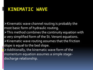
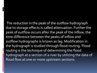
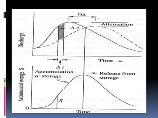
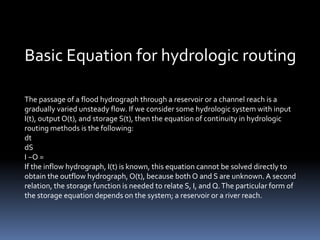
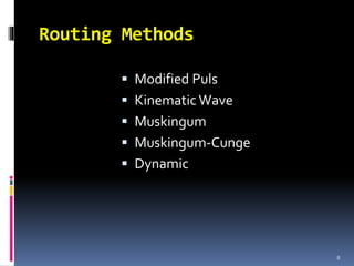
FLOOD ROUTING
PREPARED BY-
PERINWASNIK
Introduction
A flood is an unusually high stage in a river –
normally the level at which the river overflows its
banks and inundates the adjoining area.The
damages caused by floods in terms of loss of life,
property and economic loss due to disruption of
economic activity are very high. Flood peak
values are required in the design bridges, culvert
waterways, spillways for dams, and estimation
of scour at a hydraulic structure.
 At a given location in a stream, flood peaks
vary from year to year and their magnitude
constitutes a hydrologic series.To estimate the
magnitude of a flood peak the following
methods are adopted:
1. Rational method
2. Empirical equations
3. Flood frequency studies
4. Unit hydrograph technique
FLOOD ROUTING
The flood hydrograph is in fact a wave.The stage
and discharge hydrographs represent the
passage of waves of stream depth and discharge
respectively.As this wave moves down, the shape
of the wave gets modified due to channel
storage, resistance, lateral addition or withdrawal
of flows etc.When a flood wave passes through a
reservoir its peak is attenuated and the time base
is enlarged due to effect of storage
The reduction in the peak of the outflow hydrograph
due to storage effects is called attenuation. Further the
peak of outflow occurs after the peak of the inflow; the
time difference between the peaks of inflow and
outflow hydrographs is known as lag. Modification in
the hydrograph is studied through flood routing. Flood
routing is the technique of determining the flood
hydrograph at a section of a river by utilizing the data of
flood flow at one or more upstream sections.
Basic Equation for hydrologic routing
The passage of a flood hydrograph through a reservoir or a channel reach is a
gradually varied unsteady flow. If we consider some hydrologic system with input
I(t), output O(t), and storage S(t), then the equation of continuity in hydrologic
routing methods is the following:
dt
dS
I −O =
If the inflow hydrograph, I(t) is known, this equation cannot be solved directly to
obtain the outflow hydrograph, O(t), because both O and S are unknown. A second
relation, the storage function is needed to relate S, I, and Q.The particular form of
the storage equation depends on the system; a reservoir or a river reach.
Routing Methods
 Modified Puls
 Kinematic Wave
 Muskingum
 Muskingum-Cunge
 Dynamic
8
MODIFIED PULS
The modified puls routing method is probably most
often applied to reservoir routing
The method may also be applied to river routing for
certain channel situations.
The modified puls method is also referred to as the
storage-indication method.
The heart of the modified puls equation is found by
considering the finite difference form of the continuity
equation.
Modified Puls
10
t
S-S
=
2
O+O(
-
2
I+I 122121

Continuity Equation
O+
t
S2
=O-
t
S2
+I+I 2
2
1
1
21








Rewritten
The solution to the modified puls method is
accomplished by developing a graph (or table) of O -vs-
[2S/Δt + O]. In order to do this, a stage-discharge-
storage relationship must be known, assumed, or
derived.
KINEMATIC WAVE
Kinematic wave channel routing is probably the
most basic form of hydraulic routing.
This method combines the continuity equation with
a very simplified form of the St.Venant equations.
Kinematic wave routing assumes that the friction
slope is equal to the bed slope.
Additionally, the kinematic wave form of the
momentum equation assumes a simple stage-
discharge relationship.
MUSKINGUM NOTES :
•The method assumes a single stage-discharge relationship.
•In other words, for any given discharge,Q, there can be only one
stage height.
•This assumption may not be entirely valid for certain flow
situations.
•For instance, the friction slope on the rising side of a hydrograph
for a given flow, Q, may be quite different than for the recession
side of the hydrograph for the same given flow, Q.
•This causes an effect known as hysteresis, which can introduce
errors into the storage assumptions of this method.
Muskingum-Cunge
 Muskingum-Cunge formulation is similar to the
Muskingum type formulation
 The Muskingum-Cunge derivation begins with the
continuity equation and includes the diffusion form
of the momentum equation.
 These equations are combined and linearized,
13
Muskingum-Cunge
“working equation”
where :
Q = discharge
t = time
x = distance along channel
qx = lateral inflow
c = wave celerity
m = hydraulic diffusivity
14
Latcq
x
Q
x
Q
t
Q









2
2

Full Dynamic Wave Equations
 The solution of the St.Venant equations is known as
dynamic routing.
 Dynamic routing is generally the standard to which
other methods are measured or compared.
 The solution of the St.Venant equations is generally
accomplished via one of two methods : 1) the
method of characteristics and 2) direct methods
(implicit and explicit).
 It may be fair to say that regardless of the method
of solution, a computer is absolutely necessary as
the solutions are quite time consuming.
 J. J. Stoker (1953, 1957) is generally credited for
initially attempting to solve the St.Venant
equations using a high speed computer.
15
THANK YOU

Flood routing

  • 1.
  • 2.
    Introduction A flood isan unusually high stage in a river – normally the level at which the river overflows its banks and inundates the adjoining area.The damages caused by floods in terms of loss of life, property and economic loss due to disruption of economic activity are very high. Flood peak values are required in the design bridges, culvert waterways, spillways for dams, and estimation of scour at a hydraulic structure.
  • 3.
     At agiven location in a stream, flood peaks vary from year to year and their magnitude constitutes a hydrologic series.To estimate the magnitude of a flood peak the following methods are adopted: 1. Rational method 2. Empirical equations 3. Flood frequency studies 4. Unit hydrograph technique
  • 4.
    FLOOD ROUTING The floodhydrograph is in fact a wave.The stage and discharge hydrographs represent the passage of waves of stream depth and discharge respectively.As this wave moves down, the shape of the wave gets modified due to channel storage, resistance, lateral addition or withdrawal of flows etc.When a flood wave passes through a reservoir its peak is attenuated and the time base is enlarged due to effect of storage
  • 5.
    The reduction inthe peak of the outflow hydrograph due to storage effects is called attenuation. Further the peak of outflow occurs after the peak of the inflow; the time difference between the peaks of inflow and outflow hydrographs is known as lag. Modification in the hydrograph is studied through flood routing. Flood routing is the technique of determining the flood hydrograph at a section of a river by utilizing the data of flood flow at one or more upstream sections.
  • 7.
    Basic Equation forhydrologic routing The passage of a flood hydrograph through a reservoir or a channel reach is a gradually varied unsteady flow. If we consider some hydrologic system with input I(t), output O(t), and storage S(t), then the equation of continuity in hydrologic routing methods is the following: dt dS I −O = If the inflow hydrograph, I(t) is known, this equation cannot be solved directly to obtain the outflow hydrograph, O(t), because both O and S are unknown. A second relation, the storage function is needed to relate S, I, and Q.The particular form of the storage equation depends on the system; a reservoir or a river reach.
  • 8.
    Routing Methods  ModifiedPuls  Kinematic Wave  Muskingum  Muskingum-Cunge  Dynamic 8
  • 9.
    MODIFIED PULS The modifiedpuls routing method is probably most often applied to reservoir routing The method may also be applied to river routing for certain channel situations. The modified puls method is also referred to as the storage-indication method. The heart of the modified puls equation is found by considering the finite difference form of the continuity equation.
  • 10.
    Modified Puls 10 t S-S = 2 O+O( - 2 I+I 122121  ContinuityEquation O+ t S2 =O- t S2 +I+I 2 2 1 1 21         Rewritten The solution to the modified puls method is accomplished by developing a graph (or table) of O -vs- [2S/Δt + O]. In order to do this, a stage-discharge- storage relationship must be known, assumed, or derived.
  • 11.
    KINEMATIC WAVE Kinematic wavechannel routing is probably the most basic form of hydraulic routing. This method combines the continuity equation with a very simplified form of the St.Venant equations. Kinematic wave routing assumes that the friction slope is equal to the bed slope. Additionally, the kinematic wave form of the momentum equation assumes a simple stage- discharge relationship.
  • 12.
    MUSKINGUM NOTES : •Themethod assumes a single stage-discharge relationship. •In other words, for any given discharge,Q, there can be only one stage height. •This assumption may not be entirely valid for certain flow situations. •For instance, the friction slope on the rising side of a hydrograph for a given flow, Q, may be quite different than for the recession side of the hydrograph for the same given flow, Q. •This causes an effect known as hysteresis, which can introduce errors into the storage assumptions of this method.
  • 13.
    Muskingum-Cunge  Muskingum-Cunge formulationis similar to the Muskingum type formulation  The Muskingum-Cunge derivation begins with the continuity equation and includes the diffusion form of the momentum equation.  These equations are combined and linearized, 13
  • 14.
    Muskingum-Cunge “working equation” where : Q= discharge t = time x = distance along channel qx = lateral inflow c = wave celerity m = hydraulic diffusivity 14 Latcq x Q x Q t Q          2 2 
  • 15.
    Full Dynamic WaveEquations  The solution of the St.Venant equations is known as dynamic routing.  Dynamic routing is generally the standard to which other methods are measured or compared.  The solution of the St.Venant equations is generally accomplished via one of two methods : 1) the method of characteristics and 2) direct methods (implicit and explicit).  It may be fair to say that regardless of the method of solution, a computer is absolutely necessary as the solutions are quite time consuming.  J. J. Stoker (1953, 1957) is generally credited for initially attempting to solve the St.Venant equations using a high speed computer. 15
  • 16.