Downloaded 246 times


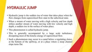


![TYPES OF STILLING BASINS
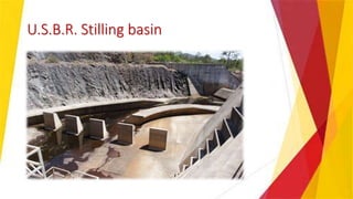
• [A] U.S.B.R. Stilling basin
1. Type – 1 Basin
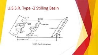
2. Type – 2 Basin
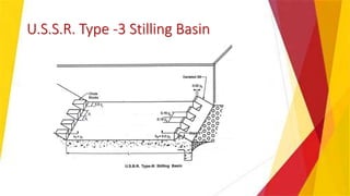
3. Type – 3 Basin
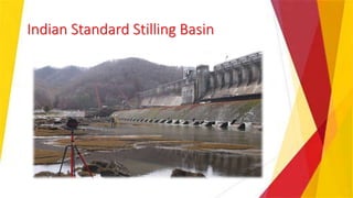
• [B] Indian Standard Basin
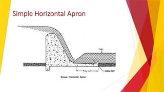
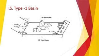
1. Horizontal Apron Type -1
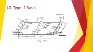
2. Horizontal Apron Type -2
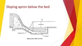
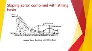
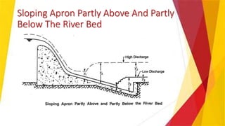
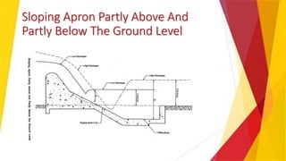
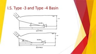
3. Sloping Apron Type -3
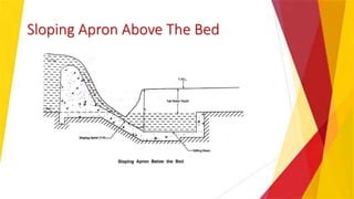
4. Sloping Apron Type -4](https://image.slidesharecdn.com/energydissipation-irrigationengineering-171016085809/85/Energy-dissipation-irrigation-engineering-25-320.jpg)


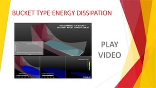

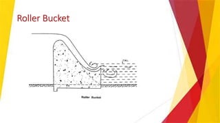
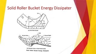


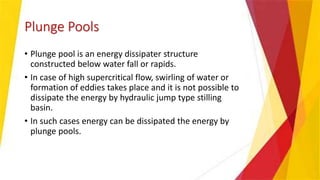


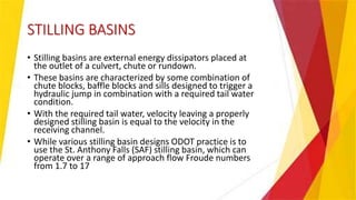
This document discusses various methods of energy dissipation in irrigation engineering, focusing on concepts such as hydraulic jumps, stilling basins, and bucket-type energy dissipators. It explains the significance of controlling kinetic energy in water flows to prevent damage to spillways and river beds, detailing the mechanics of hydraulic jumps and the design of stilling basins. Plunge pools are also addressed as energy dissipaters used under specific conditions, emphasizing their construction and scour risks.