DEPARTMENT OF MECHANICALENGINEERING
COURSE OBJETIVES
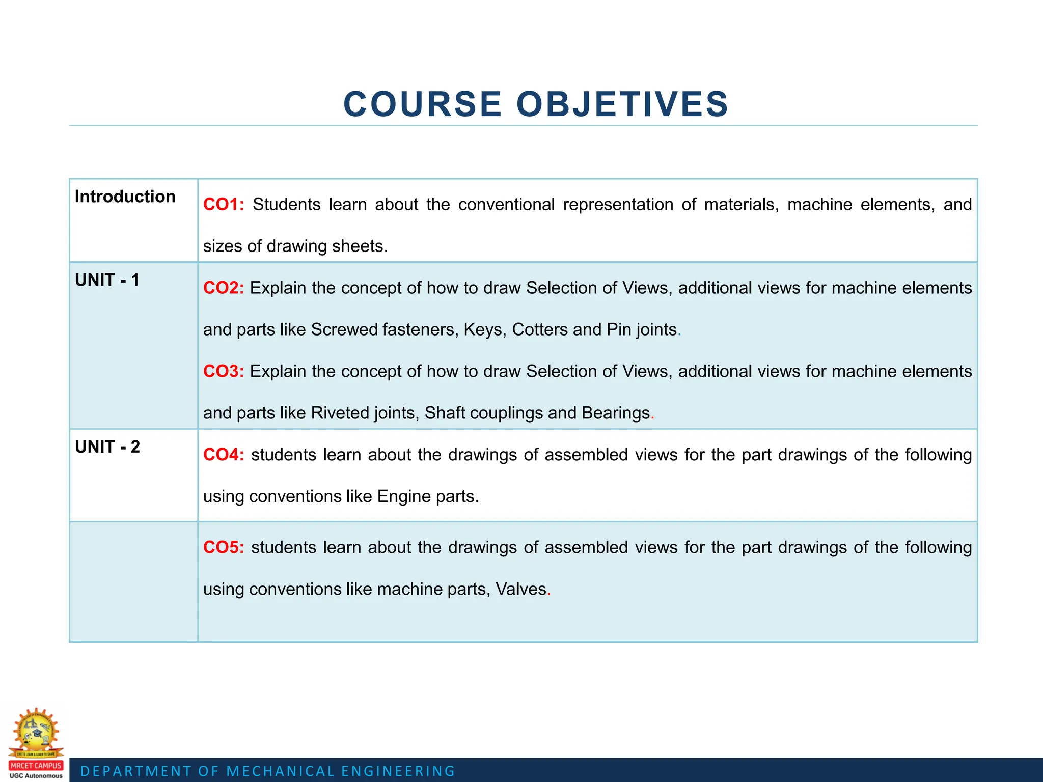
Introduction CO1: Students learn about the conventional representation of materials, machine elements, and
sizes of drawing sheets.
UNIT - 1 CO2: Explain the concept of how to draw Selection of Views, additional views for machine elements
and parts like Screwed fasteners, Keys, Cotters and Pin joints.
CO3: Explain the concept of how to draw Selection of Views, additional views for machine elements
and parts like Riveted joints, Shaft couplings and Bearings.
UNIT - 2 CO4: students learn about the drawings of assembled views for the part drawings of the following
using conventions like Engine parts.
CO5: students learn about the drawings of assembled views for the part drawings of the following
using conventions like machine parts, Valves.
DEPARTMENT OF MECHANICALENGINEERING
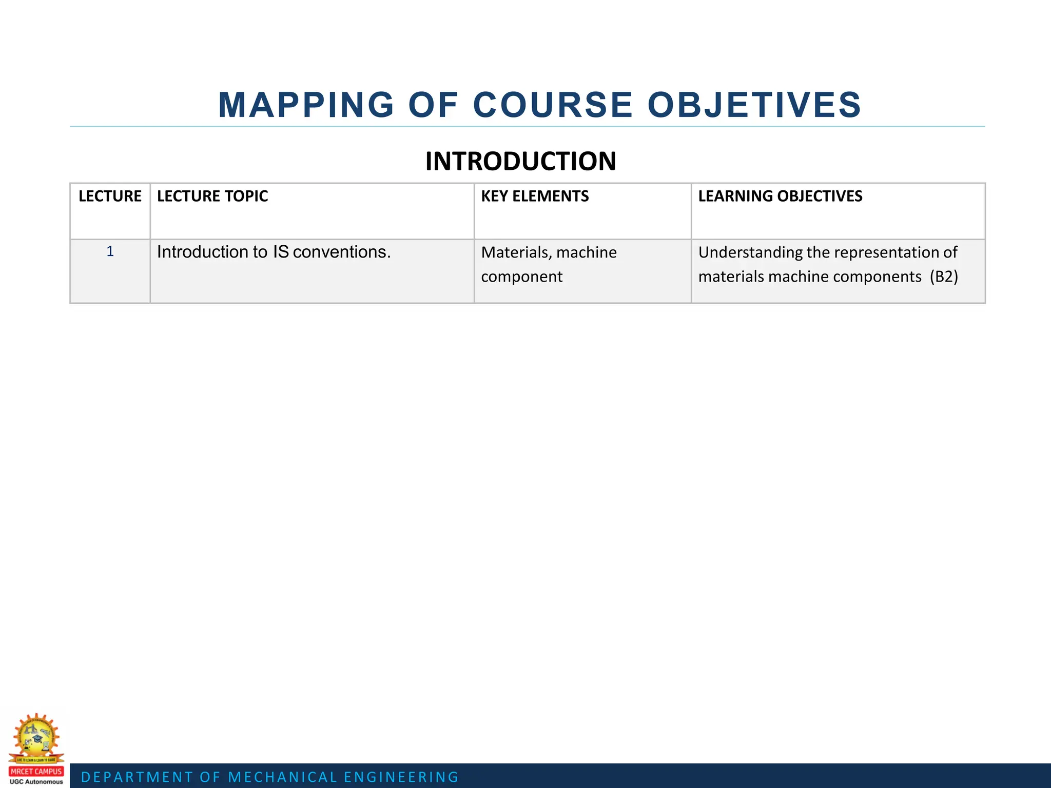
MAPPING OF COURSE OBJETIVES
LECTURE LECTURE TOPIC KEY ELEMENTS LEARNING OBJECTIVES
1 Introduction to IS conventions. Materials, machine
component
Understanding the representation of
materials machine components (B2)
INTRODUCTION
5.
DEPARTMENT OF MECHANICALENGINEERING
INTRODUCTION SYLLABUS
MACHINE DRAWING CONVENTIONS
• Need for drawing conventions –Introduction to IS conventions.
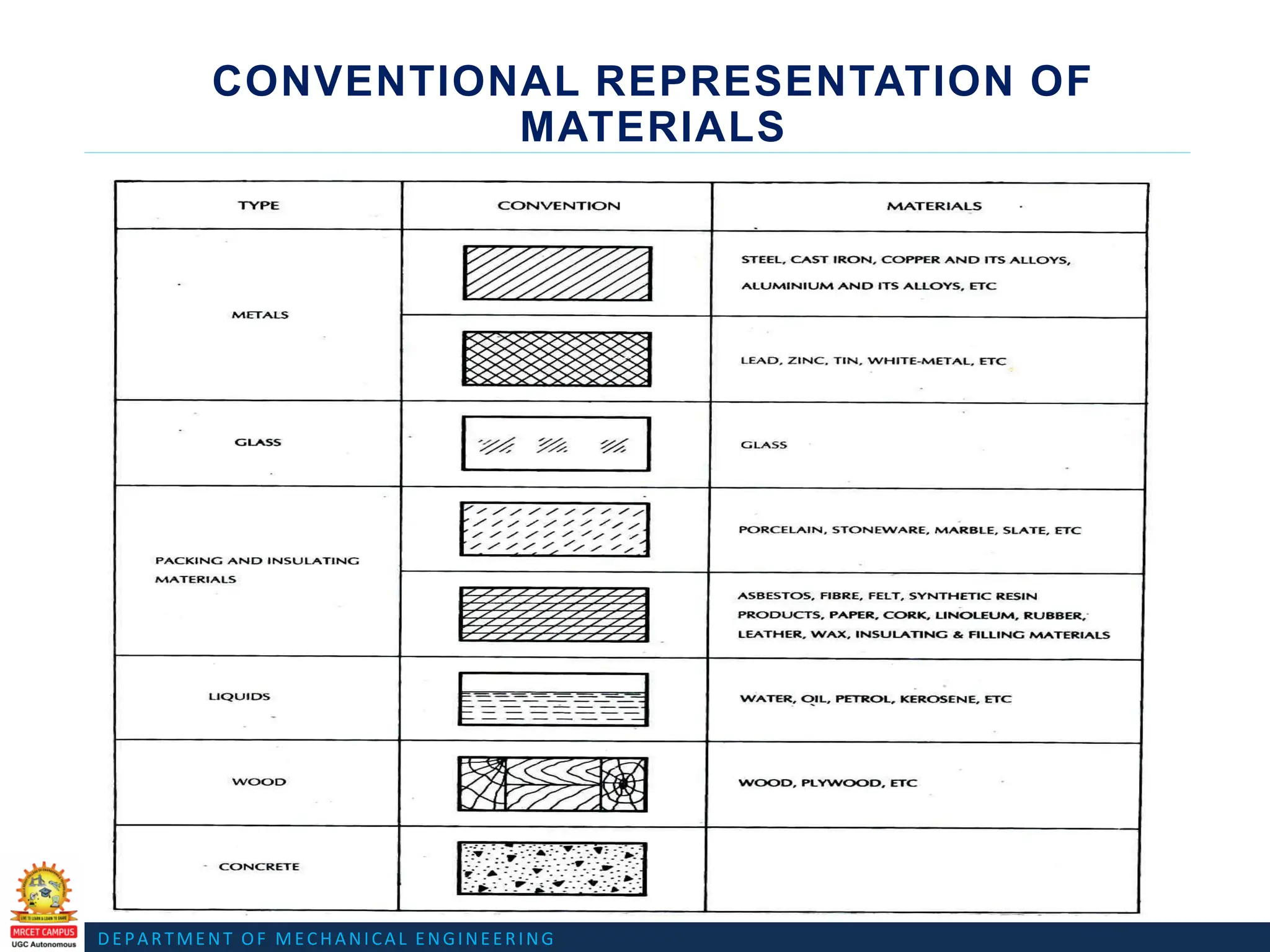
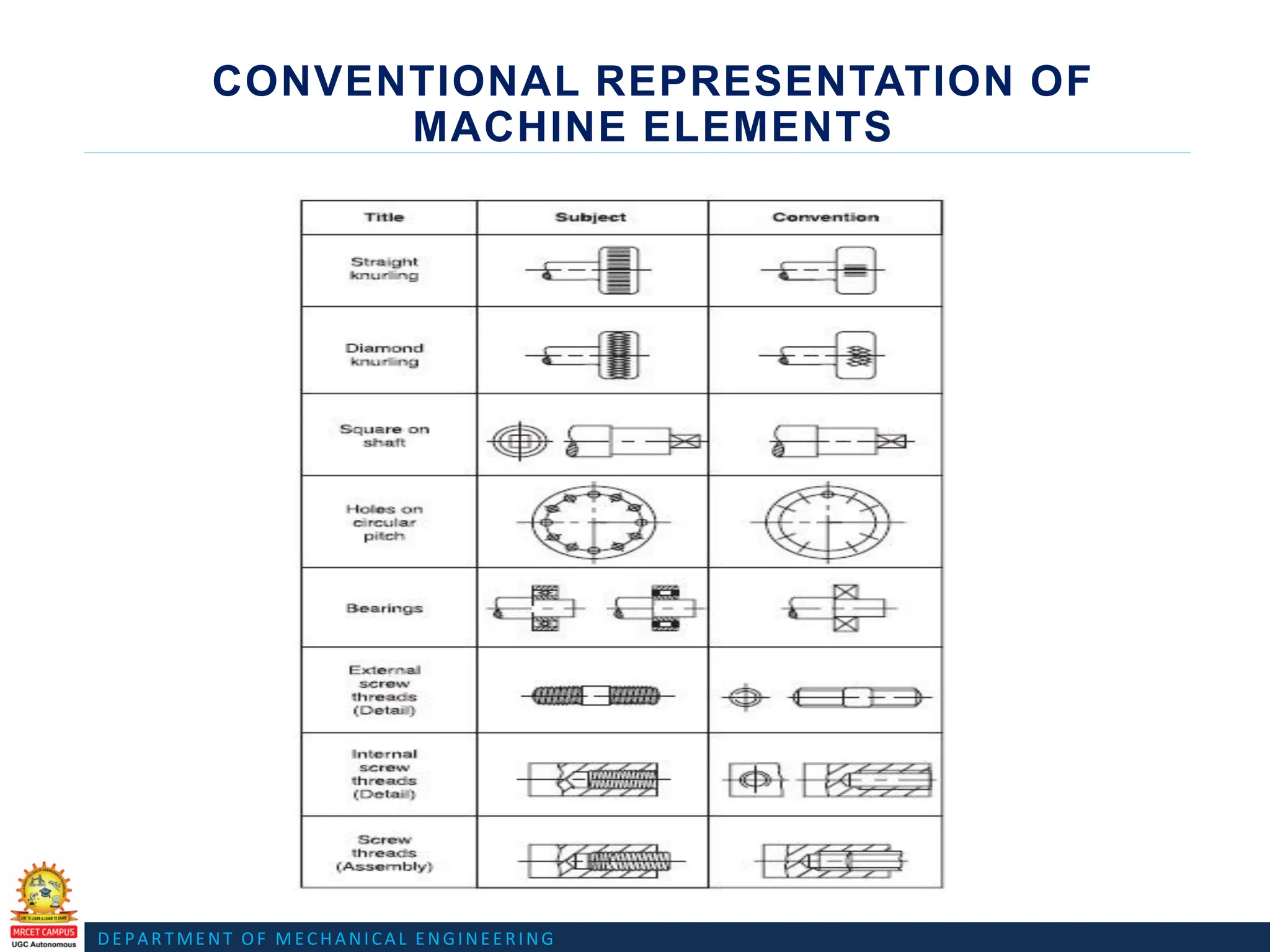
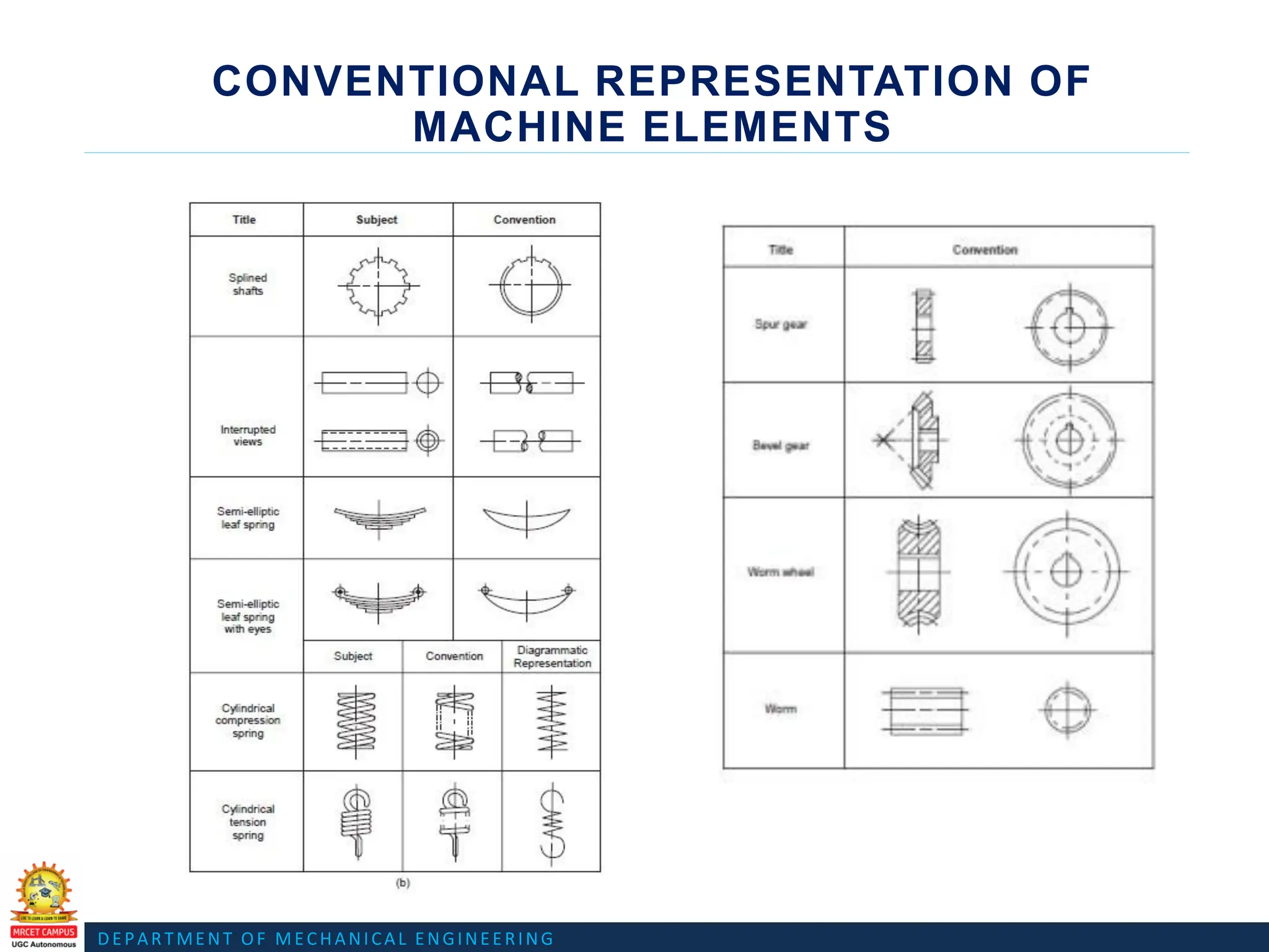
• Conventional representation of materials, common machine
elements and parts such as screws, nuts, bolts, keys, gears.
• Methods of dimensioning, general rules for sizes and placement of
dimensions for holes, canters curved and tapered features.
• Title boxes, their size, location and details -common abbreviations
& their liberal usage
• Types of Drawings –working drawings for machine parts.
DEPARTMENT OF MECHANICALENGINEERING
S C R E W E S F A S T E N E R S , K E Y S , C O T T E R S , P I N J O I N T S ,
R I V E T E D J O I N T S , S H A F T C O U P L I N S A N D B E A R I N G S
U N I T - 1
10.
DEPARTMENT OF MECHANICALENGINEERING
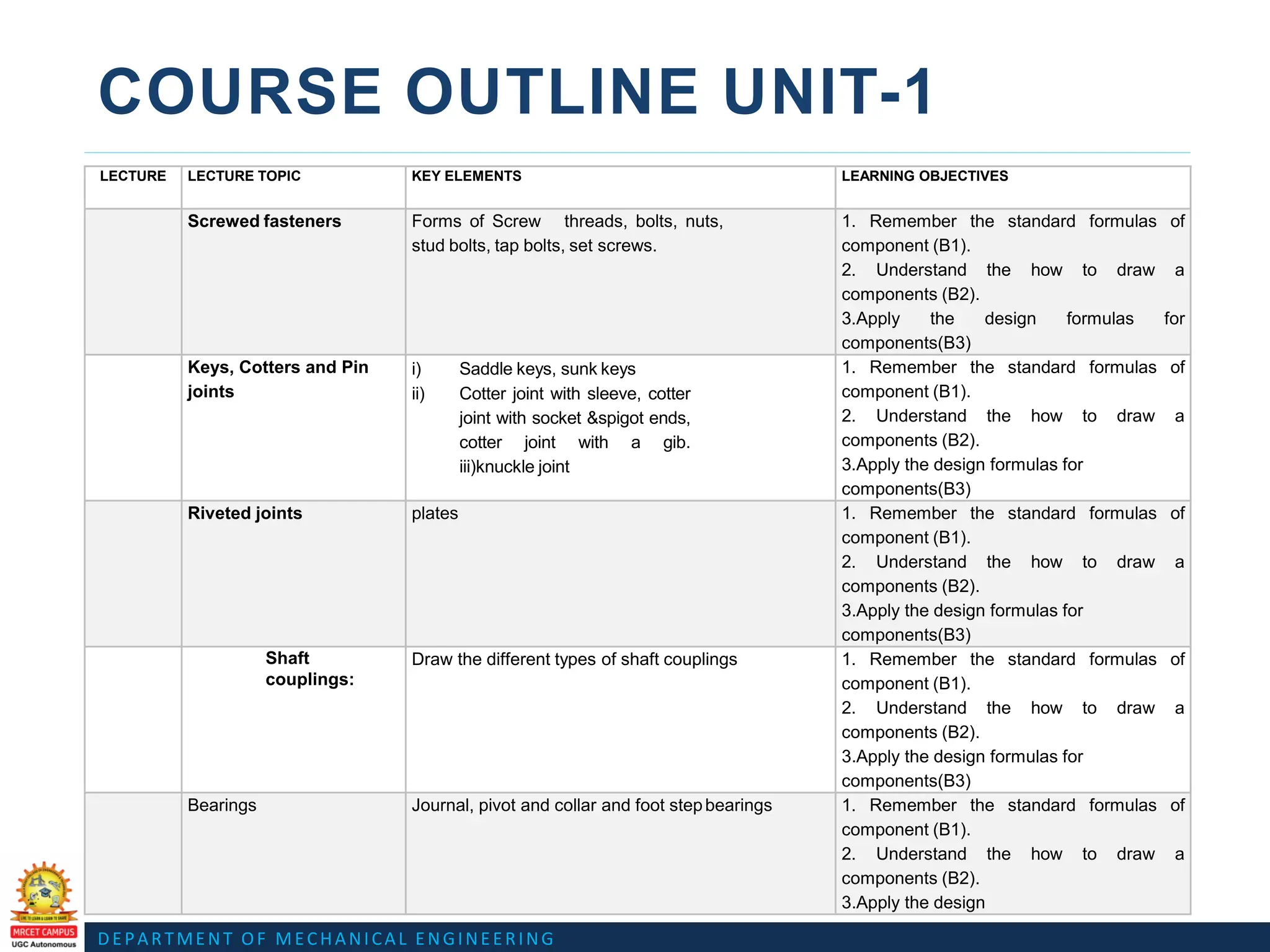
COURSE OUTLINE UNIT-1
LECTURE LECTURE TOPIC KEY ELEMENTS LEARNING OBJECTIVES
Screwed fasteners Forms of Screw threads, bolts, nuts,
stud bolts, tap bolts, set screws.
1. Remember the standard formulas of
component (B1).
2. Understand the how to draw a
components (B2).
3.Apply the design formulas for
components(B3)
Keys, Cotters and Pin
joints
i) Saddle keys, sunk keys
ii) Cotter joint with sleeve, cotter
joint with socket &spigot ends,
cotter joint with a gib.
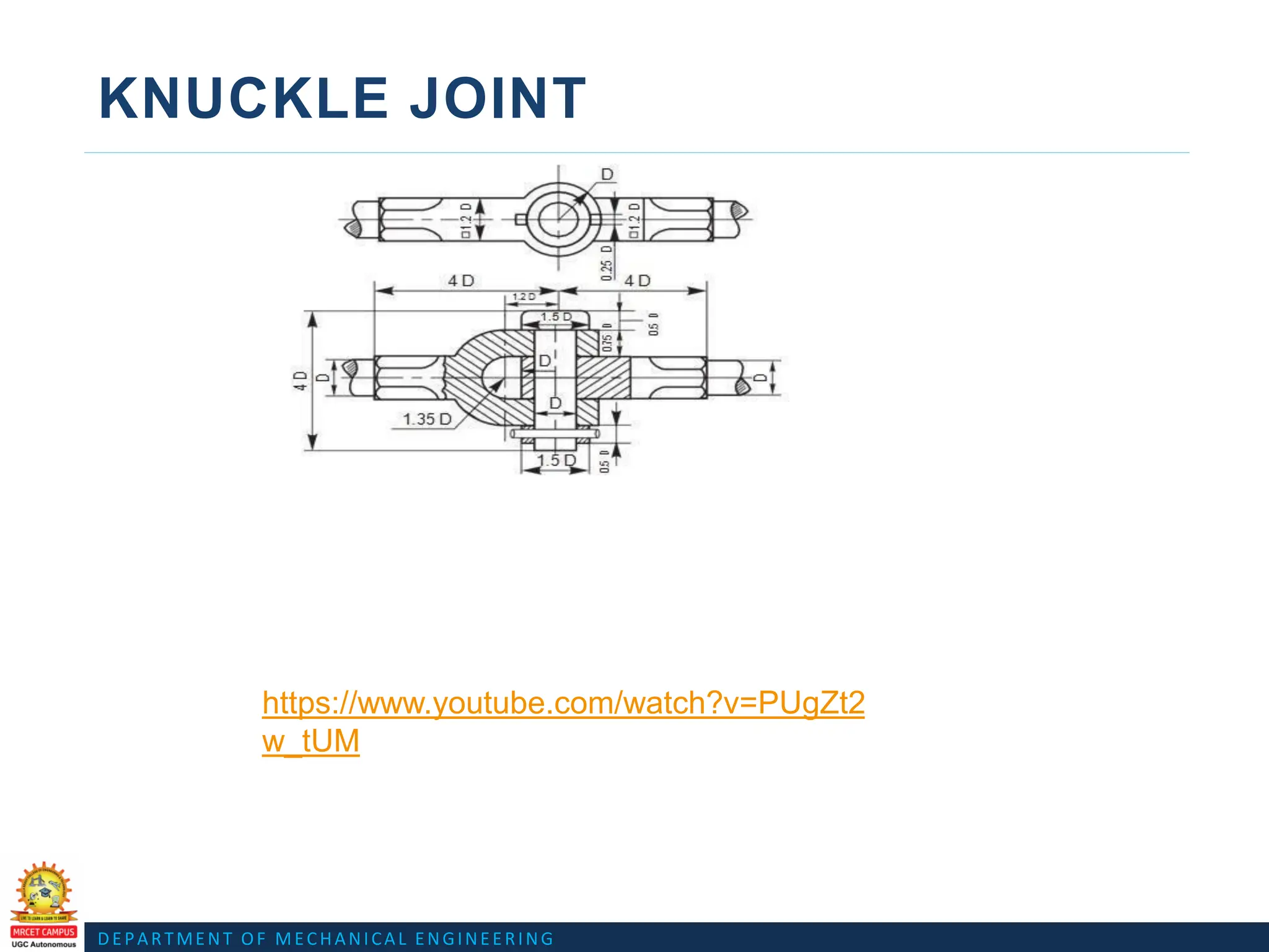
iii)knuckle joint
1. Remember the standard formulas of
component (B1).
2. Understand the how to draw a
components (B2).
3.Apply the design formulas for
components(B3)
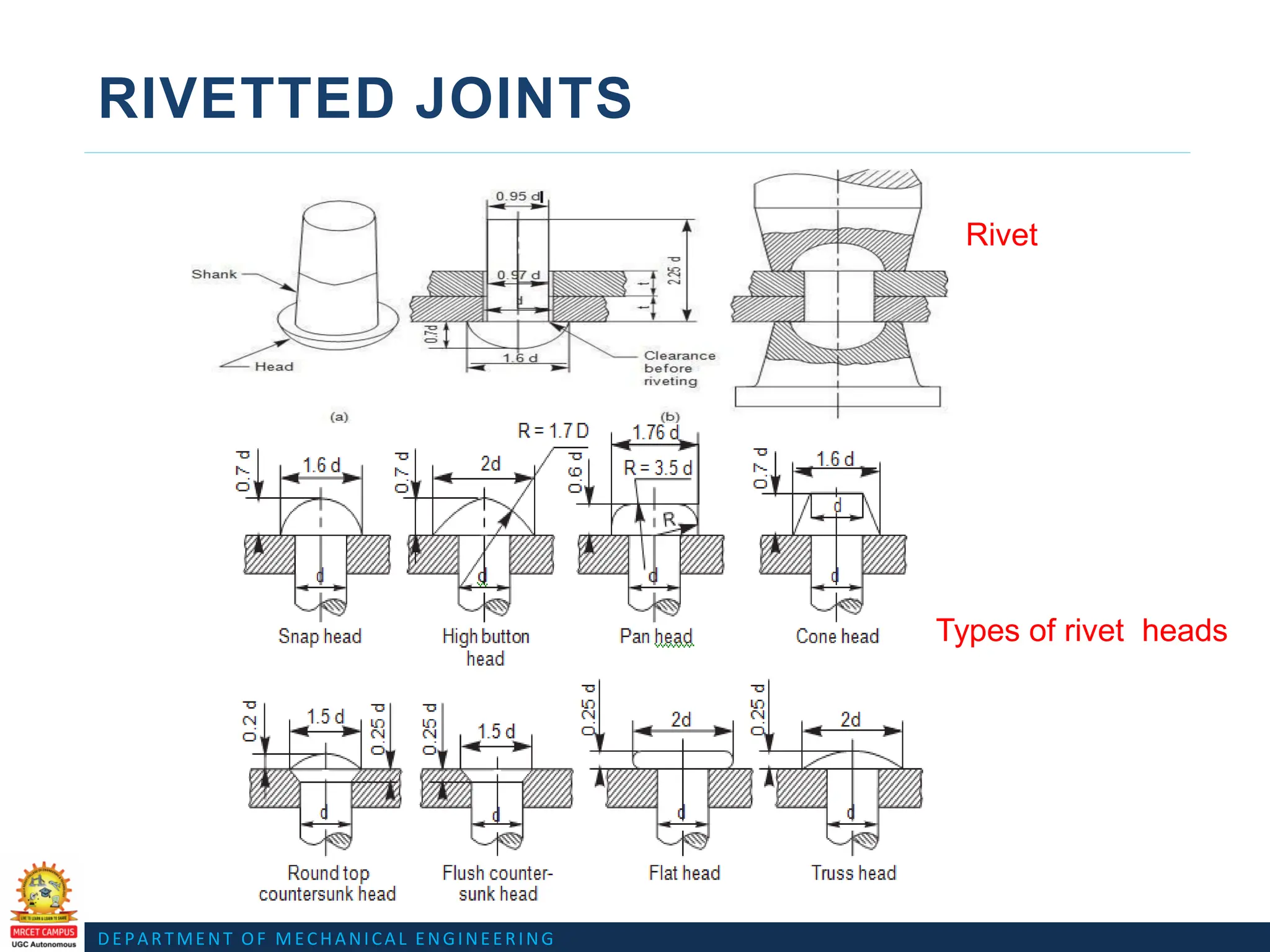
Riveted joints plates 1. Remember the standard formulas of
component (B1).
2. Understand the how to draw a
components (B2).
3.Apply the design formulas for
components(B3)
Shaft
couplings:
Draw the different types of shaft couplings 1. Remember the standard formulas of
component (B1).
2. Understand the how to draw a
components (B2).
3.Apply the design formulas for
components(B3)
Bearings Journal, pivot and collar and foot stepbearings 1. Remember the standard formulas of
component (B1).
2. Understand the how to draw a
components (B2).
3.Apply the design
11.
DEPARTMENT OF MECHANICALENGINEERING
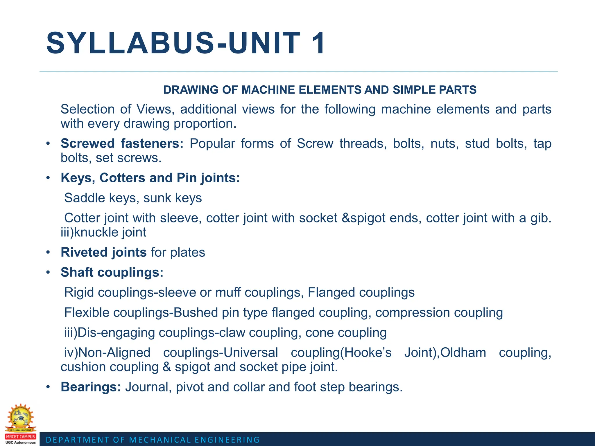
SYLLABUS-UNIT 1
DRAWING OF MACHINE ELEMENTS AND SIMPLE PARTS
Selection of Views, additional views for the following machine elements and parts
with every drawing proportion.
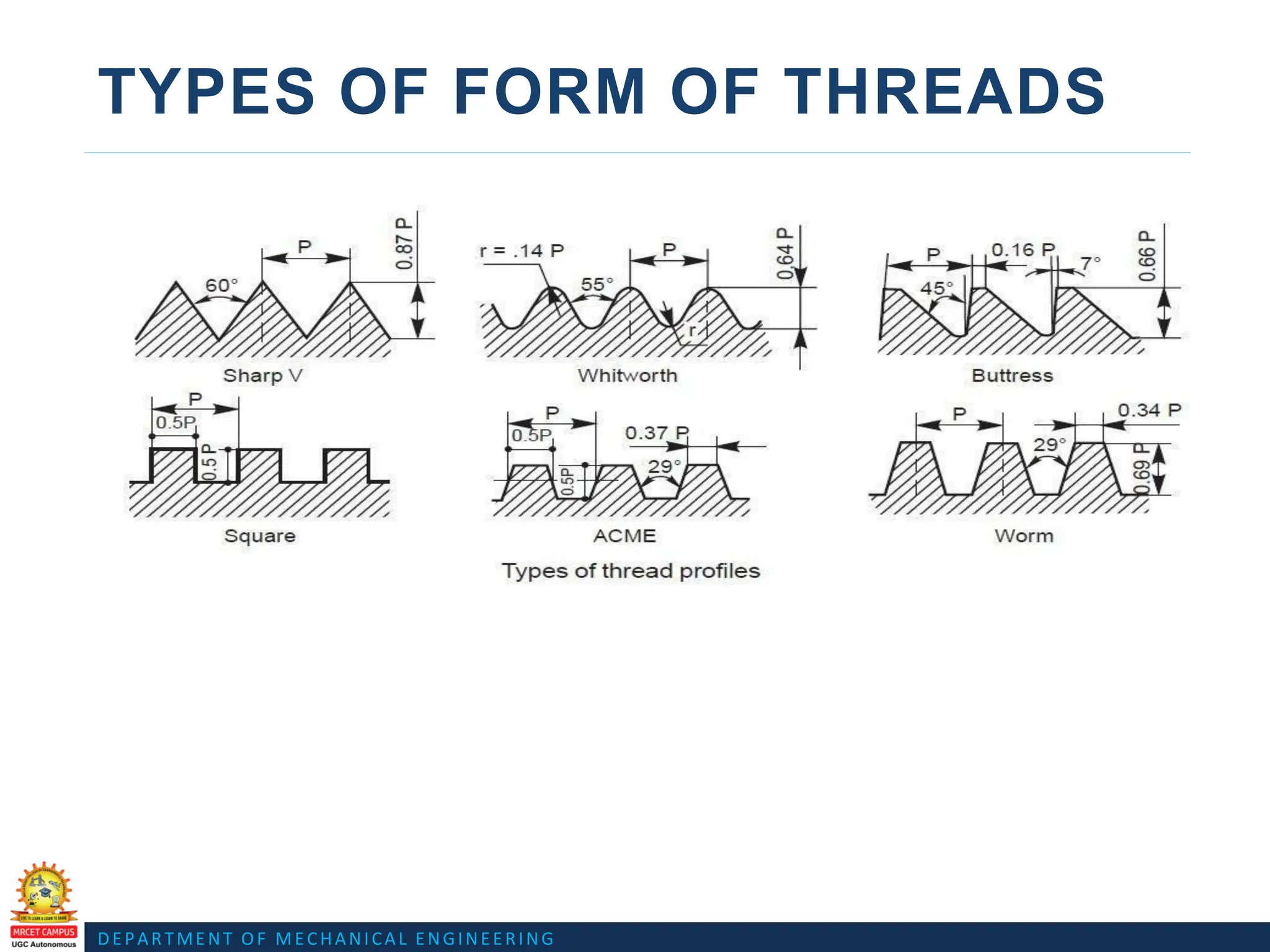
• Screwed fasteners: Popular forms of Screw threads, bolts, nuts, stud bolts, tap
bolts, set screws.
• Keys, Cotters and Pin joints:
Saddle keys, sunk keys
Cotter joint with sleeve, cotter joint with socket &spigot ends, cotter joint with a gib.
iii)knuckle joint
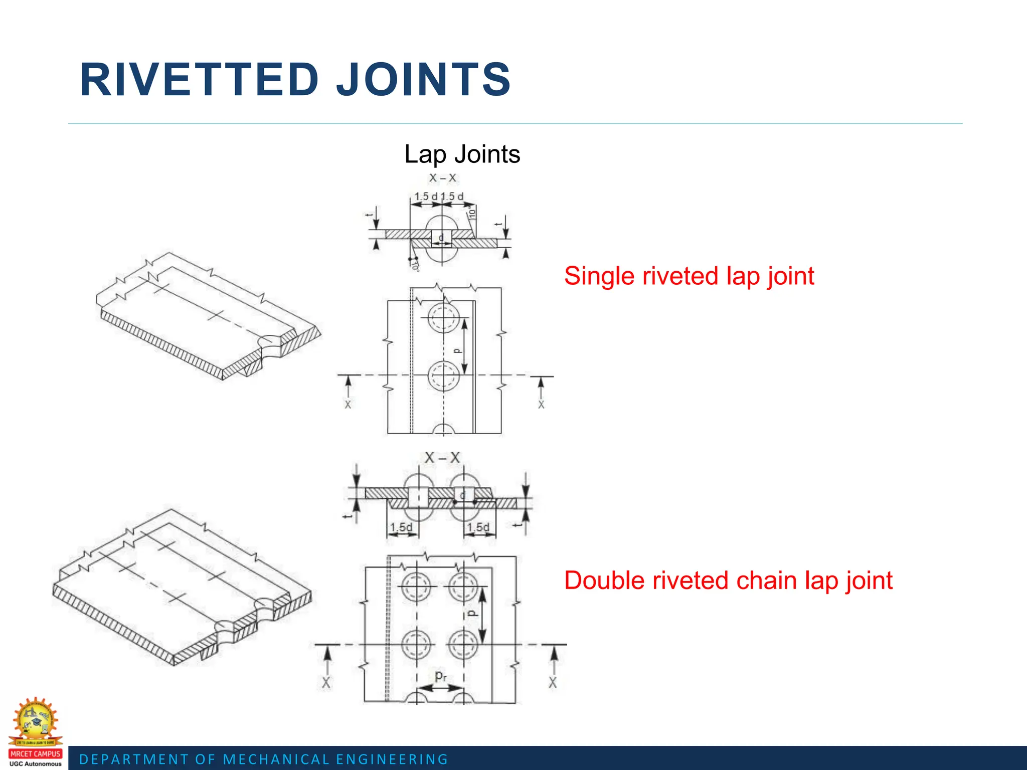
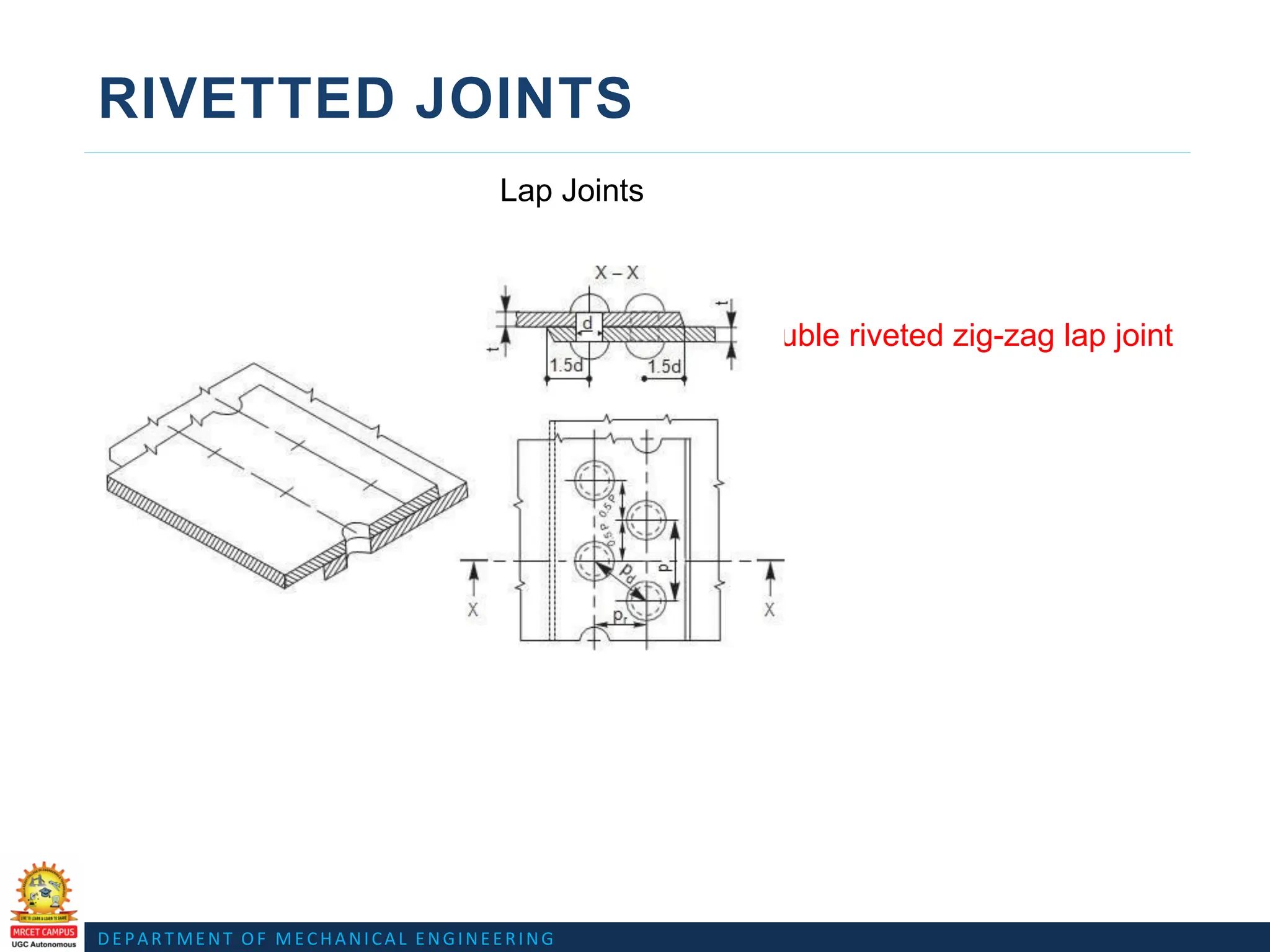
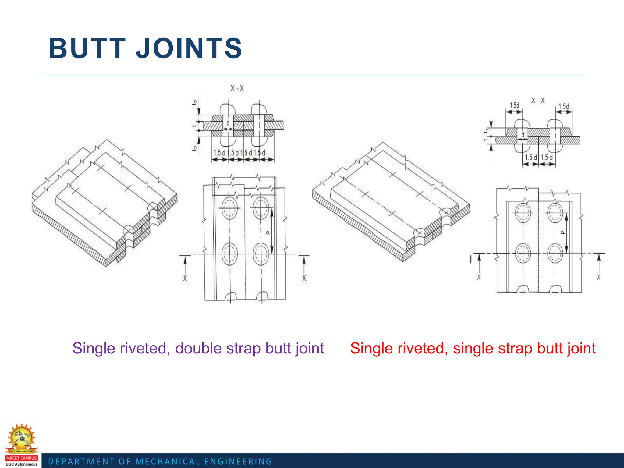
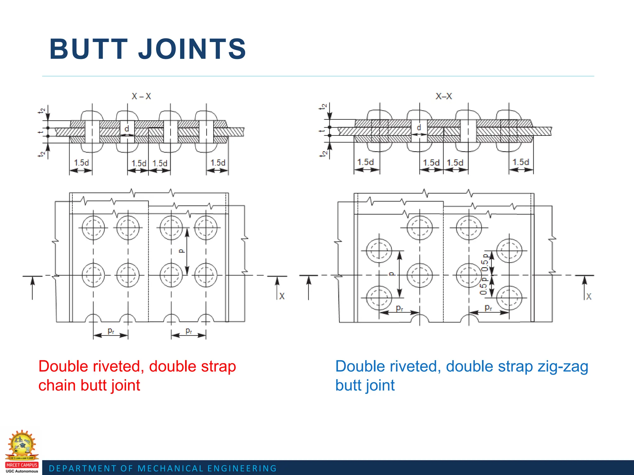
• Riveted joints for plates
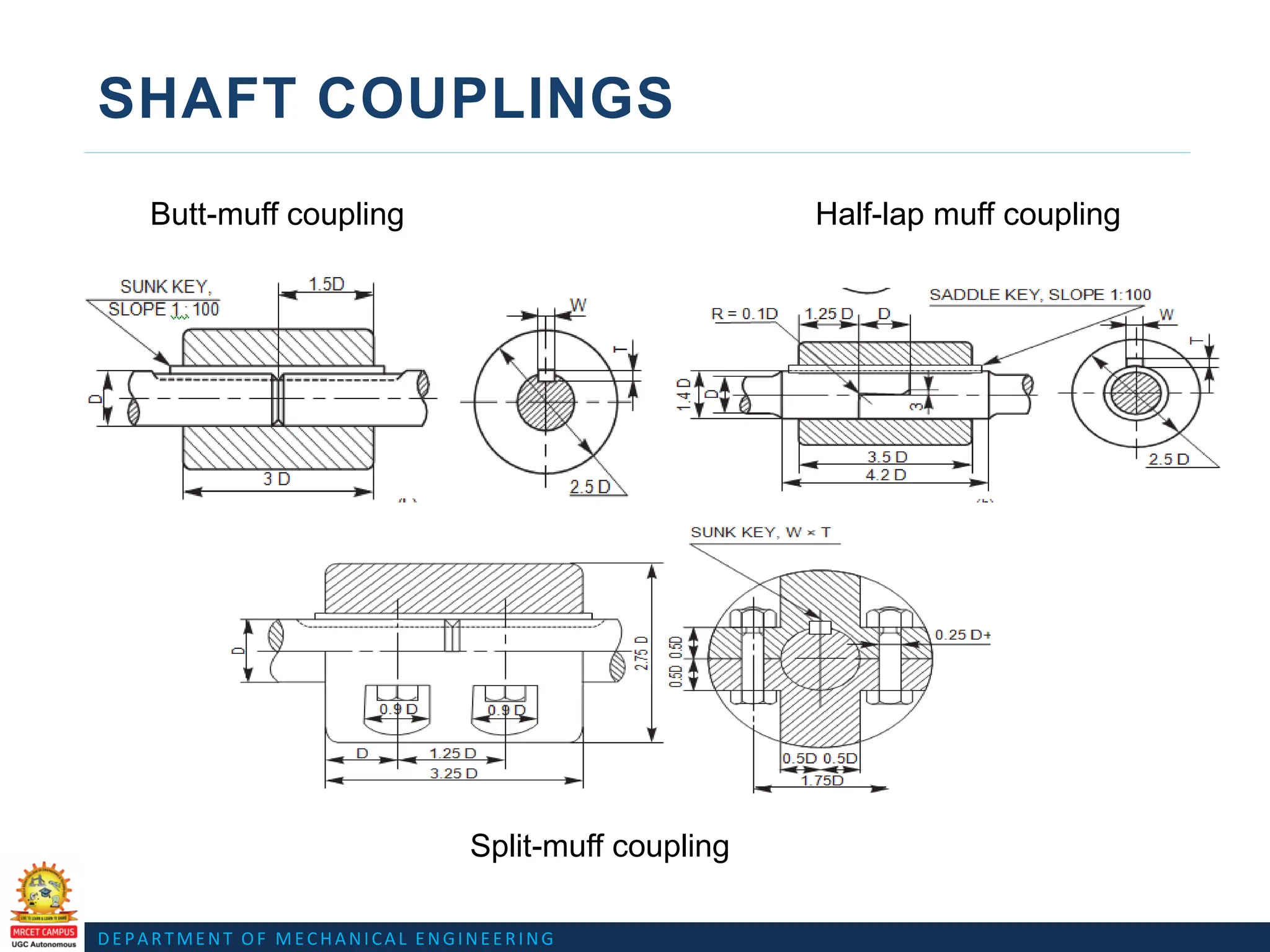
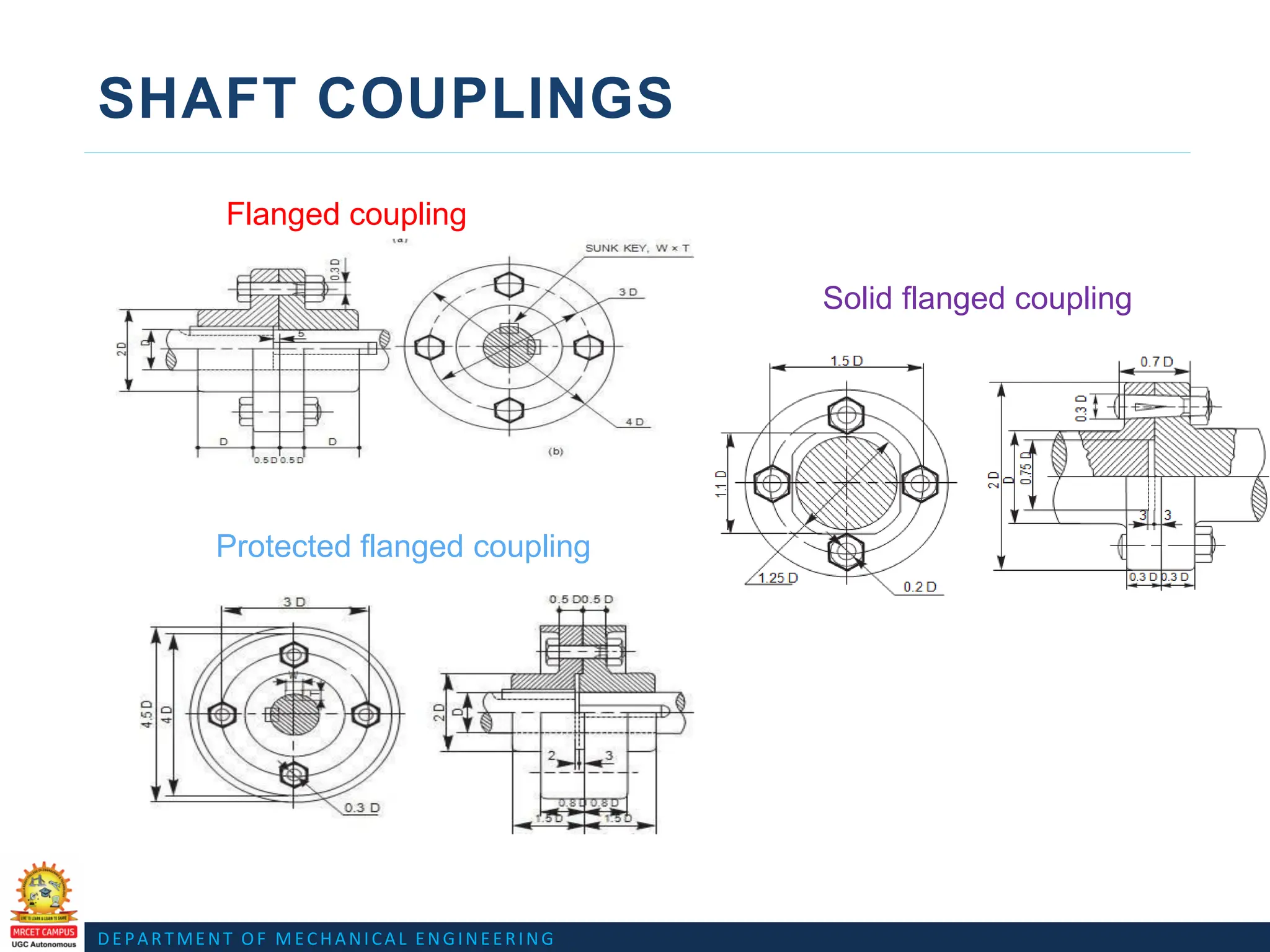
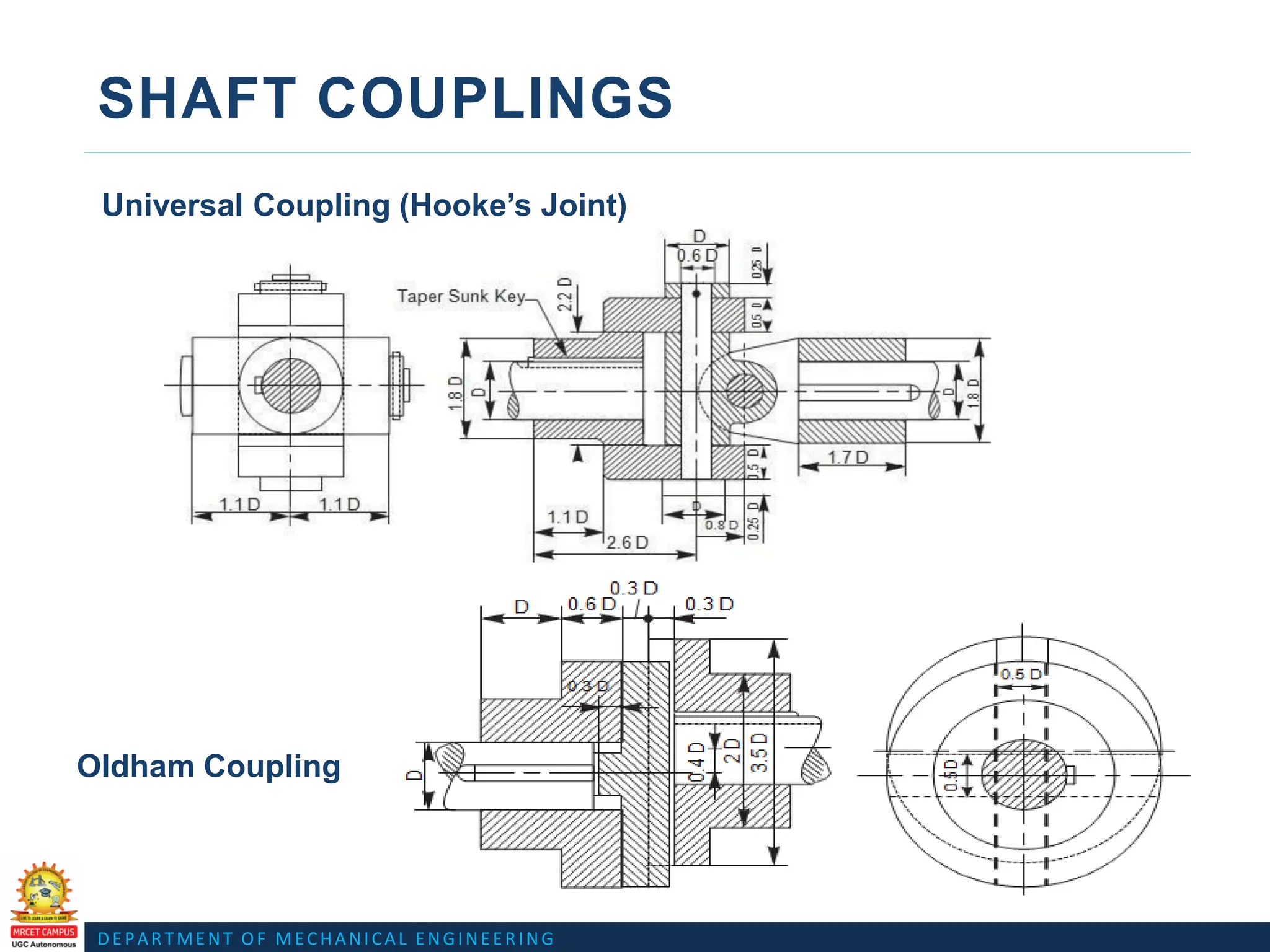
• Shaft couplings:
Rigid couplings-sleeve or muff couplings, Flanged couplings
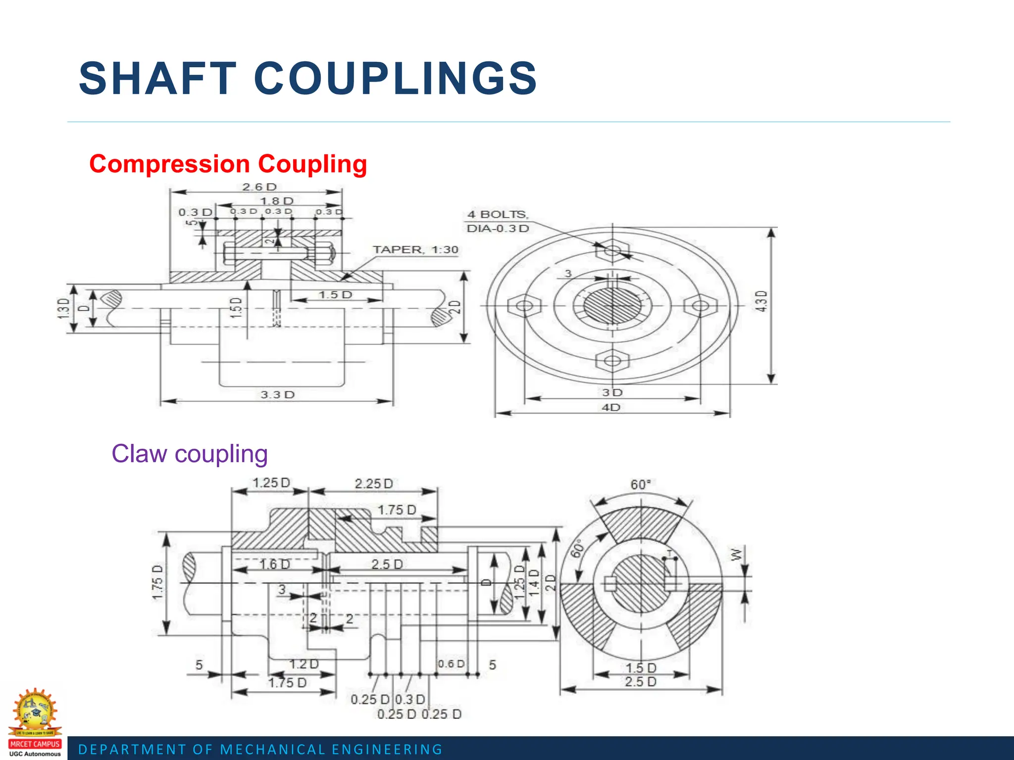
Flexible couplings-Bushed pin type flanged coupling, compression coupling
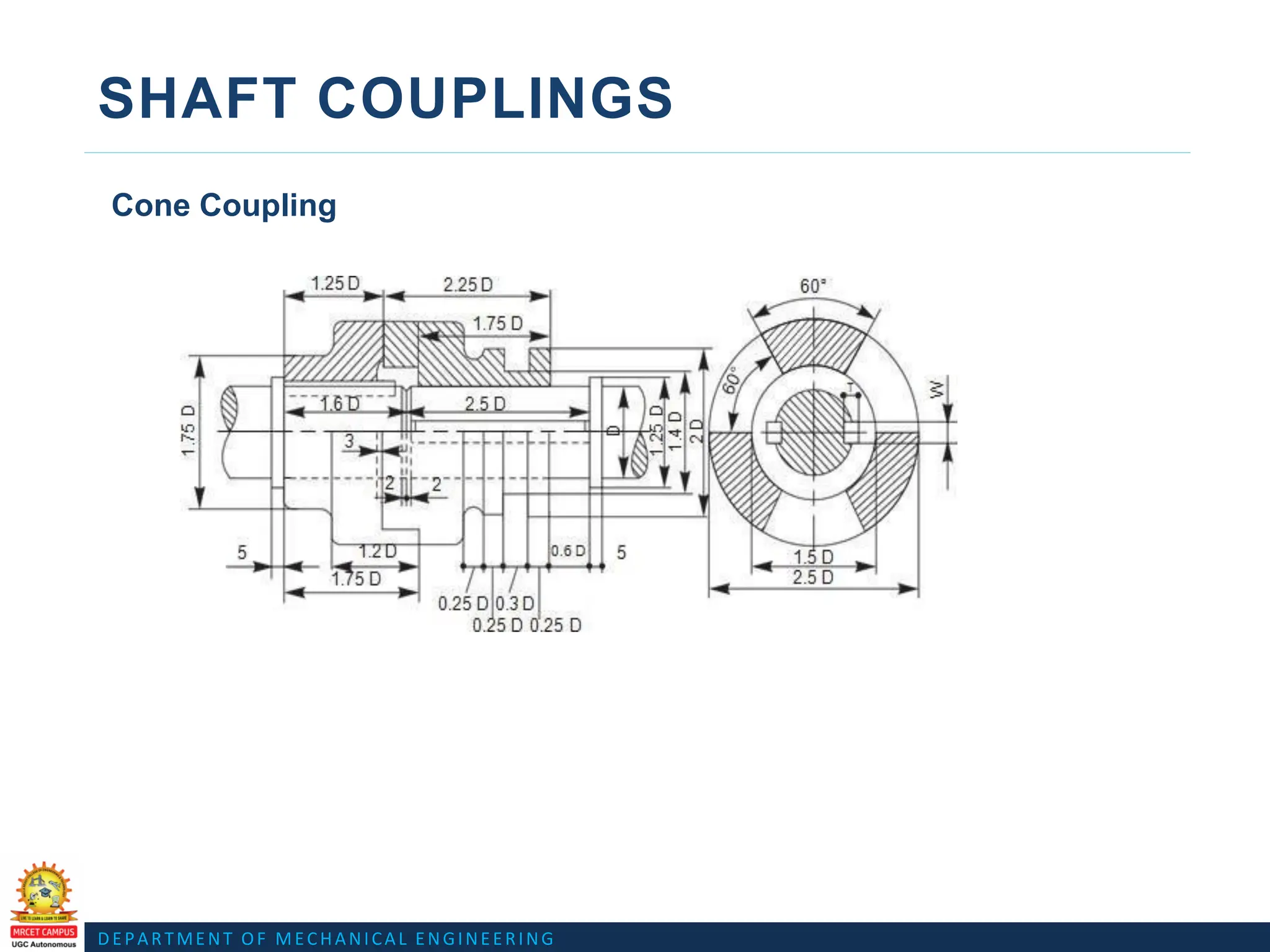
iii)Dis-engaging couplings-claw coupling, cone coupling
iv)Non-Aligned couplings-Universal coupling(Hooke’s Joint),Oldham coupling,
cushion coupling & spigot and socket pipe joint.
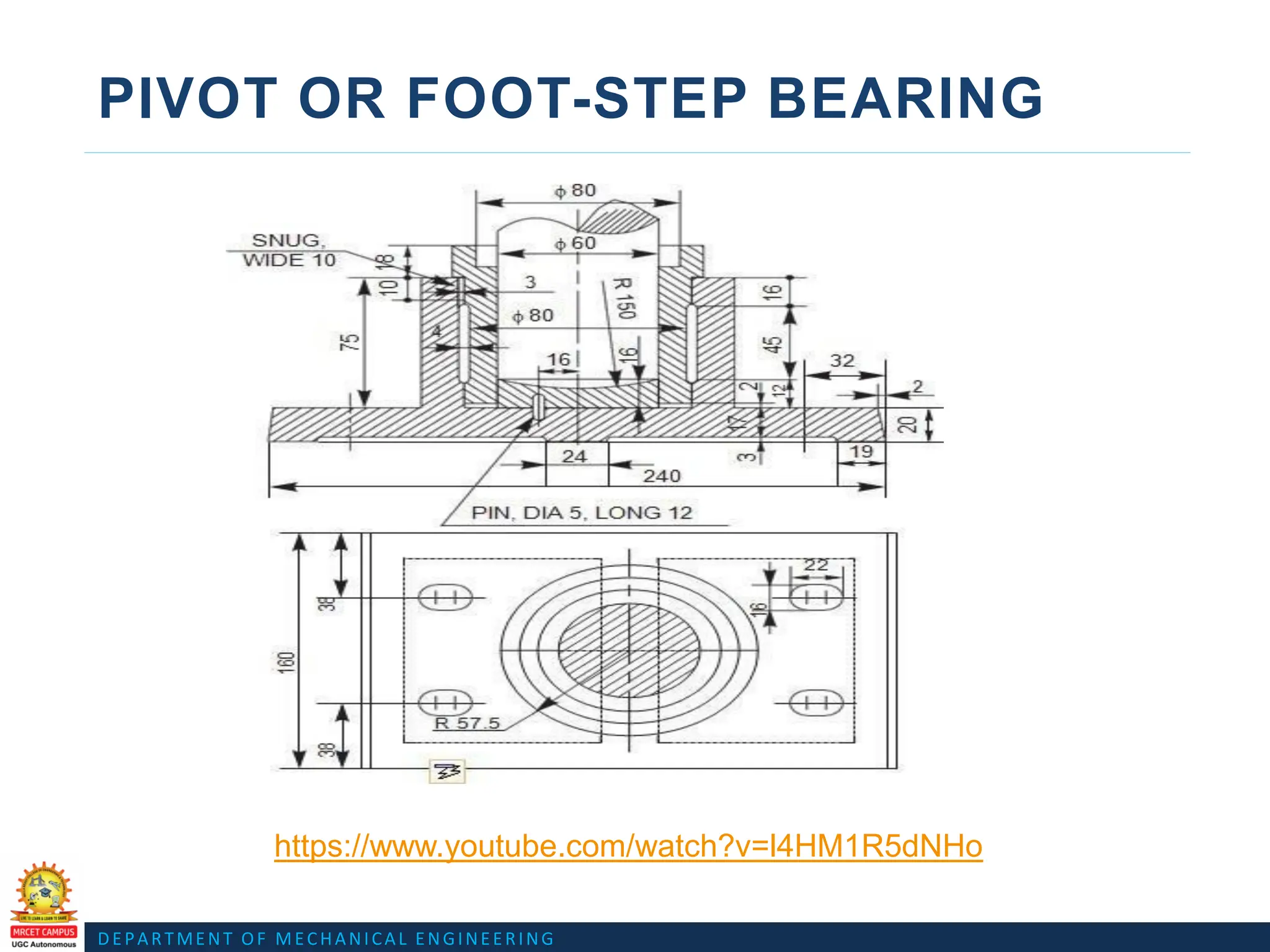
• Bearings: Journal, pivot and collar and foot step bearings.
DEPARTMENT OF MECHANICALENGINEERING
BOLTED JOINT
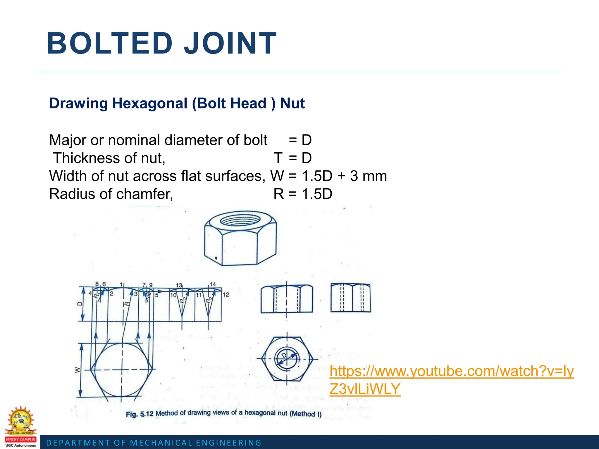
Drawing Hexagonal (Bolt Head ) Nut
Major or nominal diameter of bolt = D
Thickness of nut, T = D
Width of nut across flat surfaces, W = 1.5D + 3 mm
Radius of chamfer, R = 1.5D
https://www.youtube.com/watch?v=ly
Z3vlLiWLY
15.
DEPARTMENT OF MECHANICALENGINEERING
BOLTED JOINT
Drawing Hexagonal (Bolt Head ) Nut
https://www.youtube.com/watch?v=lyZ3vlLiWLY
DEPARTMENT OF MECHANICALENGINEERING
BOLTED JOINT
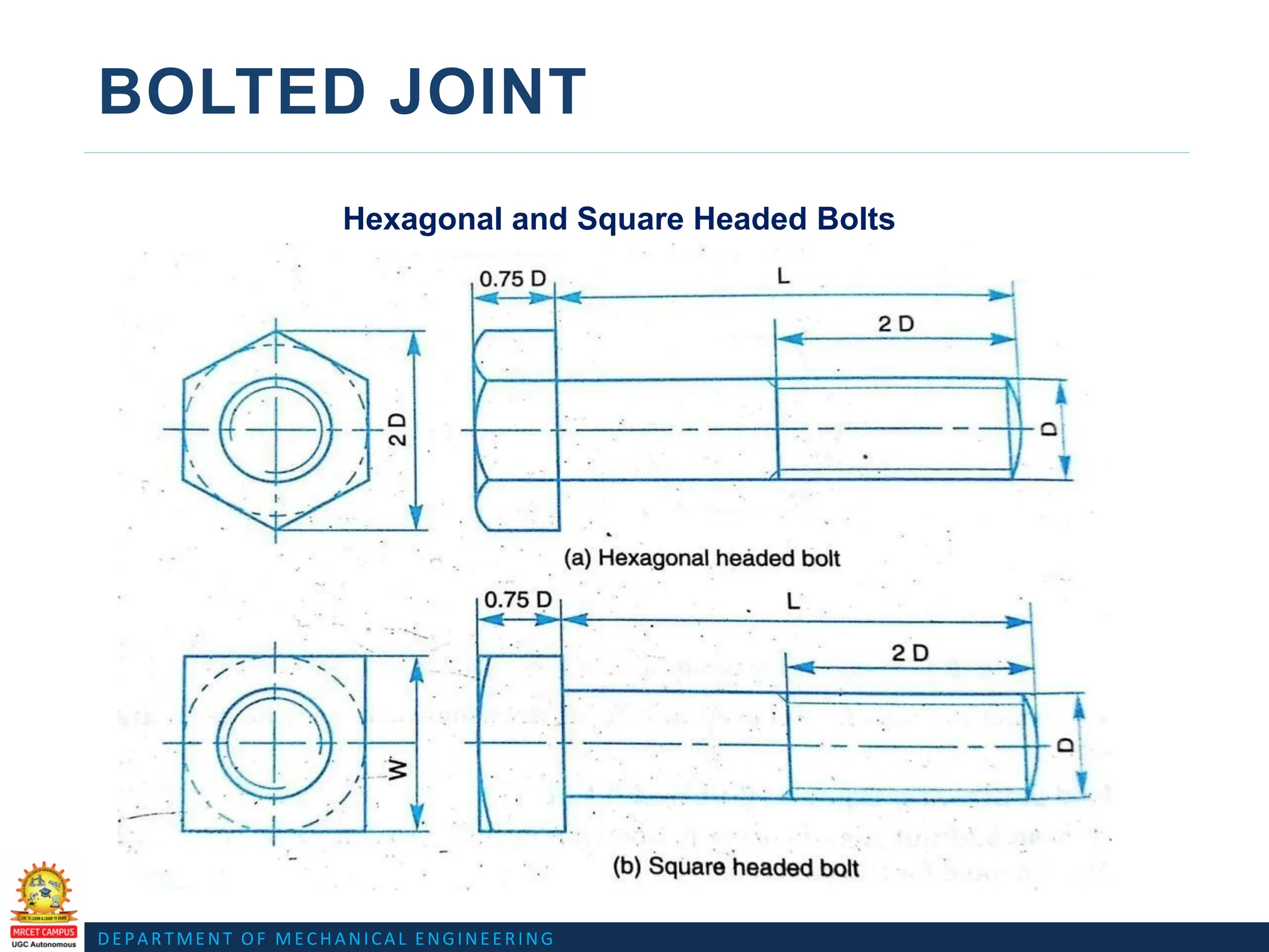
Hexagonal and Square Headed Bolts
https://www.youtube.com/watch?v=FbvBgc9Sq2Y
19.
DEPARTMENT OF MECHANICALENGINEERING
BOLTED JOINT
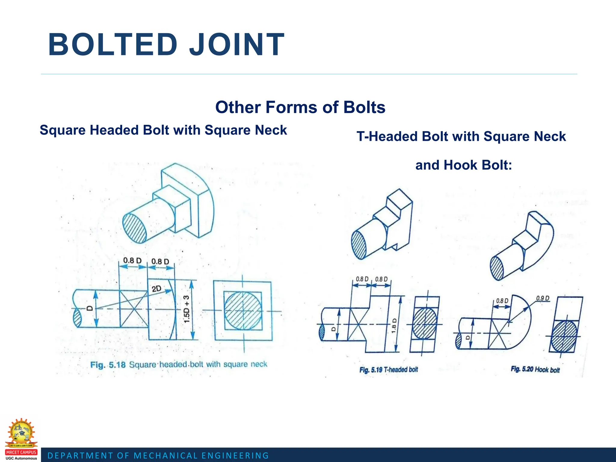
Other Forms of Bolts
Square Headed Bolt with Square Neck
Fig.Square headed bolt with
square neck
T-Headed Bolt with Square Neck
and Hook Bolt:
20.
DEPARTMENT OF MECHANICALENGINEERING
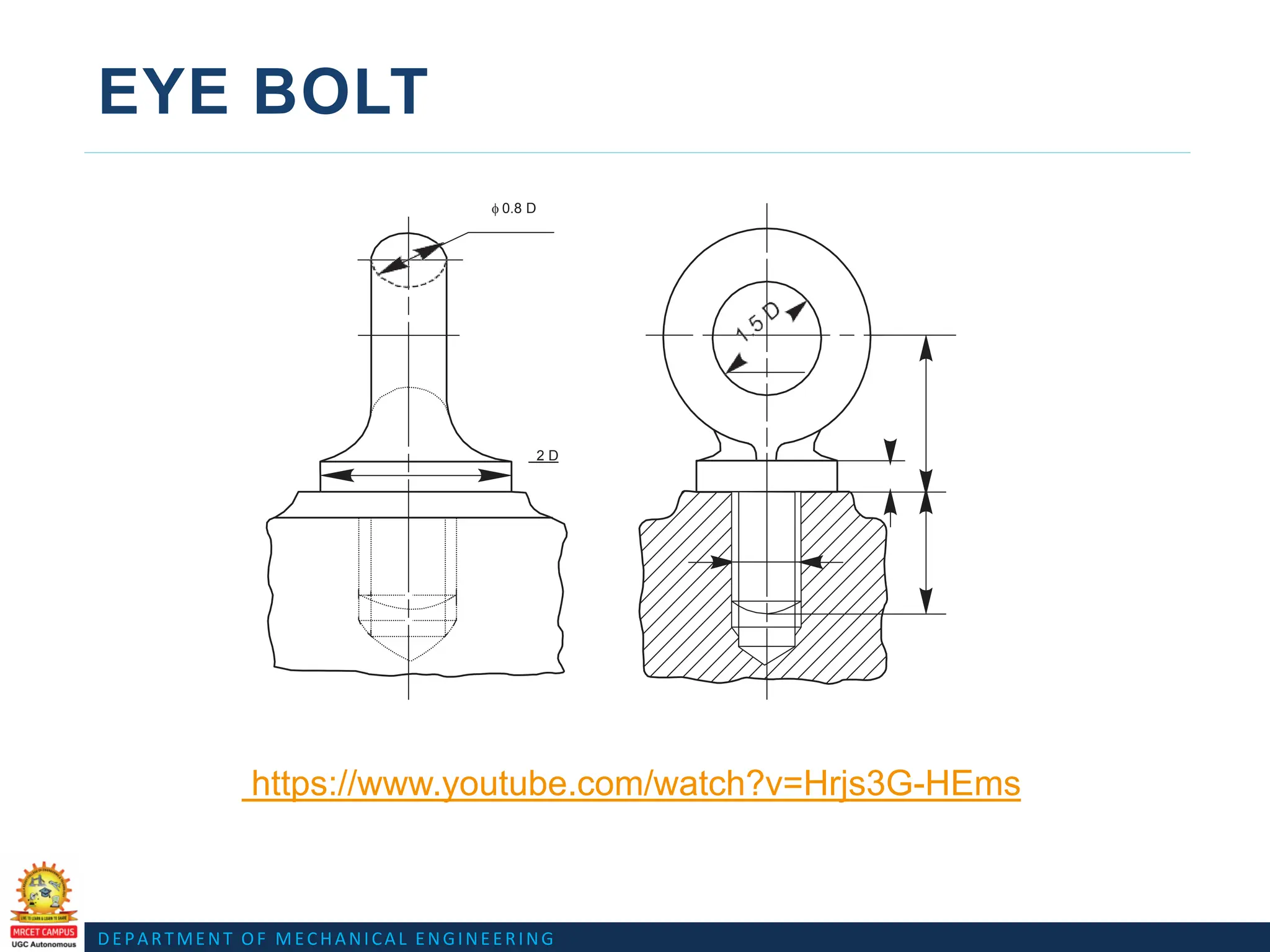
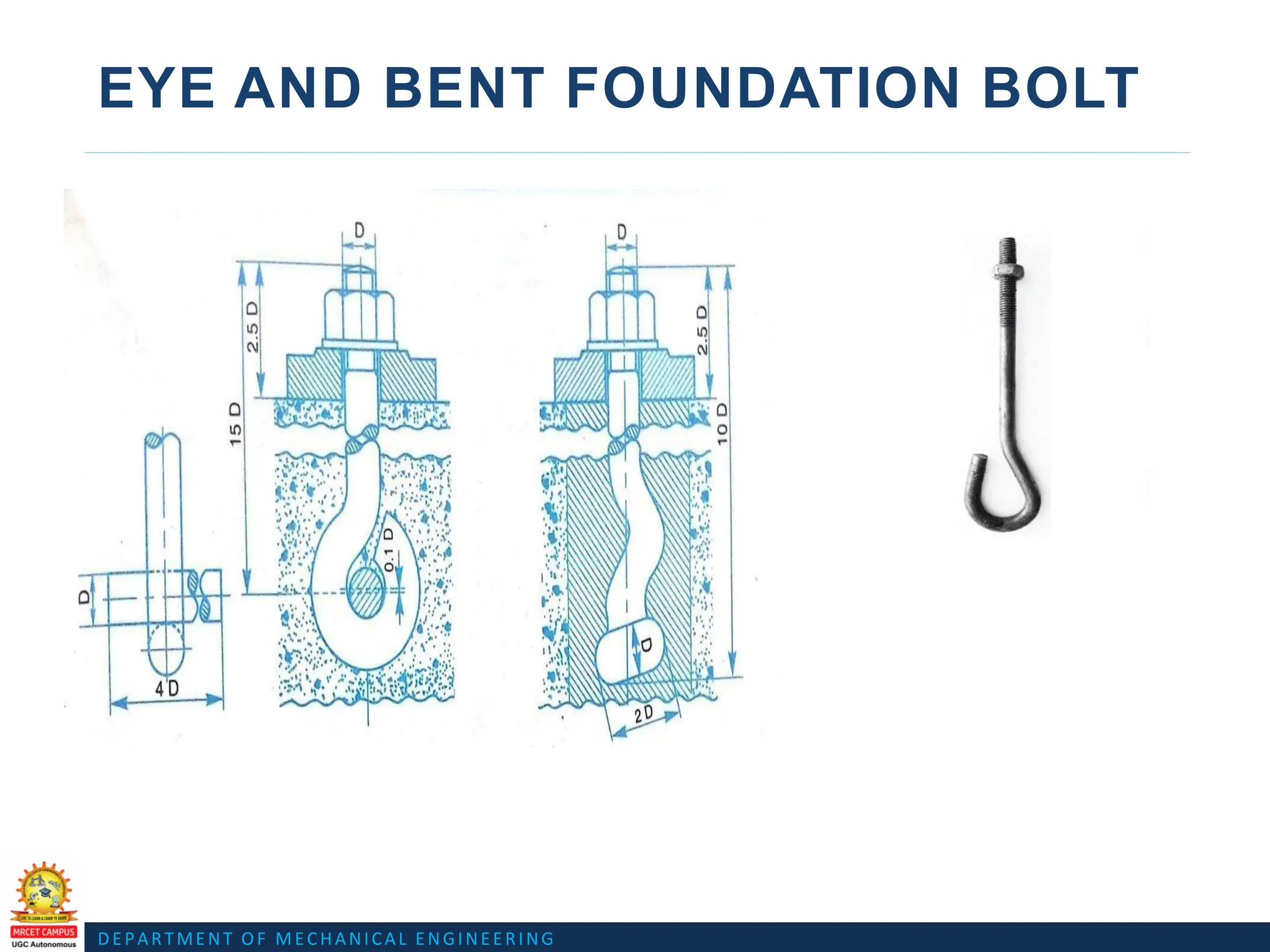
EYE BOLT
f 0.8 D
2 D
https://www.youtube.com/watch?v=Hrjs3G-HEms
DEPARTMENT OF MECHANICALENGINEERING
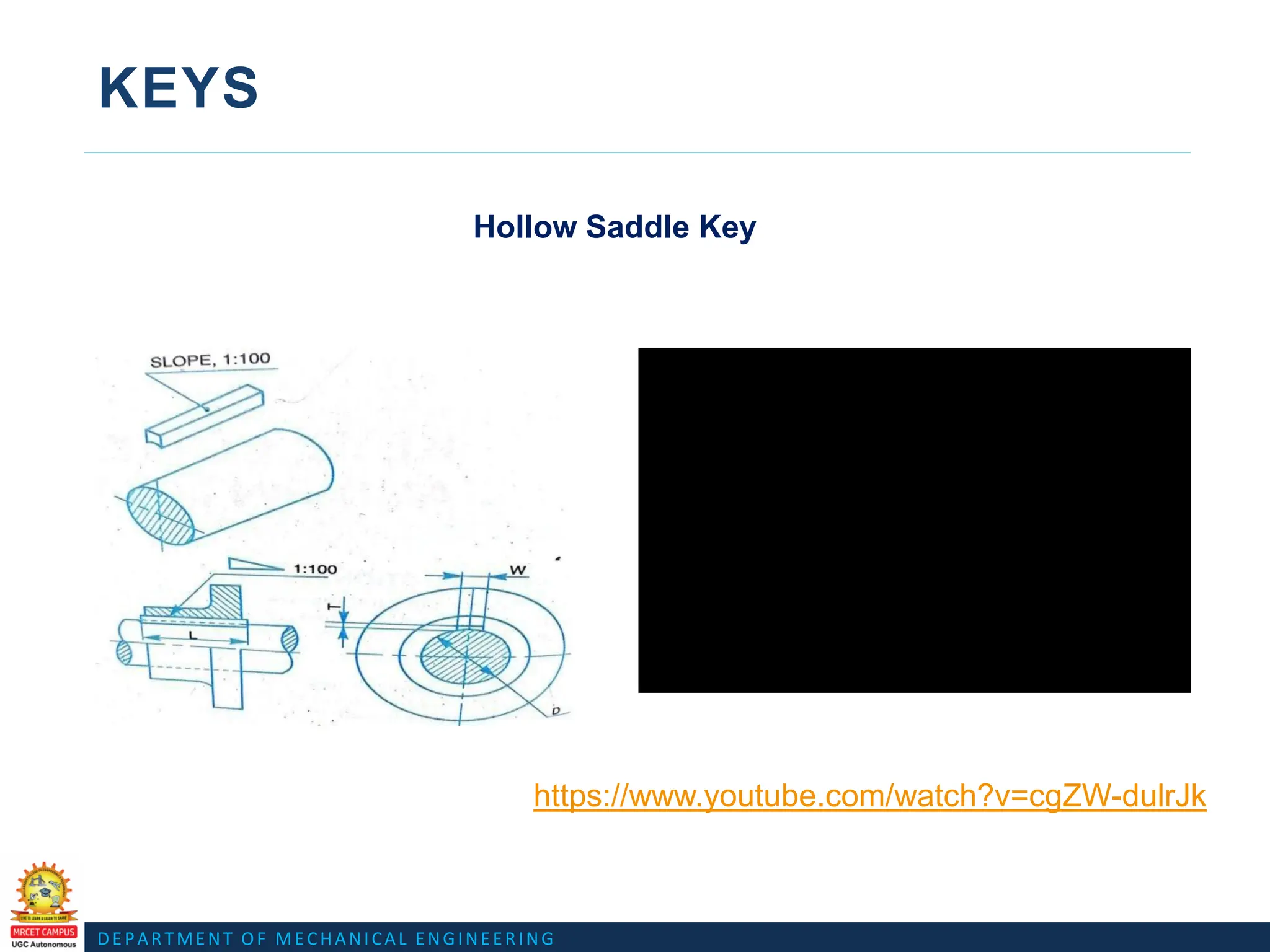
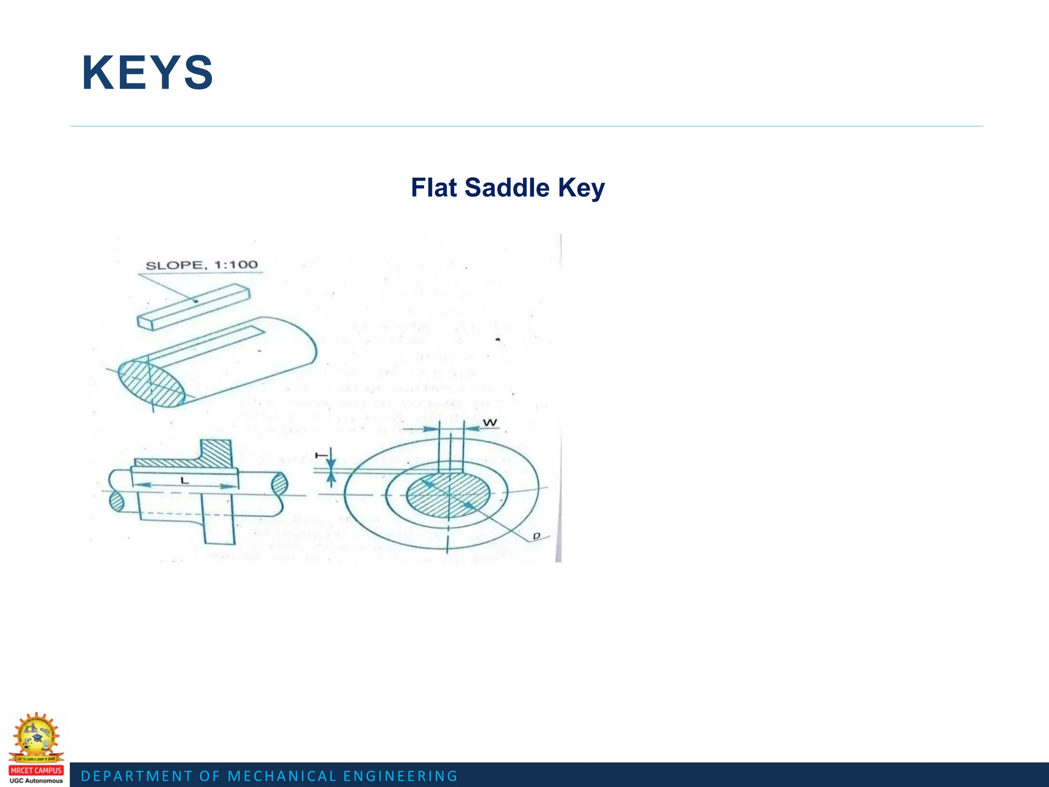
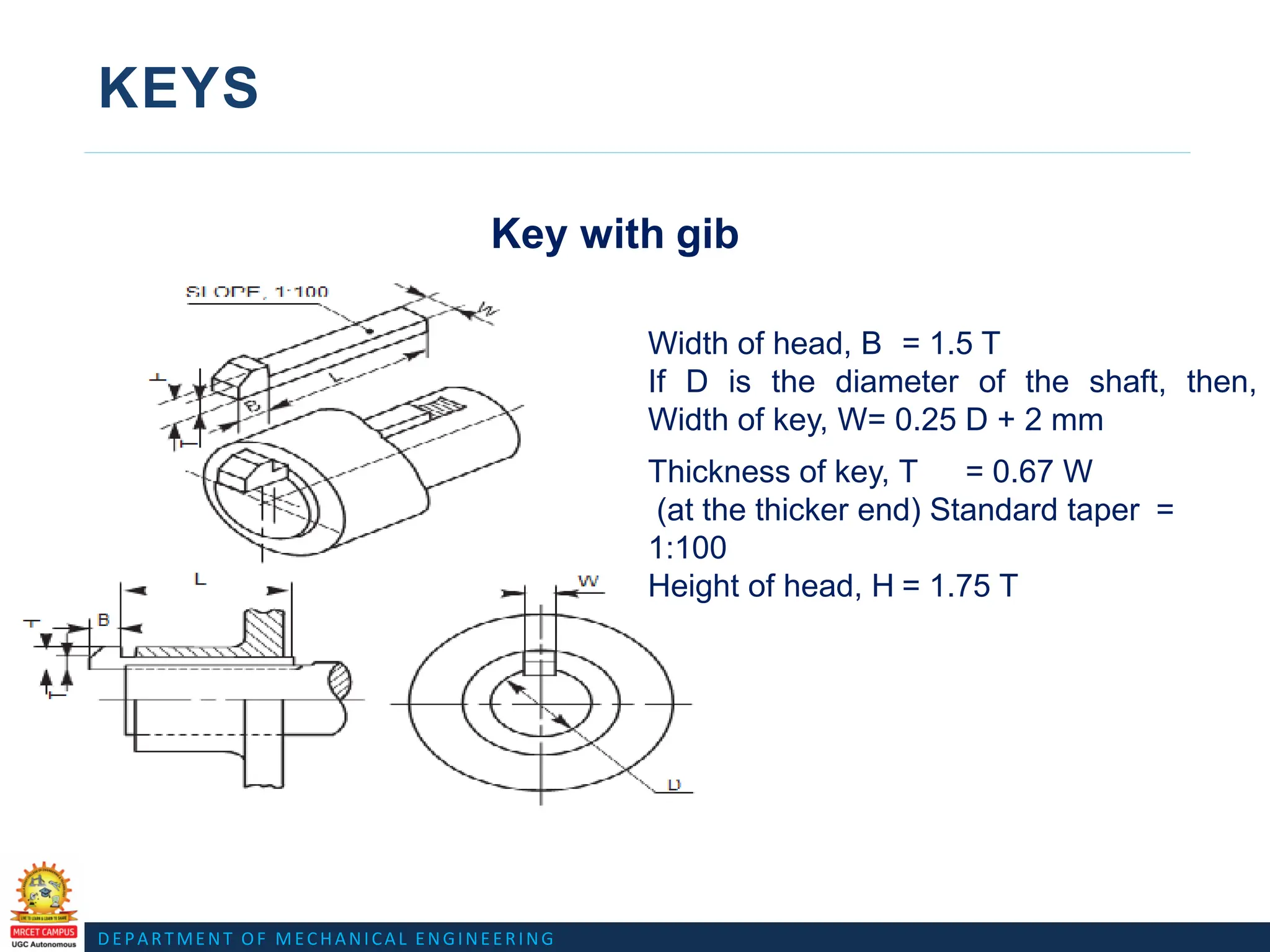
KEYS
Key with gib
Thickness of key, T = 0.67 W
(at the thicker end) Standard taper =
1:100
Height of head, H = 1.75 T
Width of head, B = 1.5 T
If D is the diameter of the shaft, then,
Width of key, W= 0.25 D + 2 mm
26.
DEPARTMENT OF MECHANICALENGINEERING
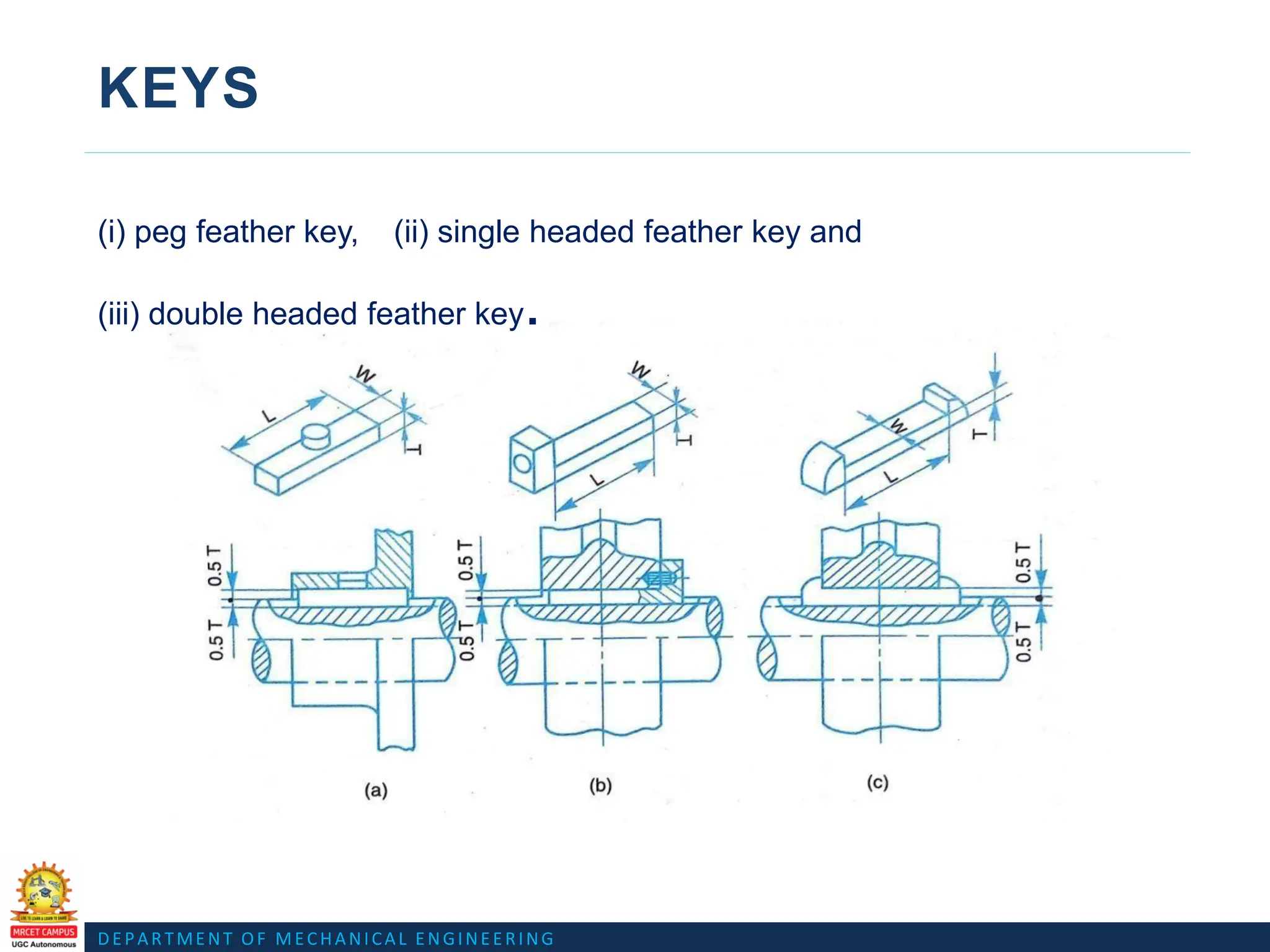
KEYS
(i) peg feather key, (ii) single headed feather key and
(iii) double headed feather key.
27.
DEPARTMENT OF MECHANICALENGINEERING
KEYS
(i) peg feather key, (ii) single headed feather key and
(iii) double headed feather key.
28.
DEPARTMENT OF MECHANICALENGINEERING
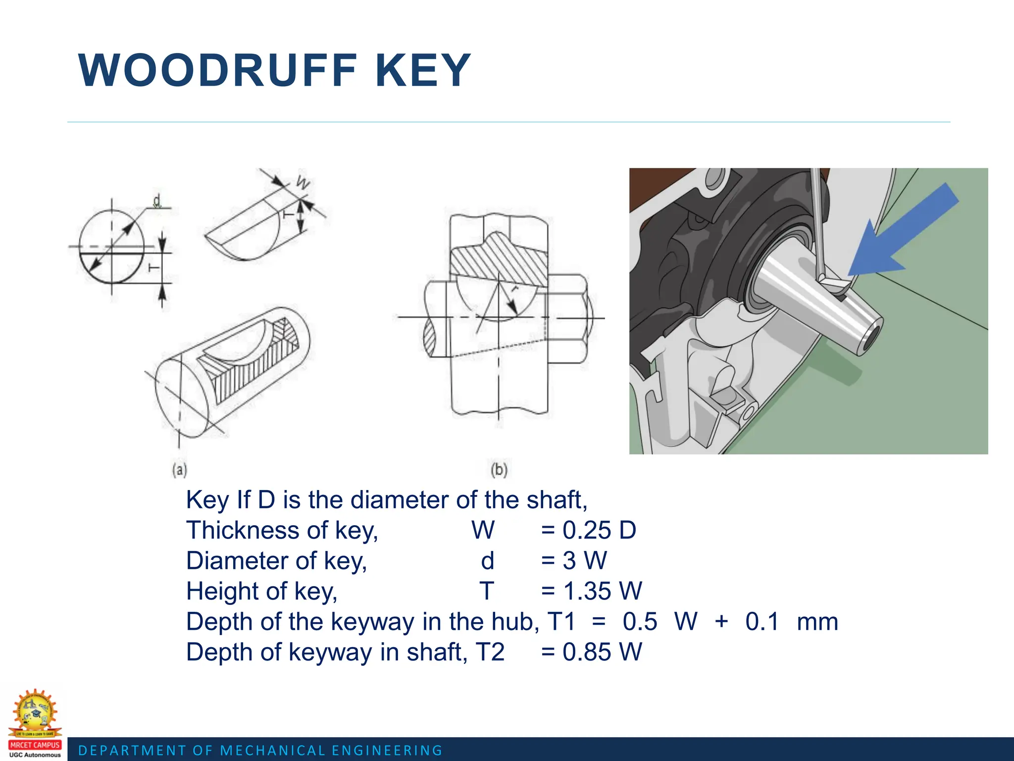
WOODRUFF KEY
Key If D is the diameter of the shaft,
Thickness of key, W = 0.25 D
Diameter of key, d = 3 W
Height of key, T = 1.35 W
Depth of the keyway in the hub, T1 = 0.5 W + 0.1 mm
Depth of keyway in shaft, T2 = 0.85 W
DEPARTMENT OF MECHANICALENGINEERING
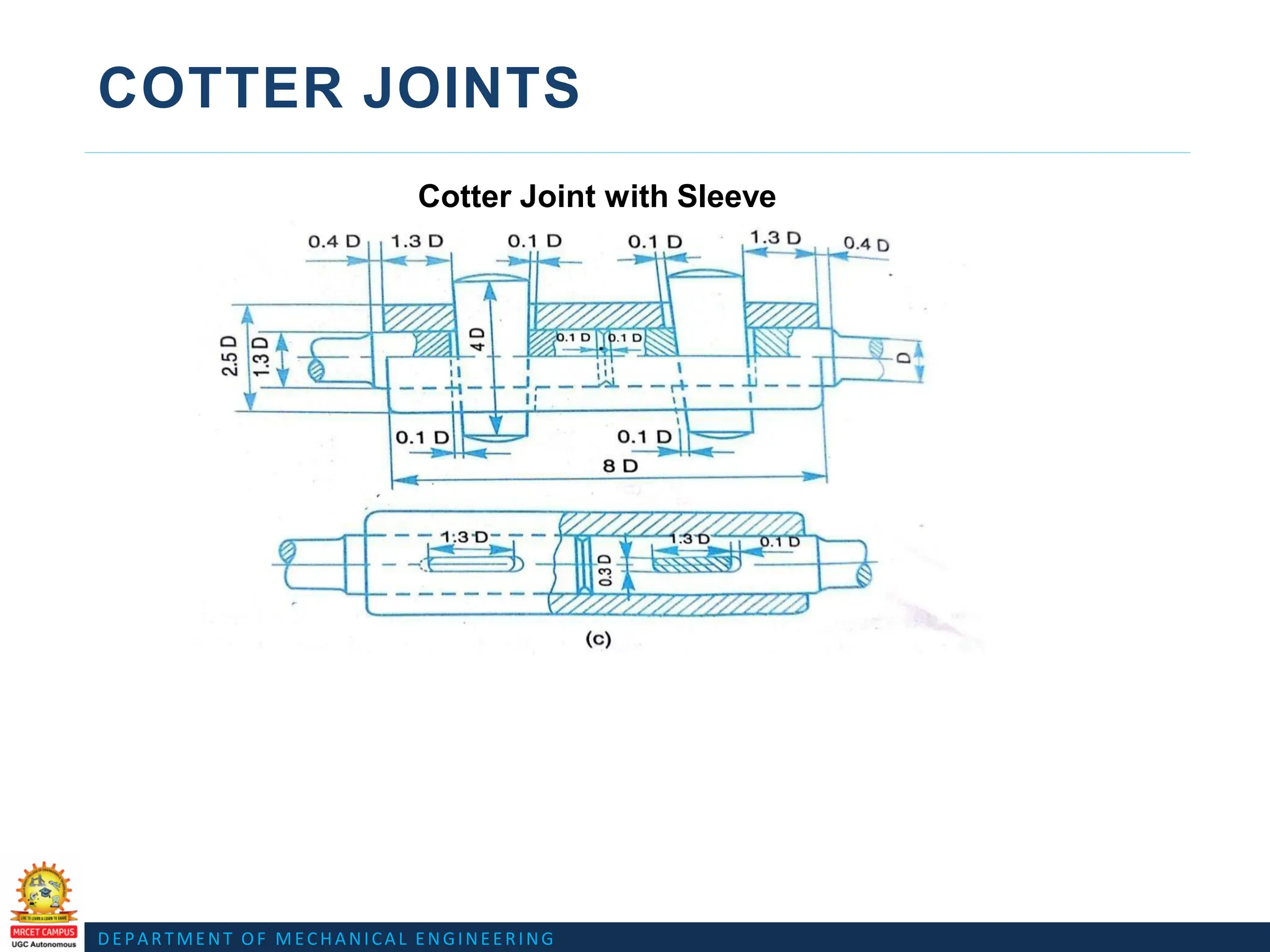
COTTER JOINTS
Cotter Joint with Sleeve
https://www.youtube.com/watch?v=_2h0N-b2Lm4
https://www.youtube.com/watch?v=Nu0PKhTz7JU
31.
DEPARTMENT OF MECHANICALENGINEERING
COTTER JOINTS
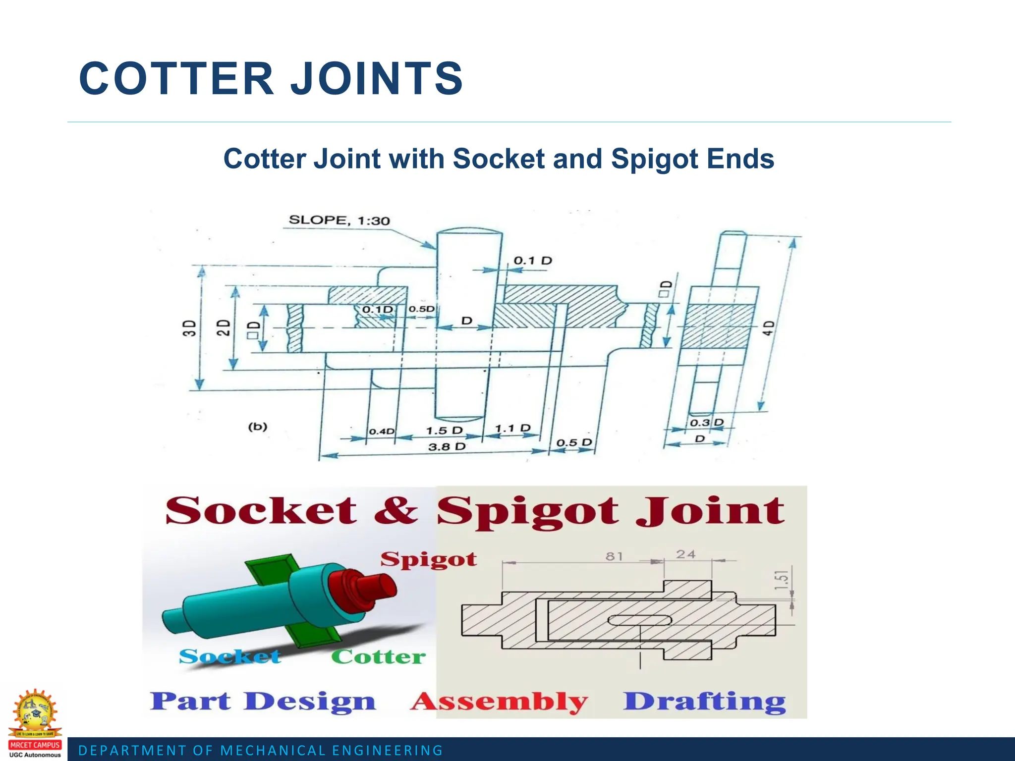
Cotter Joint with Socket and Spigot Ends
Fig. Cotter joint with socket and spigot ends
D
D
D
5
32.
DEPARTMENT OF MECHANICALENGINEERING
COTTER JOINTS
Cotter Joint with Socket and Spigot Ends
https://www.youtube.com/watch?v=esfr74WhbYg
DEPARTMENT OF MECHANICALENGINEERING
PIVOT OR FOOT-STEP BEARING
https://www.youtube.com/watch?v=l4HM1R5dNHo
51.
DEPARTMENT OF MECHANICALENGINEERING
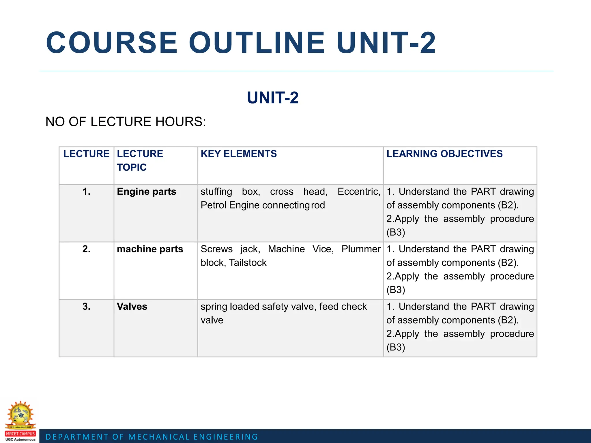
COURSE OUTLINE UNIT-2
UNIT-2
NO OF LECTURE HOURS:
LECTURE LECTURE
TOPIC
KEY ELEMENTS LEARNING OBJECTIVES
1. Engine parts stuffing box, cross head, Eccentric,
Petrol Engine connectingrod
1. Understand the PART drawing
of assembly components (B2).
2.Apply the assembly procedure
(B3)
2. machine parts Screws jack, Machine Vice, Plummer
block, Tailstock
1. Understand the PART drawing
of assembly components (B2).
2.Apply the assembly procedure
(B3)
3. Valves spring loaded safety valve, feed check
valve
1. Understand the PART drawing
of assembly components (B2).
2.Apply the assembly procedure
(B3)
52.
DEPARTMENT OF MECHANICALENGINEERING
COURSE OBJECTIVES
UNIT - 2 CO4: students learn about the drawings of assembled views for the part drawings of the following
using conventions like Engine parts.
CO5: students learn about the drawings of assembled views for the part drawings of the following
using conventions like machine parts, Valves.
DEPARTMENT OF MECHANICALENGINEERING
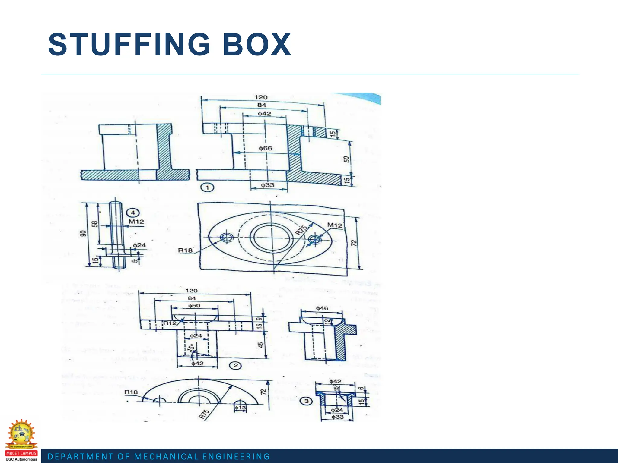
STUFFING BOX
https://www.youtube.com/watch?v=rLDC1L1WFW8
Assembly Drawing Link
https://www.youtube.com/watch?v=8ar0oYyF5a8
Assembly Drawing animation Link
DEPARTMENT OF MECHANICALENGINEERING
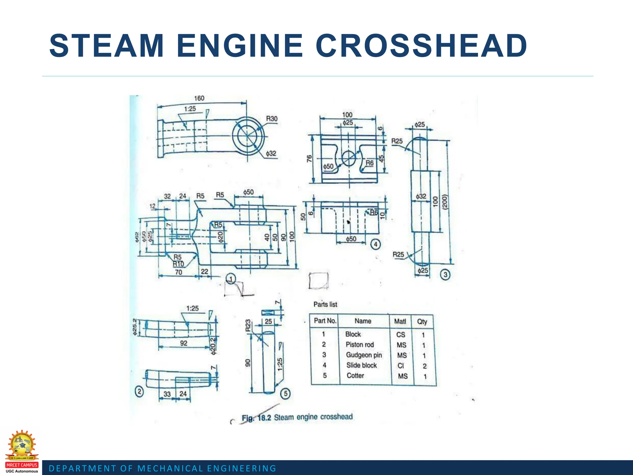
STEAM ENGINE CROSSHEAD
https://www.youtube.com/watch?v=iESHDRW1Rks
https://www.youtube.com/watch?v=z9Sudq0vUSE
Assembly Drawing Link
Assembly Drawing animation Link
DEPARTMENT OF MECHANICALENGINEERING
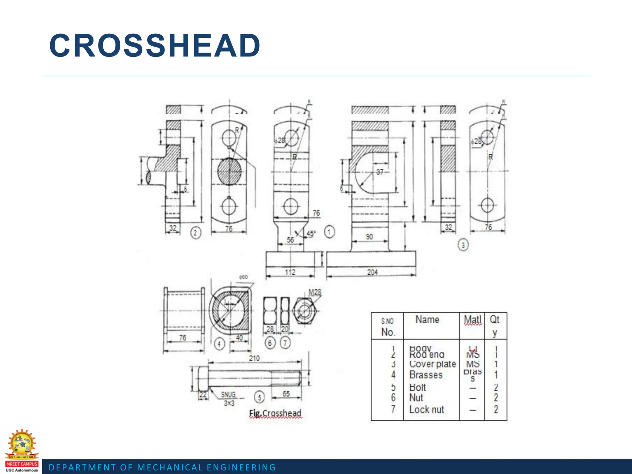
CROSSHEAD
https://www.youtube.com/watch?v=Ept1ztQsXsM
https://www.youtube.com/watch?v=jm5sOOhNo6c
Assembly Drawing Link
Assembly Drawing animation Link
DEPARTMENT OF MECHANICALENGINEERING
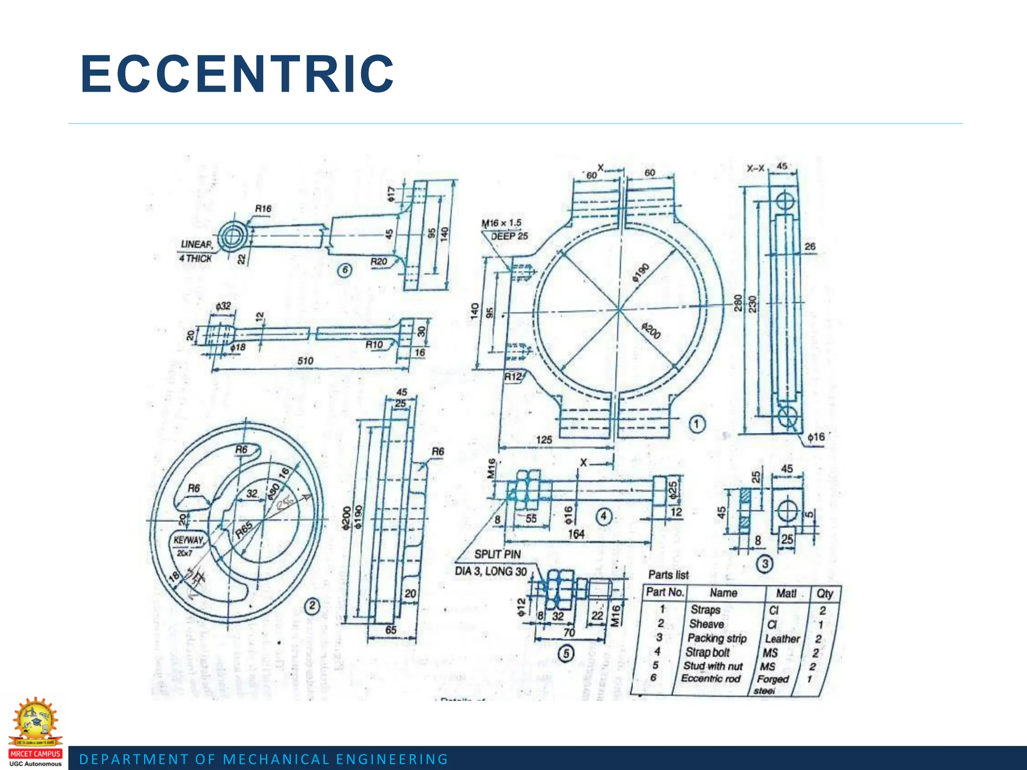
ECCENTRIC
Assembly Drawing Link
Assembly Drawing animation Link
https://www.youtube.com/watch?v=-Lts0axaeis
https://www.youtube.com/watch?v=xbzWbB-pLL4
DEPARTMENT OF MECHANICALENGINEERING
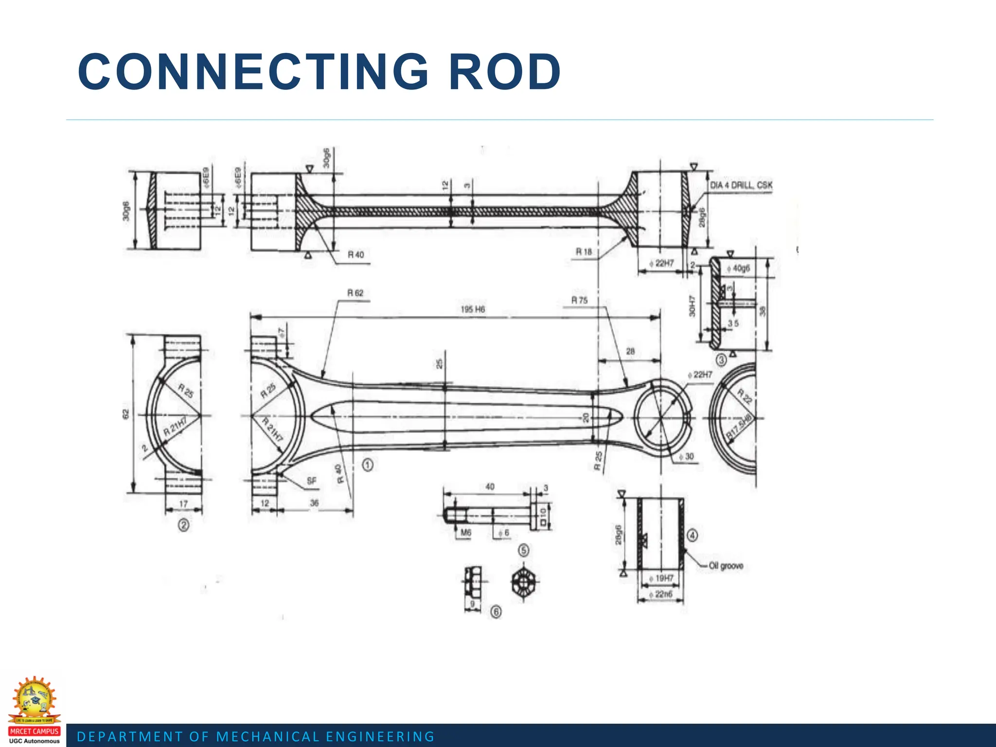
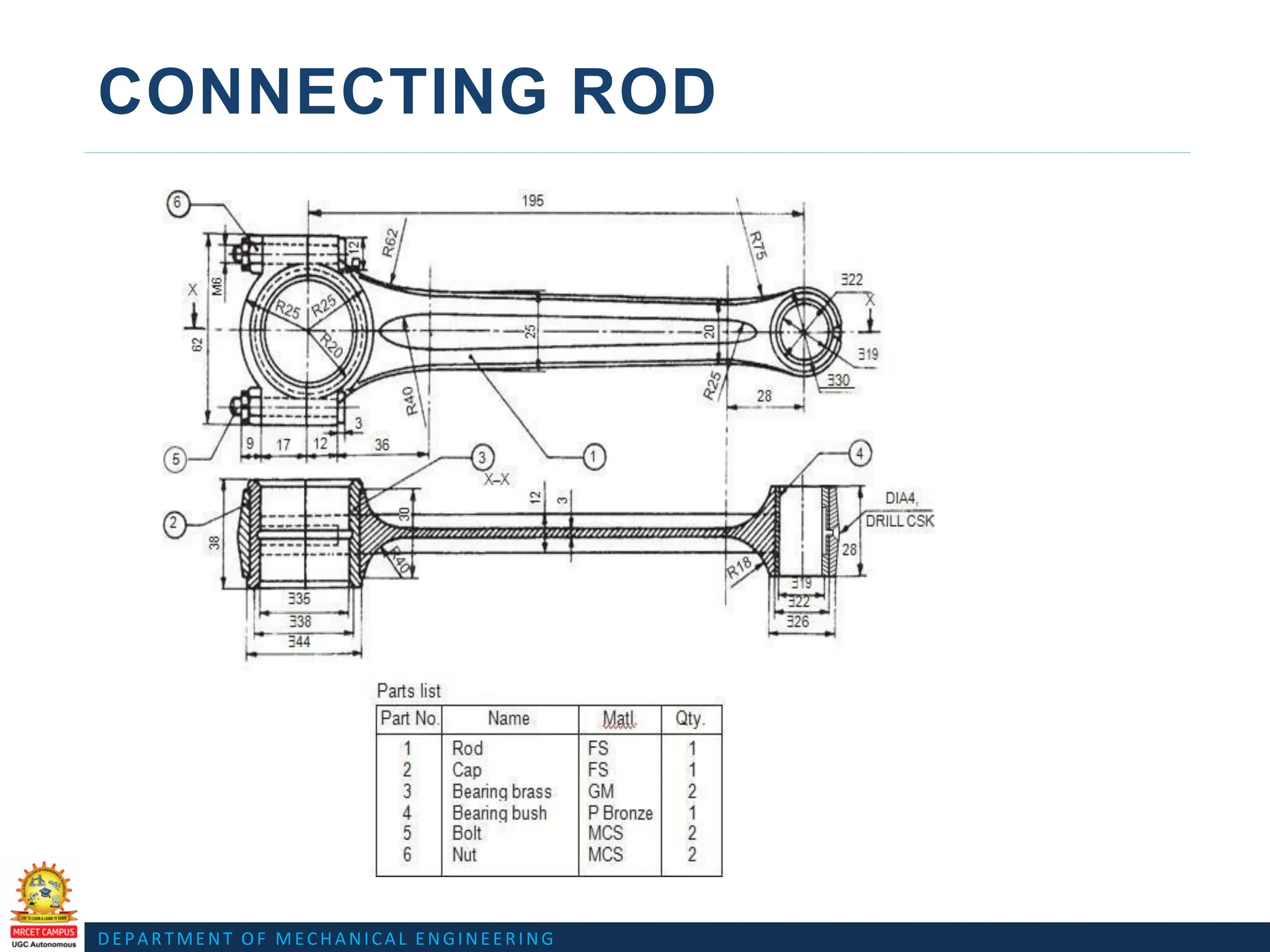
CONNECTING ROD
Assembly Drawing Link
Assembly Drawing animation Link
https://www.youtube.com/watch?v=ZoCn4Pb6rLU
https://www.youtube.com/watch?v=6emnuUPytLo
DEPARTMENT OF MECHANICALENGINEERING
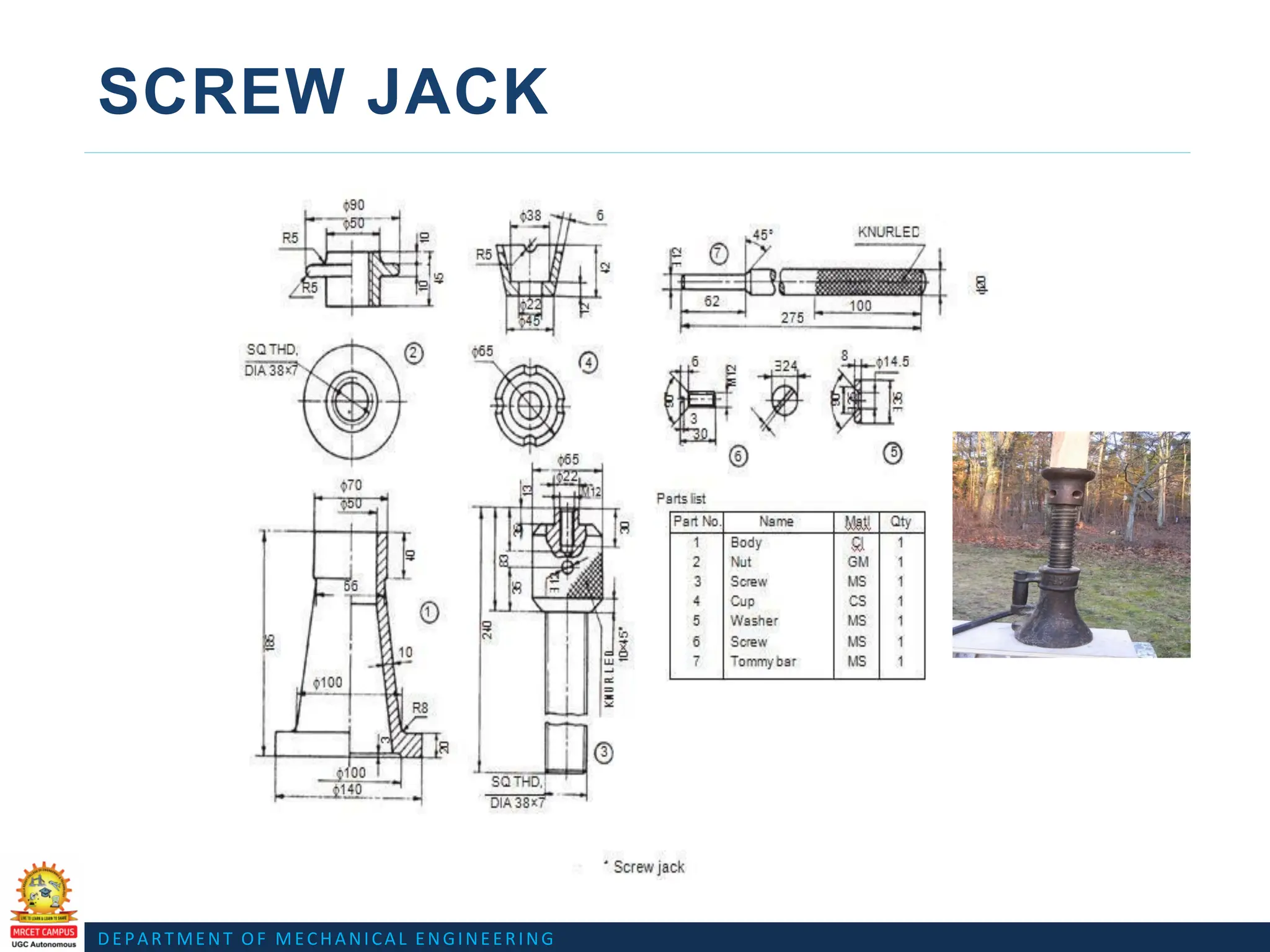
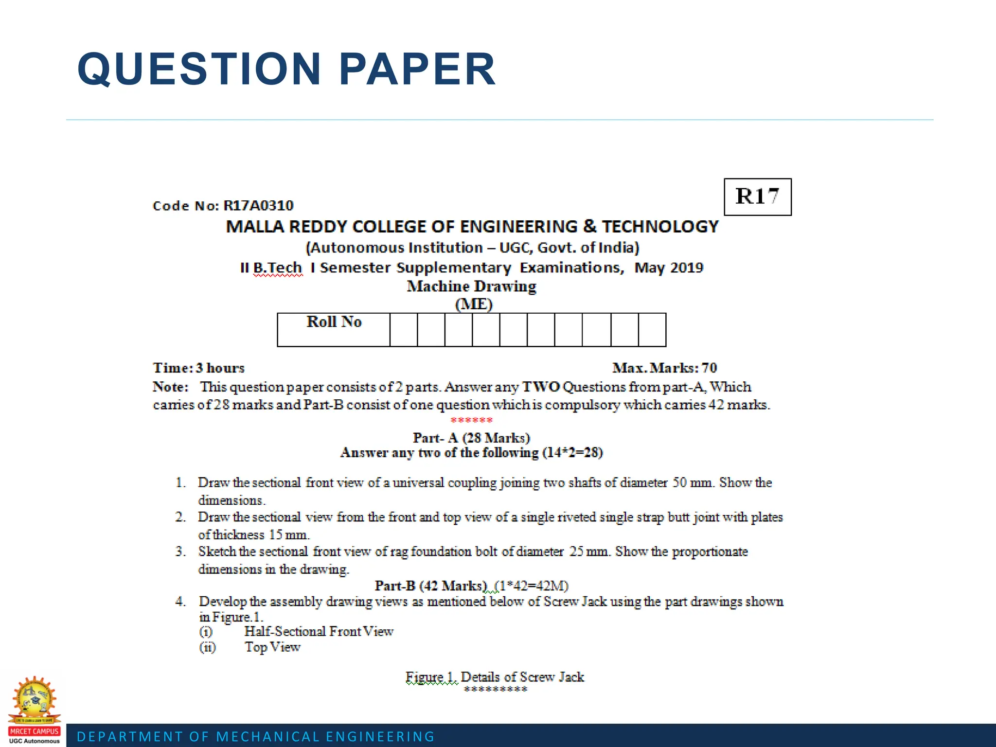
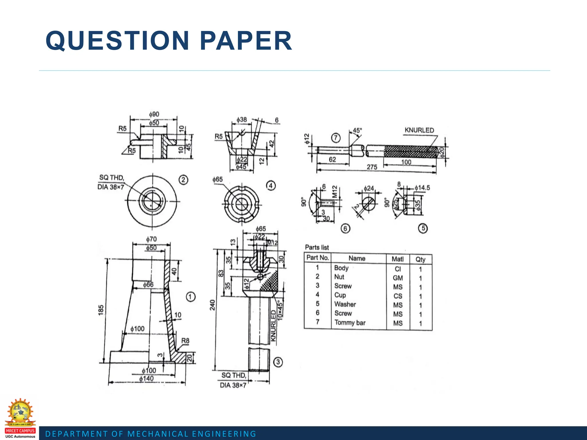
SCREW JACK
Assembly Drawing Link
Assembly Drawing animation Link
https://www.youtube.com/watch?v=H_nOMxAoI84
https://www.youtube.com/watch?v=r7ajkX1DrYw
DEPARTMENT OF MECHANICALENGINEERING
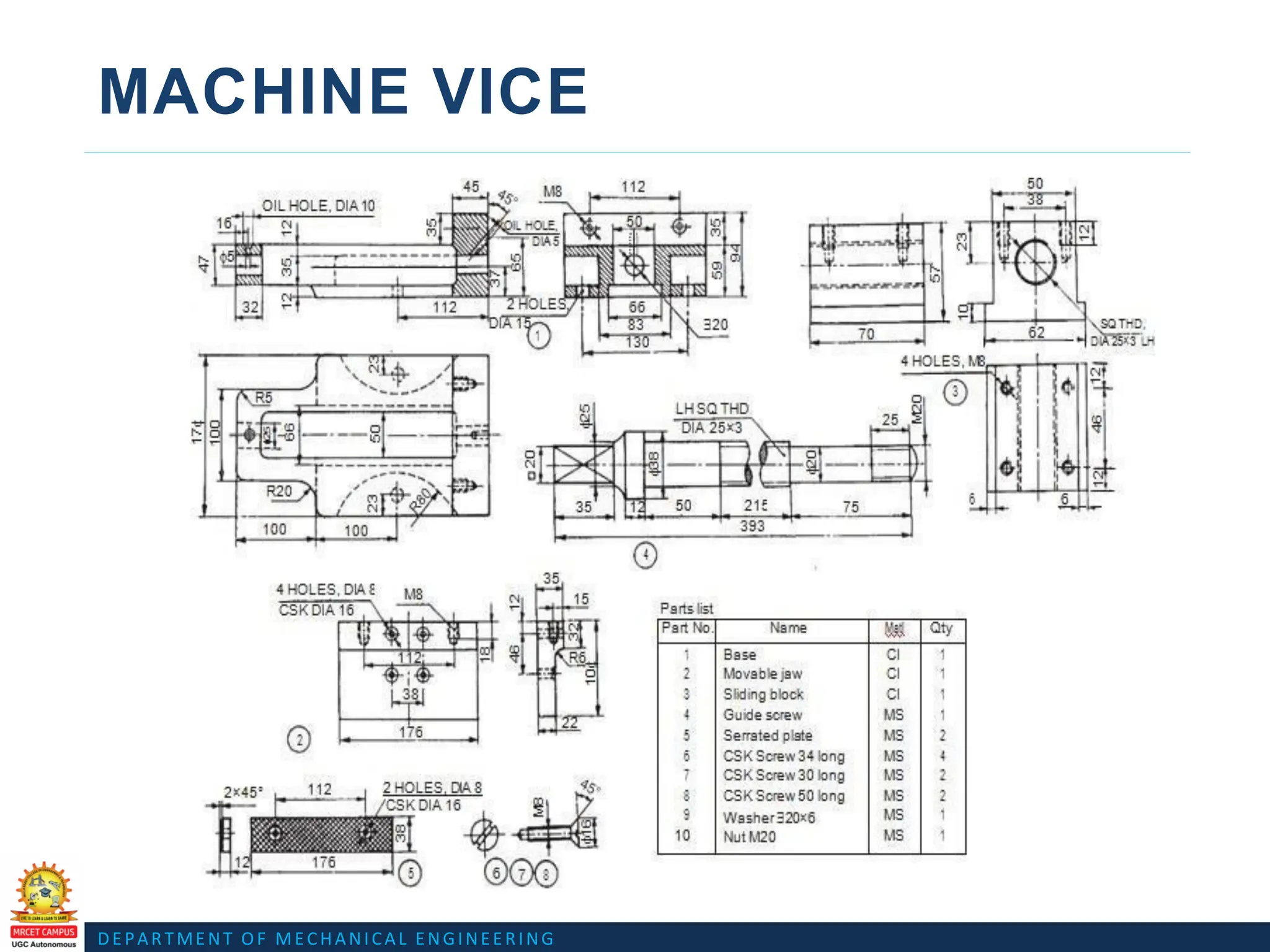
MACHINE VICE
https://www.youtube.com/watch?v=Ss5nBSIr5MY
https://www.youtube.com/watch?v=sghEwiN2tkE
Assembly Drawing Link
Assembly Drawing animation Link
DEPARTMENT OF MECHANICALENGINEERING
MACHINE VICE
Assembly Drawing Link
https://www.youtube.com/watch?v=Y-_LjEjyLhA
https://www.youtube.com/watch?v=igsyruvtIWg
Assembly Drawing animation Link
DEPARTMENT OF MECHANICALENGINEERING
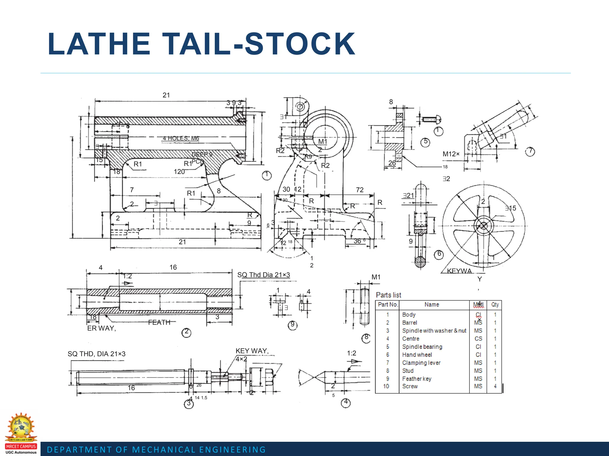
LATHE TAIL-STOCK
https://www.youtube.com/watch?v=16SufCt10WY
Assembly Drawing Link
Assembly Drawing animation Link
https://www.youtube.com/watch?v=rrnbS10iYDA
72.
DEPARTMENT OF MECHANICALENGINEERING
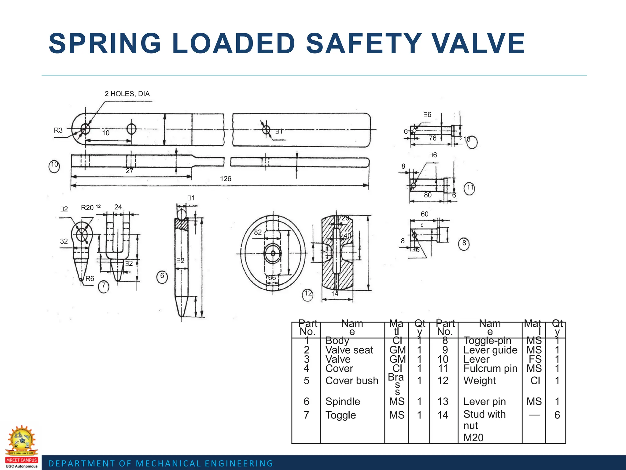
SPRING LOADED SAFETY VALVE
2 HOLES, DIA
$6
R3 10 $1 6
76 3 13
$6
10
27
8
126
11
$1 80 6
$2 R20 12 24
20
60
5
82
32
40
8 8
$6
$2 $2
R6 6 66
7
12 14
Part
No.
Nam
e
Ma
tl
Qt
y
Part
No.
Nam
e
Mat
l
Qt
y
1 Body Cl 1 8 Toggle-pin MS 1
2 Valve seat GM 1 9 Lever guide MS 1
3 Valve GM 1 10 Lever FS 1
4 Cover Cl 1 11 Fulcrum pin MS 1
5 Cover bush Bra
s
s
1 12 Weight Cl 1
6 Spindle MS 1 13 Lever pin MS 1
7 Toggle MS 1 14 Stud with
nut
M20
— 6
73.
DEPARTMENT OF MECHANICALENGINEERING
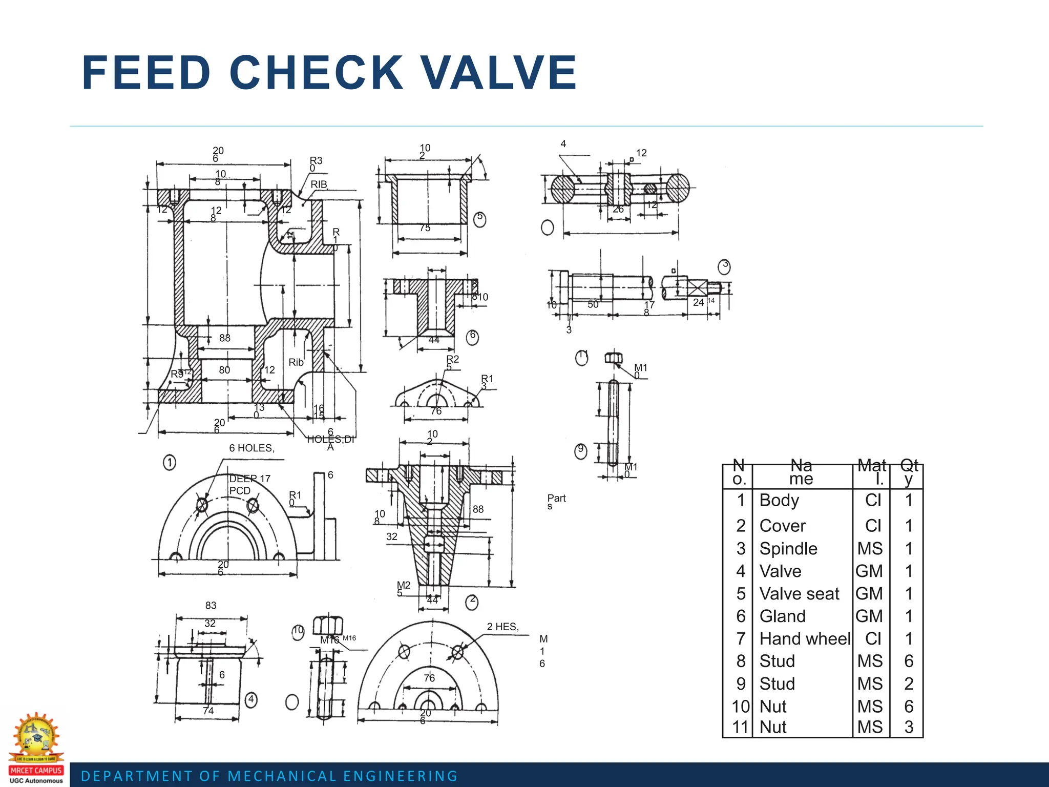
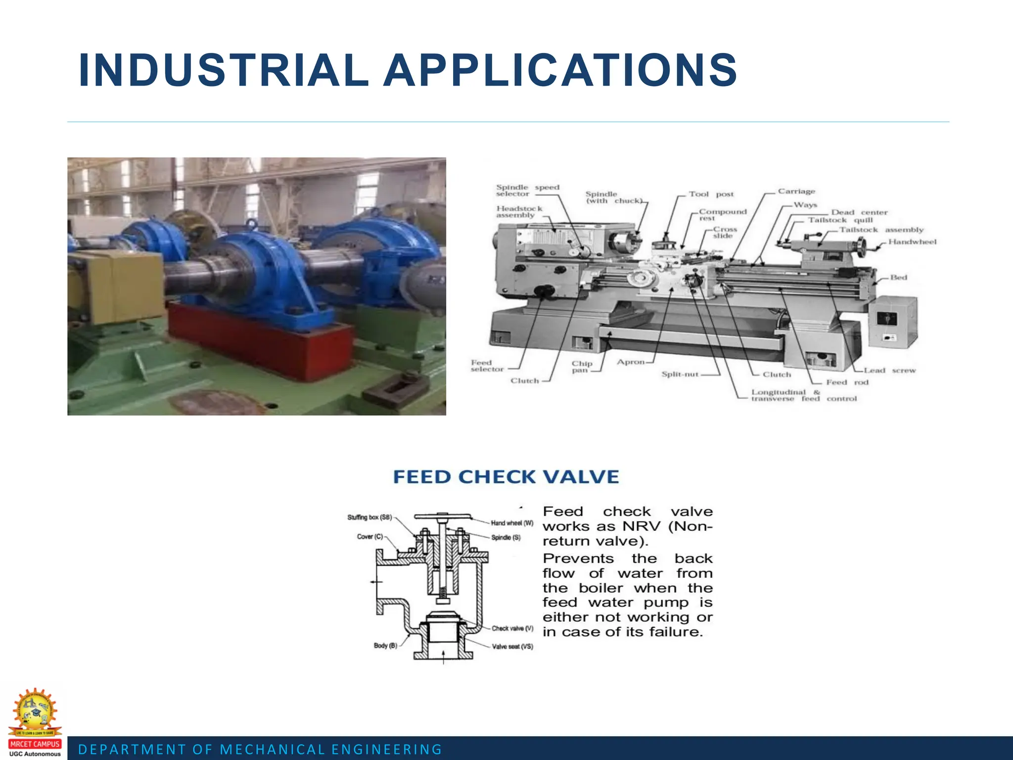
FEED CHECK VALVE
20
6
10
2
4
12
R3
0
10
8 RIB
,
12 12
8
12
R
1
0
12
5
26
75
8
8
3
10
10 50 17
8
24 14
3
88 44
6
11
Rib R2
5
R912 80 12 M1
0
R1
3
13
0
16
15 76
20
6 6
HOLES,DI
A
6
10
2
6 HOLES,
DEEP 17
PCD
9
M1
0
R1
0 Part
s
10
8
88
32
20
6
M2
5
83
44 2
32
10
M16 M16
2 HES,
M
1
6
6 76
4
74 20
6
N
o.
Na
me
Mat
l.
Qt
y
1 Body Cl 1
2 Cover Cl 1
3 Spindle MS 1
4 Valve GM 1
5 Valve seat GM 1
6 Gland GM 1
7 Hand wheel Cl 1
8 Stud MS 6
9 Stud MS 2
10 Nut MS 6
11 Nut MS 3
74.
DEPARTMENT OF MECHANICALENGINEERING
FEED CHECK VALVE
https://www.youtube.com/watch?v=KCIy0n4tAUo
Assembly Drawing Link
Assembly Drawing animation Link
https://www.youtube.com/watch?v=unMZIAiuzwY