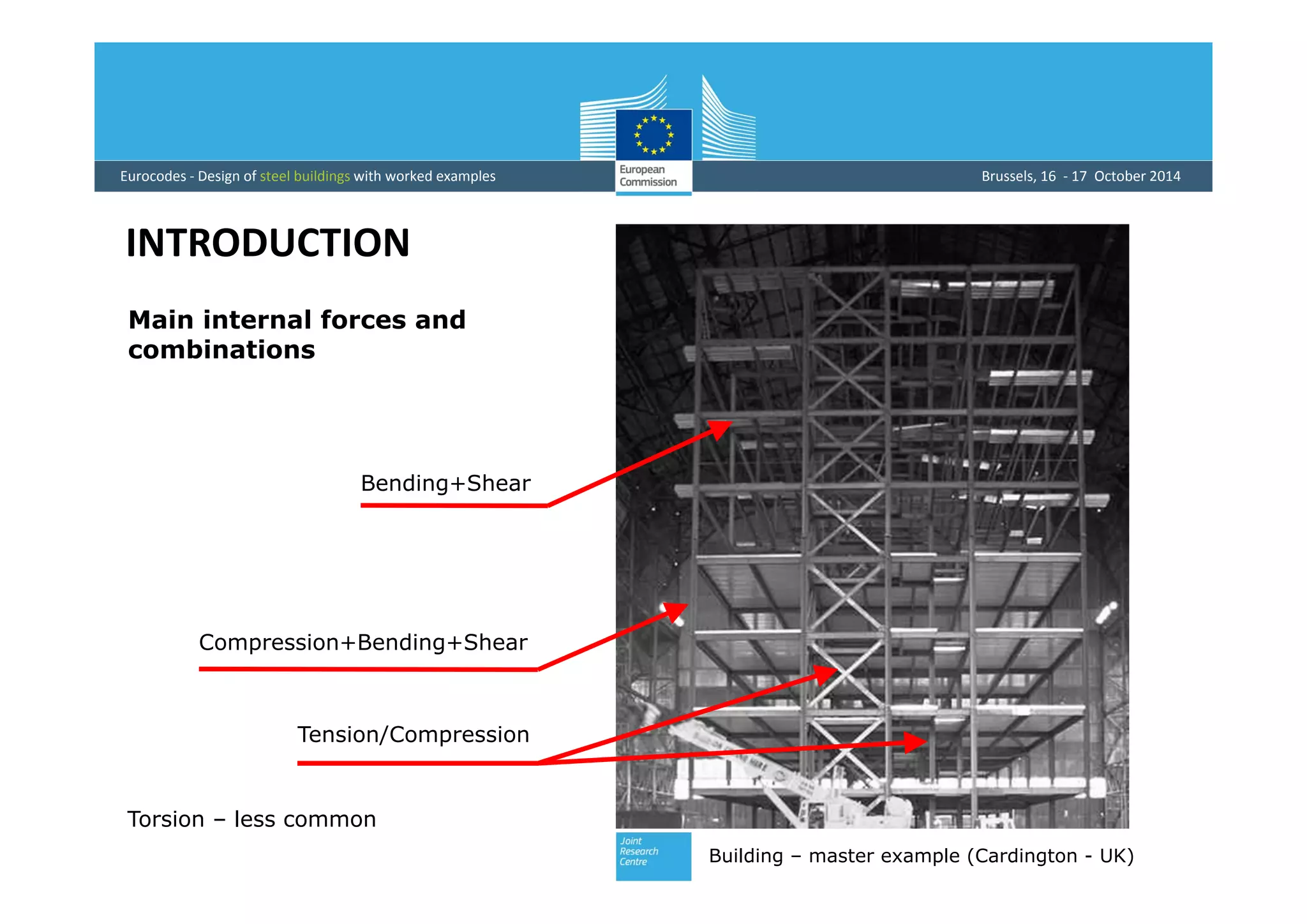
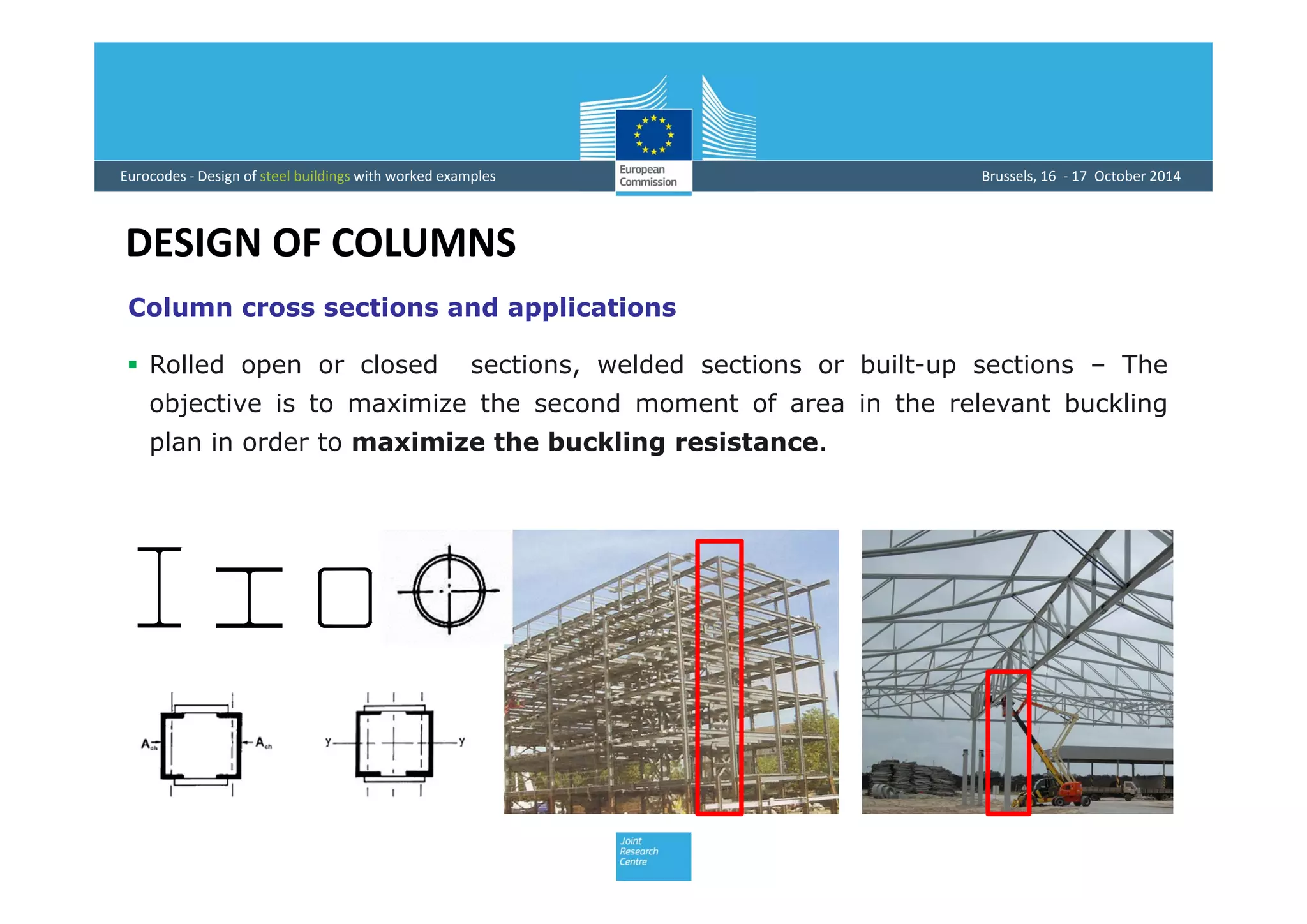
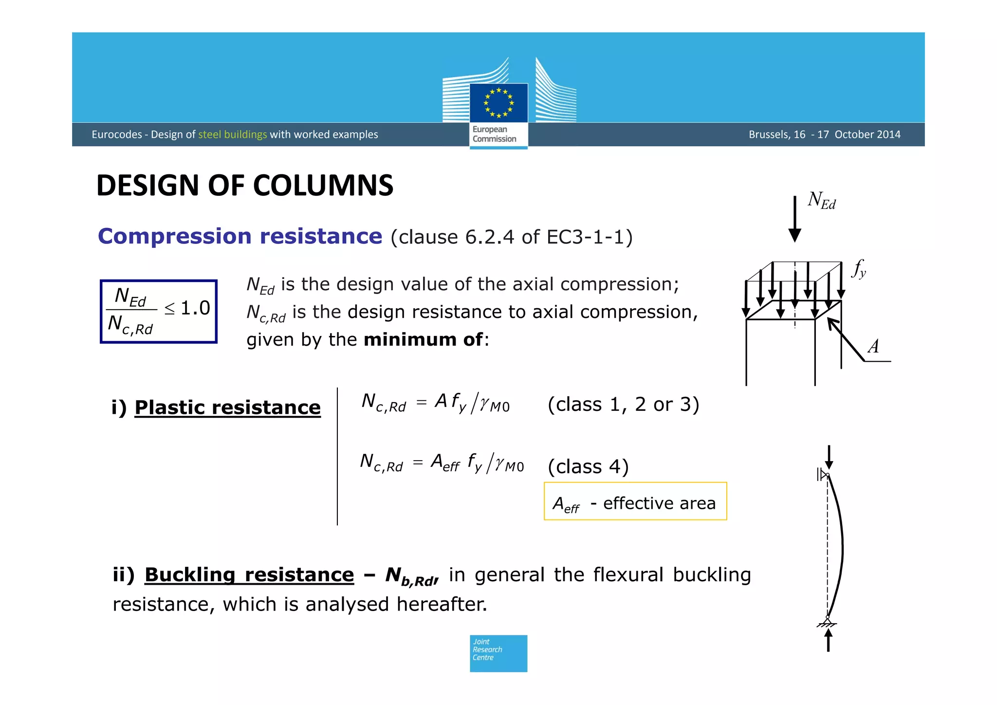
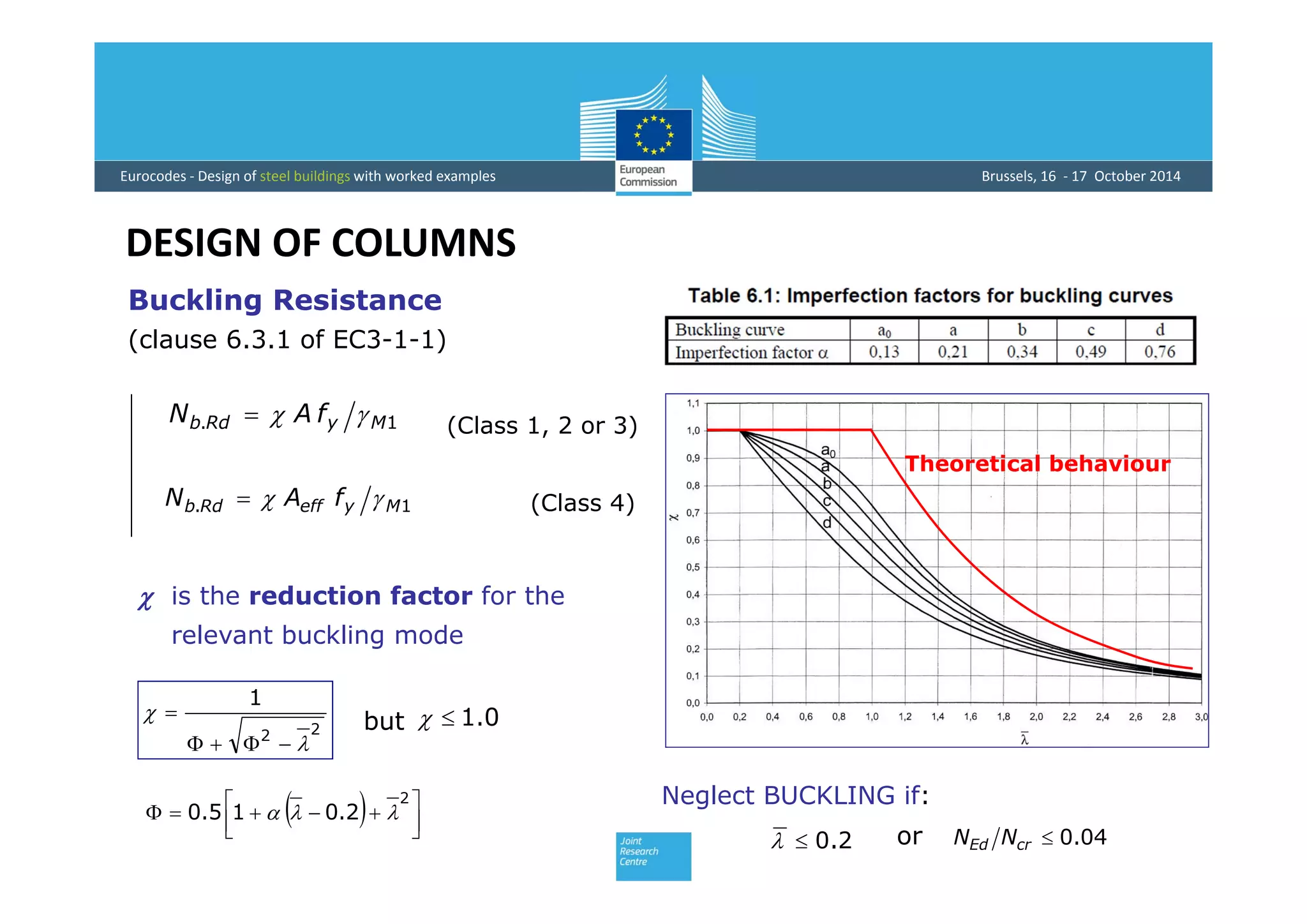
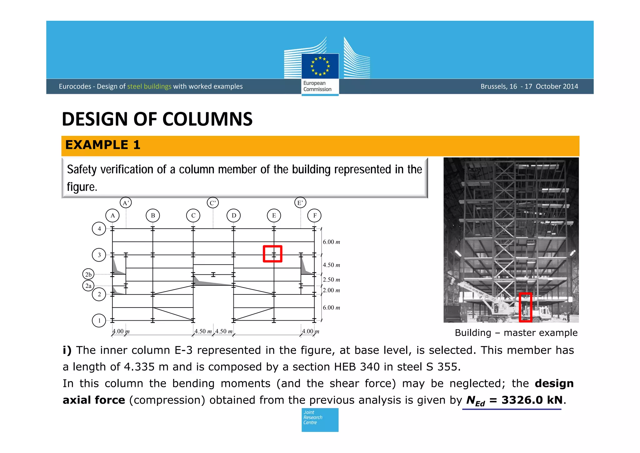
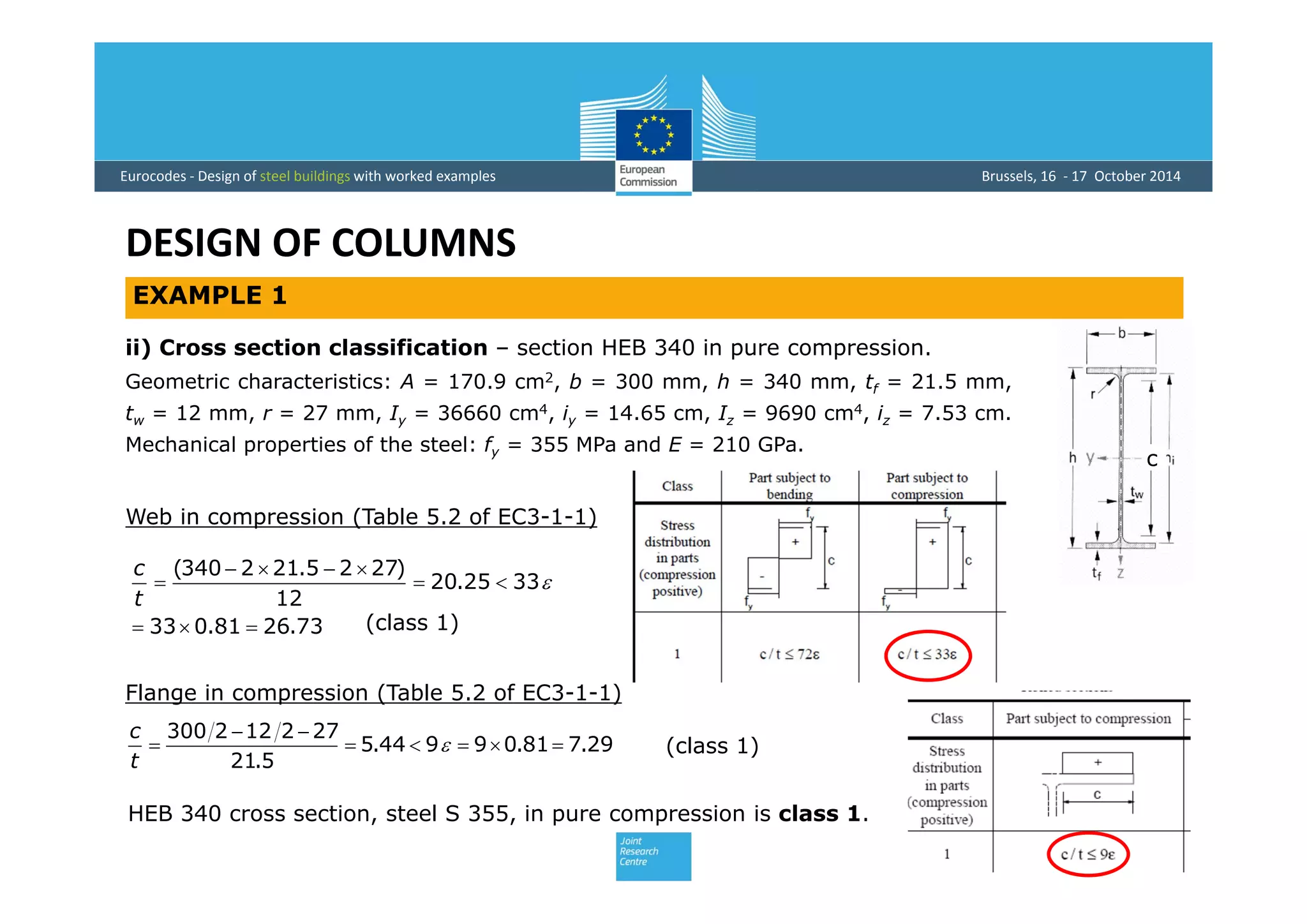
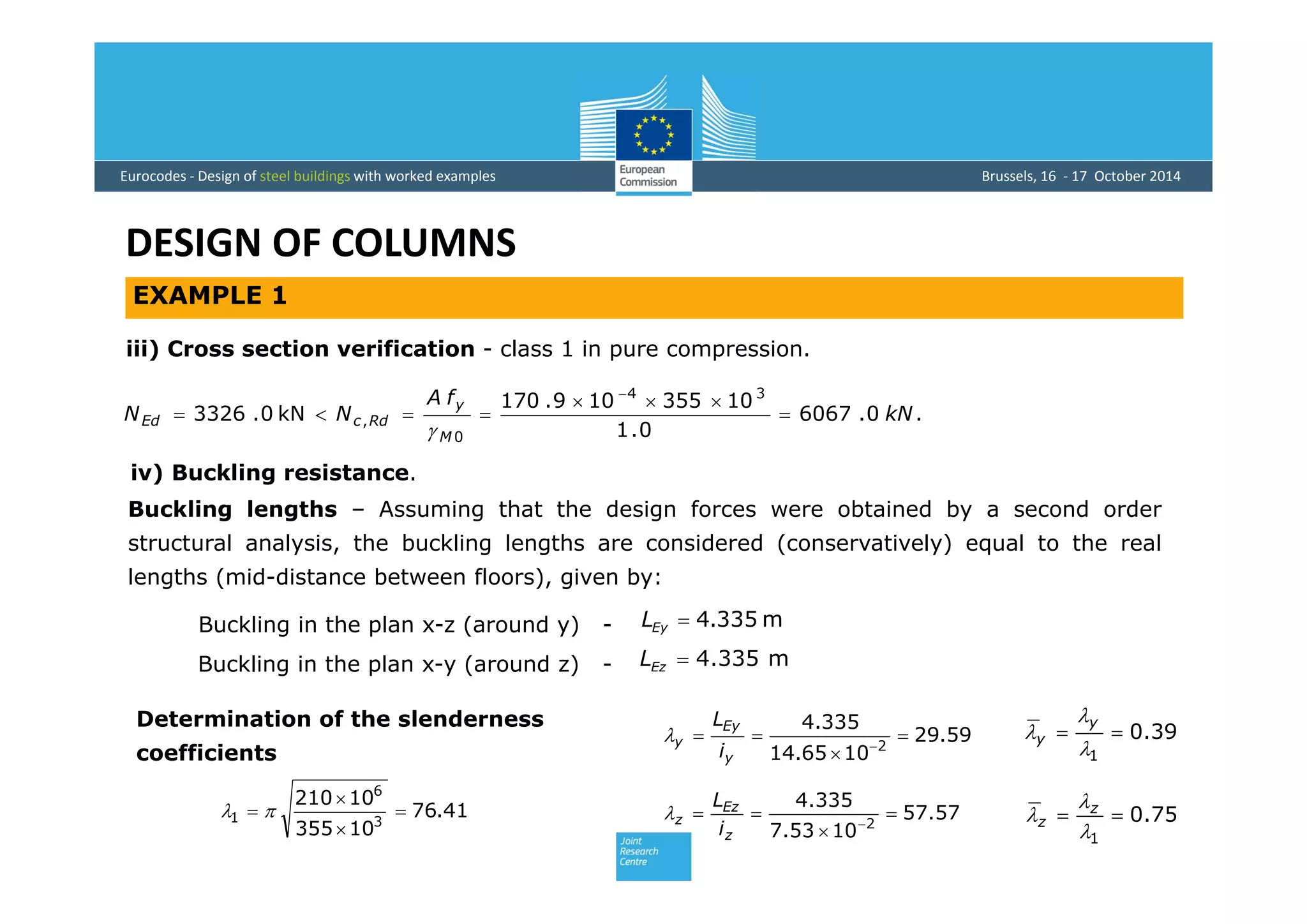
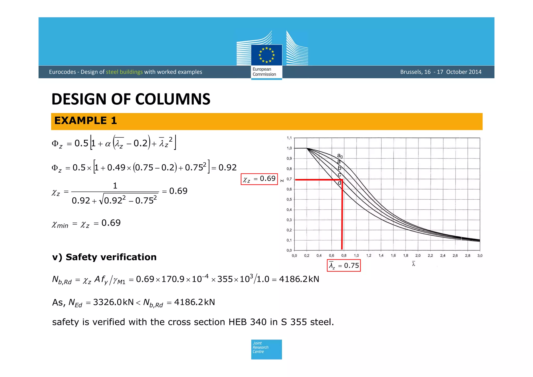
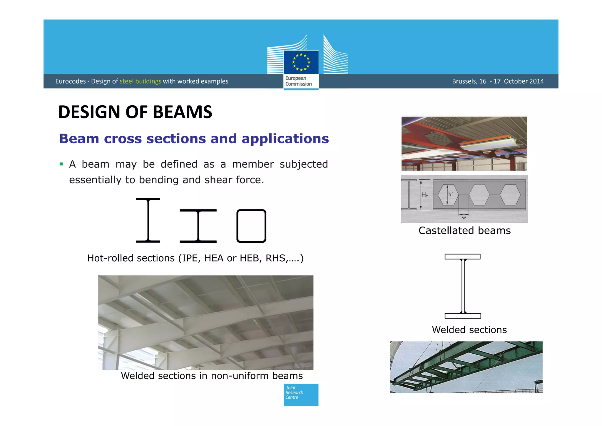
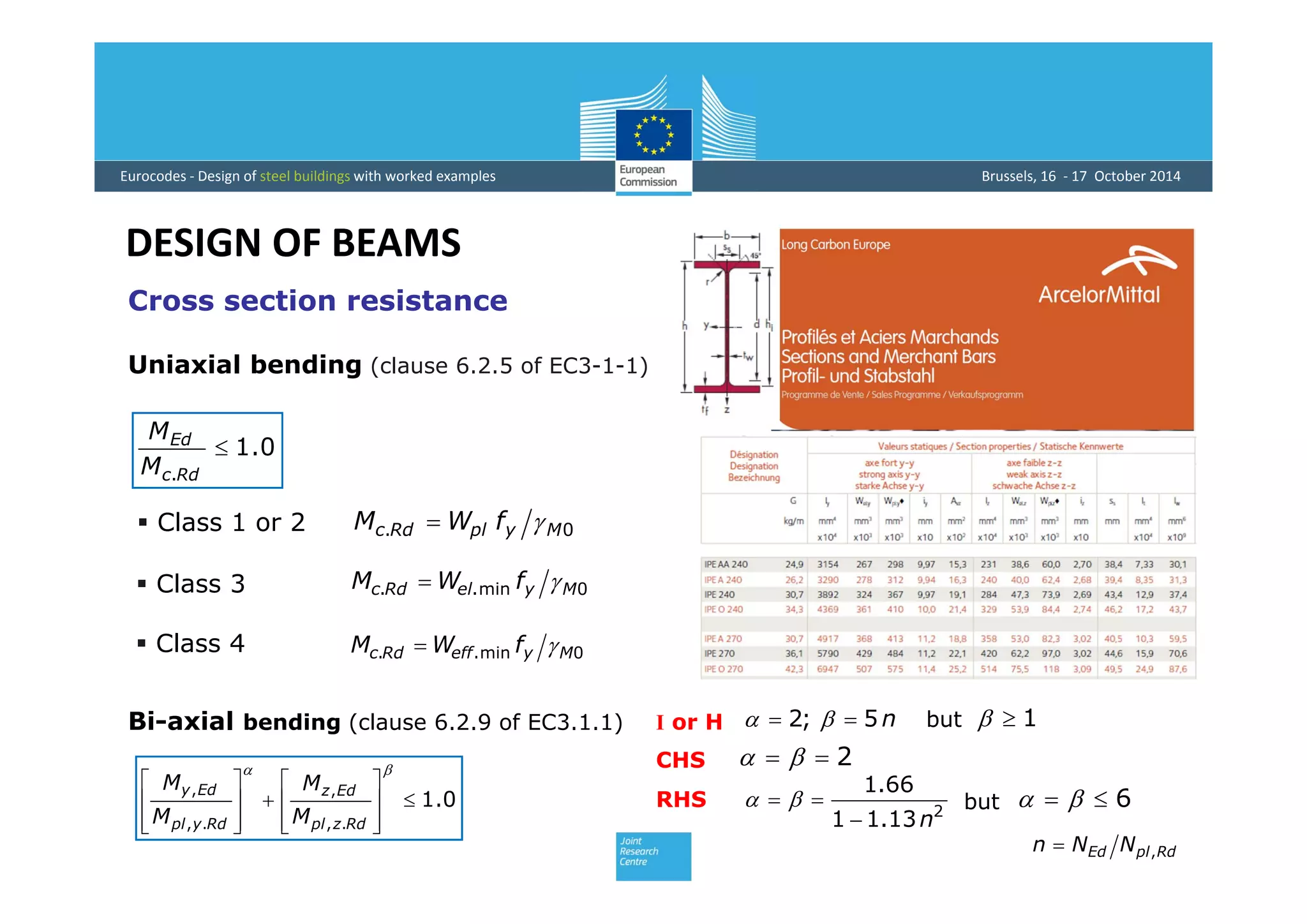
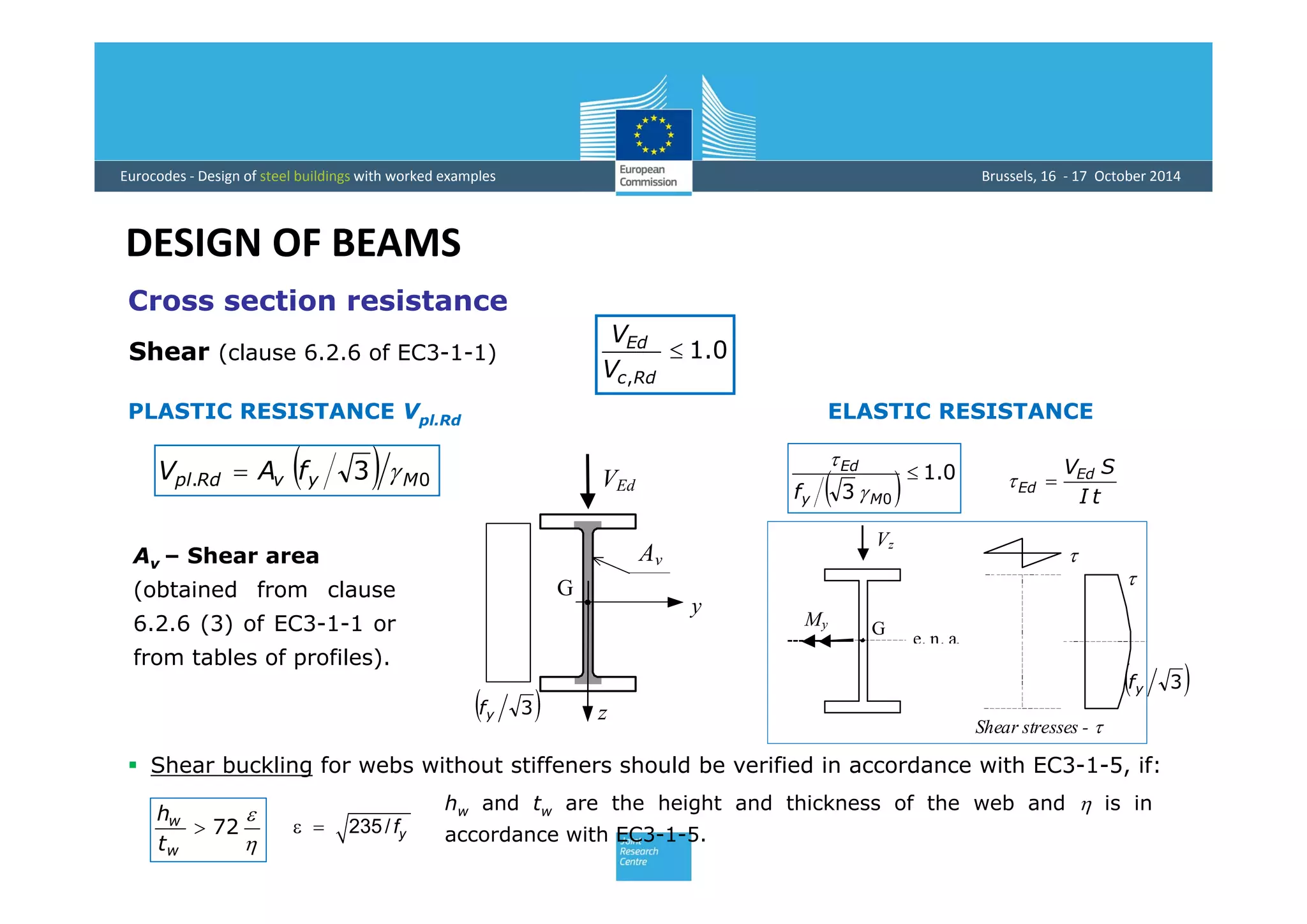
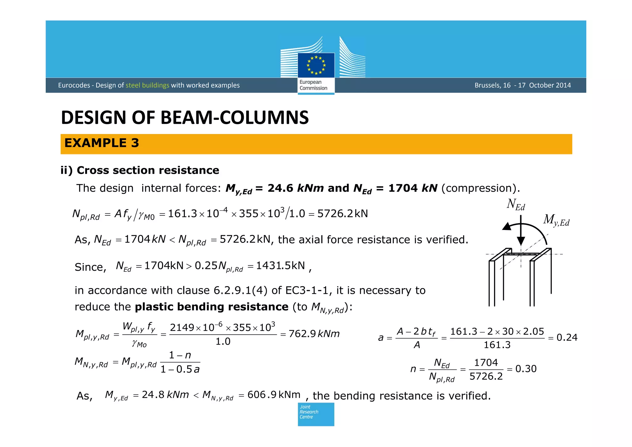
SlideShare a Scribd company logo
Design of Members
Rui Simões
Department of Civil Engineering 
University of Coimbra
Eurocodes ‐ Design of steel buildings with worked examples Brussels, 16  ‐ 17  October 2014
Contents
 Introduction
 Design of columns
 Design of beams
 Design of beam‐columns
Eurocodes ‐ Design of steel buildings with worked examples Brussels, 16  ‐ 17  October 2014
INTRODUCTION
Main internal forces and
combinations
Compression+Bending+Shear
Bending+Shear
Tension/Compression
Torsion – less common
Building – master example (Cardington - UK)
Eurocodes ‐ Design of steel buildings with worked examples Brussels, 16  ‐ 17  October 2014
INTRODUCTION
Member design:
i) resistance of cross sections;
ii) member buckling resistance.
 Clause 6.2 of Eurocode 3, part 1.1 provides different
approaches, depending of cross section shape, cross section
class and type of internal forces (N, M+V, N+M+V,….):
– elastic criteria (clause 6.2.1(5));
My G
Vz
NEd
My,Ed
RESISTANCE OF CROSS SECTIONS
 Cross section classification - Class 1; Class 2; Class 3 and Class 4.
13
2
00
,
0
,
2
0
,
2
0
,












































My
Ed
My
Edz
My
Edx
My
Edz
My
Edx
fffff 









Eurocodes ‐ Design of steel buildings with worked examples Brussels, 16  ‐ 17  October 2014
INTRODUCTION
MEMBER BUCKLING RESISTANCE
 Buckling resistance (clause 6.3 of Eurocode 3,
part 1.1) must be checked in all members
submitted to compressive stresses, which are:
– members under axial compression N;
– members under bending moment M;
– or under a combination of both (M+N).
1
,
,
,
,

Rdz
Edz
Rdy
Edy
Rd
Ed
M
M
M
M
N
N
 Section properties – gross section, net section
(deduction for holes) or effective section (class 4 or shear
lag effects) (clause 6.2.2 of EC3-1-1).
– linear summation of the utilization ratios – class 1/2/3 (clause 6.2.1(7));
– nonlinear interaction formulas – class 1/2 (clause 6.2.1(6)).
Eurocodes ‐ Design of steel buildings with worked examples Brussels, 16  ‐ 17  October 2014
DESIGN OF COLUMNS
Column cross sections and applications
 Rolled open or closed sections, welded sections or built-up sections – The
objective is to maximize the second moment of area in the relevant buckling
plan in order to maximize the buckling resistance.
Eurocodes ‐ Design of steel buildings with worked examples Brussels, 16  ‐ 17  October 2014
DESIGN OF COLUMNS
Compression resistance (clause 6.2.4 of EC3-1-1)
Aeff - effective area
0.1
,

Rdc
Ed
N
N
0, MyRdc fAN 
0, MyeffRdc fAN 
(class 1, 2 or 3)
(class 4)
i) Plastic resistance
ii) Buckling resistance – Nb,Rd, in general the flexural buckling
resistance, which is analysed hereafter.
NEd is the design value of the axial compression;
Nc,Rd is the design resistance to axial compression,
given by the minimum of:
NEd
fy
A
Eurocodes ‐ Design of steel buildings with worked examples Brussels, 16  ‐ 17  October 2014
DESIGN OF COLUMNS
y(x)
N
y(x)
L
N
y
x
N
0
Ncr
(z)
02
2
 yN
dx
yd
IE
2
2
L
IE
Ncr


Column Buckling
 Flexural buckling is in general the buckling mode, which govern the design of
a member in pure compression. For this mode in a pinned column, the elastic
critical load Ncr, defined as the maximum load supported by the column, free
from any type of imperfections, is given by the well known Euler’s formula:
E I – Bending stiffness
L – Buckling length
(LE for other support conditions)Buckling in a bending mode
 In specific cases (e.g. members with cruciform cross sections) buckling may
occur in other modes: torsional buckling or flexural-torsional buckling.
Eurocodes ‐ Design of steel buildings with worked examples Brussels, 16  ‐ 17  October 2014
DESIGN OF COLUMNS
2
2



E

A
N

i
LE

yf
E 1
yf
cr
y
N
Af

1


2
2
2
2



E
LA
IE
E
cr 
i
LE

A
I
i 
Critical stress
y
ycr
f
E
f
E



  12
1
2
Slenderness
Euler’s curve
Non-dimensional
slenderness
Radius of gyration
Column Buckling
2
2
E
cr
L
IE
N


curvesEuler´
yf

0.1
0.1
Imperfections or real columns (geometrical
imperfections and material imperfections).
Eurocodes ‐ Design of steel buildings with worked examples Brussels, 16  ‐ 17  October 2014
DESIGN OF COLUMNS
1. MyRdb fAN 
1. MyeffRdb fAN 
(Class 1, 2 or 3)
(Class 4)
22
1



 0.1but
  


 
2
2.015.0 
 is the reduction factor for the
relevant buckling mode
2.0 04.0crEd NN
Neglect BUCKLING if:
or
Buckling Resistance
(clause 6.3.1 of EC3-1-1)
Theoretical behaviour
Eurocodes ‐ Design of steel buildings with worked examples Brussels, 16  ‐ 17  October 2014
DESIGN OF COLUMNS
1
1


i
L
NfA cr
cry 
1

AA
i
L
NfA
effcr
cryeff 
(Class 1, 2 or 3)
(Class 4)
 9.931  yfE yfε 235
cryT NfA
cryeffT NfA
Torsional or flexural-torsional buckling
 - buckling in flexural buckling mode about z
axis
(Class 1, 2 or 3)
(Class 4)
Flexural buckling
Buckling Resistance
(clause 6.3.1 of EC3-1-1)
Eurocodes ‐ Design of steel buildings with worked examples Brussels, 16  ‐ 17  October 2014
DESIGN OF COLUMNS
Safety verification of a column member of the building represented in the
figure.
Building – master example
EXAMPLE 1
BA C D E F
1
2
3
4
4.00 m 4.50 m 4.50 m 4.00 m
2b
2a
A’ C’ E’
4.50 m
6.00 m
6.00 m
2.50 m
2.00 m
i) The inner column E-3 represented in the figure, at base level, is selected. This member has
a length of 4.335 m and is composed by a section HEB 340 in steel S 355.
In this column the bending moments (and the shear force) may be neglected; the design
axial force (compression) obtained from the previous analysis is given by NEd = 3326.0 kN.
Eurocodes ‐ Design of steel buildings with worked examples Brussels, 16  ‐ 17  October 2014
DESIGN OF COLUMNS
ii) Cross section classification – section HEB 340 in pure compression.
Geometric characteristics: A = 170.9 cm2, b = 300 mm, h = 340 mm, tf = 21.5 mm,
tw = 12 mm, r = 27 mm, Iy = 36660 cm4, iy = 14.65 cm, Iz = 9690 cm4, iz = 7.53 cm.
Mechanical properties of the steel: fy = 355 MPa and E = 210 GPa.
73.2681.033
3325.20
12
)2725.212340(



 
t
c
29.781.09944.5
5.21
272122300


 
t
c
Web in compression (Table 5.2 of EC3-1-1)
Flange in compression (Table 5.2 of EC3-1-1)
HEB 340 cross section, steel S 355, in pure compression is class 1.
EXAMPLE 1
(class 1)
(class 1)
c
Eurocodes ‐ Design of steel buildings with worked examples Brussels, 16  ‐ 17  October 2014
DESIGN OF COLUMNS
iii) Cross section verification - class 1 in pure compression.
.0.6067
0.1
10355109.170
kN0.3326
34
0
, kN
fA
NN
M
y
RdcEd 




iv) Buckling resistance.
m335.4EyL
m335.4EzL
Buckling lengths – Assuming that the design forces were obtained by a second order
structural analysis, the buckling lengths are considered (conservatively) equal to the real
lengths (mid-distance between floors), given by:
Buckling in the plan x-y (around z) -
Determination of the slenderness
coefficients
41.76
10355
10210
3
6
1 


 
59.29
1065.14
335.4
2


 
y
Ey
y
i
L
 39.0
1




y
y
57.57
1053.7
335.4
2


 
z
Ez
z
i
L
 75.0
1



 z
z
Buckling in the plan x-z (around y) -
EXAMPLE 1
Eurocodes ‐ Design of steel buildings with worked examples Brussels, 16  ‐ 17  October 2014
DESIGN OF COLUMNS
y
zCalculation of the reduction factor min
2.113.1
300
340

b
h
mm100mm5.21 ftand
).49.0(
)34.0(





ccurvezaroundbucklingflexural
bcurveyaroundbucklingflexural
39.075.0  yz As
bcurveccurve  
and
zmin  
EXAMPLE 1
HEB 340300
340
Eurocodes ‐ Design of steel buildings with worked examples Brussels, 16  ‐ 17  October 2014
DESIGN OF COLUMNS
EXAMPLE 1
v) Safety verification
kN2.41860.110355109.17069.0 34
1,  
MyzRdb fAN 
kN2.4186kN0.3326 ,  RdbEd NNAs,
safety is verified with the cross section HEB 340 in S 355 steel.
75.0zλ
69.0z
   92.075.02.075.049.015.0 2
z
69.0
75.092.092.0
1
22


z
69.0 zmin 
  2
2.015.0 zzz  
Eurocodes ‐ Design of steel buildings with worked examples Brussels, 16  ‐ 17  October 2014
DESIGN OF BEAMS
Hot-rolled sections (IPE, HEA or HEB, RHS,….)
Welded sections
Welded sections in non-uniform beams
Castellated beams
 A beam may be defined as a member subjected
essentially to bending and shear force.
Beam cross sections and applications
Eurocodes ‐ Design of steel buildings with worked examples Brussels, 16  ‐ 17  October 2014
DESIGN OF BEAMS
0.1
.

Rdc
Ed
M
M
0. MyplRdc fWM 
0min.. MyelRdc fWM 
0min.. MyeffRdc fWM 
 Class 1 or 2
 Class 3
 Class 4
Uniaxial bending (clause 6.2.5 of EC3-1-1)
Cross section resistance
0.1
.,
,
.,
,



















Rdzpl
Edz
Rdypl
Edy
M
M
M
M
Bi-axial bending (clause 6.2.9 of EC3.1.1) n5;2  
2 
2
13.11
66.1
n
  6 
1but
but
I or H
CHS
RHS
RdplEd NNn ,
Eurocodes ‐ Design of steel buildings with worked examples Brussels, 16  ‐ 17  October 2014
DESIGN OF BEAMS
Cross section resistance
y
G
VEd
z
Av
0.1
,

Rdc
Ed
V
V
PLASTIC RESISTANCE Vpl.Rd
Shear (clause 6.2.6 of EC3-1-1)
ELASTIC RESISTANCE
  0.1
3 0

My
Ed
f 

tI
SVEd
Ed   0. 3 MyvRdpl fAV 
Av – Shear area
(obtained from clause
6.2.6 (3) of EC3-1-1 or
from tables of profiles).
e. n. a.
My G
Vz

Shear stresses - 

 Shear buckling for webs without stiffeners should be verified in accordance with EC3-1-5, if:


72
w
w
t
h
hw and tw are the height and thickness of the web and  is in
accordance with EC3-1-5.235/ yf 
 3yf
 3yf
Eurocodes ‐ Design of steel buildings with worked examples Brussels, 16  ‐ 17  October 2014
DESIGN OF BEAMS
RdplEd VV ,%50
RdplEd VV ,%50
  yyr ff  1  2
. 12  RdplEd VV
Rdcy
M
y
w
w
yplRdVy M
f
t
A
WM ,,
0
2
,.,
4












wwW thA 
NO REDUCTION
REDUCED MOMENT
For I and H cross sections of equal flanges, with bending about the major axis y, the
bending moment resistance My,V,Rd is given by (clause 6.2.8 of EC3-1-1):
Bending and Shear Interaction
(clause 6.2.8 of EC3-1-1)
tw
My

fyr
fyr
(Vz) (My)
Vz
hm
z
y
+
fy
fy
My,V.Rd
Cross section resistance
Eurocodes ‐ Design of steel buildings with worked examples Brussels, 16  ‐ 17  October 2014
DESIGN OF BEAMS
Lateral-Torsional Buckling
 Instability phenomenon characterized by the occurrence of large transversal
displacements and rotation about the member axis, under bending moment
about the major axis (y axis).
 This instability phenomenon involves lateral bending (about z axis) and torsion of
cross section.
y
z
My
Eurocodes ‐ Design of steel buildings with worked examples Brussels, 16  ‐ 17  October 2014
DESIGN OF BEAMS
Lateral-Torsional Buckling









T
W
zT
E
cr
IGL
IE
IEIG
L
M 2
2
1

 In the study of lateral-torsional buckling of beams, the Elastic Critical Moment Mcr
plays a fundamental role; this quantity is defined as the maximum value of bending
moment supported by a beam, free from any type of imperfections.
 For a simple supported beam with a double symmetric section, with supports prevent
lateral displacements and rotation around member axis (twist rotations), but allowing
warping and rotations around cross section axis (y and z), submitted to a uniform
bending moment My (“standard case”), the elastic critical moment is given by:
Which depend mainly of:
Loading and support conditions;
Length between lateral braced sections (L);
Lateral bending stiffness (E Iz);
Torsional stiffness (G IT);
Warping stiffness (E Iw).
 
L
z z´
My
x´
x
My
a) Elevation
A B
C
Eurocodes ‐ Design of steel buildings with worked examples Brussels, 16  ‐ 17  October 2014
DESIGN OF BEAMS
y
z
CG
y
z
G
C
 
     

























 jgjg
z
Tz
z
W
w
z
z
z
cr zCzCzCzC
IE
IGLk
I
I
k
k
Lk
IE
CM 32
5.0
2
322
22
2
2
1


 sag zzz 
  y
A
sj IdAzzyzz








 
22
5.0
Elastic critical moment
Mcr
P
C
Mcr,2<Mcr
P
CP
Mcr,1>Mcr
C
- applicable to member with symmetric and mono-symmetric cross sections,
- include the effects of the loading applied below or above the shear centre;
- several degrees of restriction to lateral bending (kz) and warping (kw);
- several shapes of bending moment diagram (C1, C2 and C3 in the next tables).
Lateral-Torsional Buckling
Eurocodes ‐ Design of steel buildings with worked examples Brussels, 16  ‐ 17  October 2014
DESIGN OF BEAMS
Lateral-Torsional Buckling
Elastic critical moment
- LTBeam software
http://www.cticm.com
- Publication nº 119 do ECCS
(Boissonnade et al. 2006).
Eurocodes ‐ Design of steel buildings with worked examples Brussels, 16  ‐ 17  October 2014
DESIGN OF BEAMS
Lateral-Torsional Buckling
Lateral-torsional buckling resistance (clause 6.3.2 of EC3-1-1)
0.1
.

Rdb
Ed
M
M
1. MyyLTRdb fWM 
Wy = Wpl.y Class 1 and 2;
Wy = Wel.y Class 3;
Wy = Weff.y Class 4.
LT is the reduction factor for lateral-torsional buckling, which can be calculated
by one of two methods, depending of member cross section.
Eurocodes ‐ Design of steel buildings with worked examples Brussels, 16  ‐ 17  October 2014
DESIGN OF BEAMS
Lateral-Torsional Buckling
i) General method
  5.022
1
LTLTLT
LT




  2
2.015.0 LTLTLTLT  
  5.0
cryyLT MfW
0.1LT
Mcr - Elastic critical moment
Table 6.4 -
Eurocodes ‐ Design of steel buildings with worked examples Brussels, 16  ‐ 17  October 2014
DESIGN OF BEAMS
ii) Alternative method (rolled sections or equivalent welded sections)
  5.0
cryyLT MfW
  5.022
1
LTLTLT
LT




2
1
0.1
LTLT
LT




  2
0,15.0 LTLTLTLTLT  
4.00, LT
75.0
(may be specified in National
Annexes of Eurocode 3)
Lateral-Torsional Buckling
Table 6.5 -
Mcr - Elastic critical moment
Eurocodes ‐ Design of steel buildings with worked examples Brussels, 16  ‐ 17  October 2014
DESIGN OF BEAMS
f
LT
LT

 mod,
0.1mod, LT
    


 
2
8.00.2115.01 LTckf 
0.1f
0,LTLT  
2
0,LTcrEd MM 
Neglect LTB if:
Lateral-Torsional Buckling
Eurocodes ‐ Design of steel buildings with worked examples Brussels, 16  ‐ 17  October 2014
DESIGN OF BEAMS
EXAMPLE 2
Safety check of a beam of the building illustrated in the figure (along line E). The beam is composed by a
IPE 600 with 9 m length at the central span; the lateral spans with 6 m length (the governing spans) are
composed by a section IPE 400 in steel S 355. For the lateral buckling check, two cases are considered:
a) a beam with 6 m length, laterally braced only at the end support sections;
b) a beam with 6 m length, laterally braced at the end support sections and at mid-span section.
The geometrical and mechanical properties of
the section IPE 400 in S 355 steel are:
A = 84.46 cm2, b = 180 mm, h = 400 mm,
tf = 13.5 mm, tw = 8.6 mm, Iy = 23130 cm4,
iy = 16.55 cm, Iz = 1318 cm4, iz = 3.95 cm,
IT = 51.08 cm4 ; Iw = 490x103 cm6;
fy = 355 MPa and E = 210 GPa.
BA C D E F
1
2
3
4
4.00 m 4.50 m 4.50 m 4.00 m
2b
2a
A’ C’ E’
4.50 m
6.00 m
6.00 m
2.50 m
2.00 m
Building plan – master example
Eurocodes ‐ Design of steel buildings with worked examples Brussels, 16  ‐ 17  October 2014
DESIGN OF BEAMS
EXAMPLE 2
a) Beam laterally braced at supports
i) The internal forces (neglecting the
axial force) are represented in the figure.
The design values are MEd = 114.3 kNm
and VEd = 75.9 kN. 246.3 kNm
My,Ed
114.3 kNm
163.0 kNm
113.6 kNm
93.7 kNm
255.7 kNm
109.7 kNm99.2 kNm111.4 kNm
ii) Cross section classification
32.5881.0727249.38
6.8
331
 
t
c
Web (an internal part) in bending:
The cross section is class 1
29.781.09979.4
5.13
2)6.8212180(


 
t
c
Flange (outstand part) in compression:
Vz,Ed
70.7 kN
75.9 kN
139.1 kN
75.2 kN
71.6 kN
140.1 kN
Eurocodes ‐ Design of steel buildings with worked examples Brussels, 16  ‐ 17  October 2014
DESIGN OF BEAMS
EXAMPLE 2
kNmfWM MyyplEd 0.4640.110355101307kNm3.114 36
0,  

iii) Cross section verification
Bending resistance:
kN0.875
30.1
103551069.42
3
kN9.75
34
0
, 




M
yv
RdplEd
fA
VV

3.58
0.1
81.0
72724.43
6.8
0.373



w
w
t
h
kN5.4370.87550.050.0kN9.75 ,  RdplEd VV
Shear resistance:
Bending + Shear:
Cross section resistance is verified.
So, it is not necessary to verify the shear buckling resistance.
So, it is not necessary to reduce the bending resistance to account for the shear force.
Eurocodes ‐ Design of steel buildings with worked examples Brussels, 16  ‐ 17  October 2014
DESIGN OF BEAMS
EXAMPLE 2
iv) Lateral buckling resistance
Assuming the support conditions of the “standard case” and the loading
applied at the upper flange level, the elastic critical moment can be
obtained from the following equation, with L = 6.00 m, kz = kw = 1.0,
C1 ≈ 1.80 and C2 ≈ 1.60 (Boissonnade et al., 2006) and zg = 200 mm.
kNmMcr 7.164
 
     

























 jgjg
z
Tz
z
W
w
z
z
z
cr zCzCzCzC
IE
IGLk
I
I
k
k
Lk
IE
CM 32
5.0
2
322
22
2
2
1


(Using LTBeam
–> Mcr = 175.64 kNm)
My,Ed
114.3 kNm
93.7 kNm 111.4 kNm
CG
zg=200 mm
3 m
A C
3 m
6 m
84.04.1117.93 
IPE 400
180
400
Eurocodes ‐ Design of steel buildings with worked examples Brussels, 16  ‐ 17  October 2014
DESIGN OF BEAMS
EXAMPLE 2
  5.022
1
LTLTLT
LT




  2
2.015.0 LTLTLTLT  
  5.0
cryyLT MfW 3
, 1307;7.164 cmWWkNmM yplycr 68.1LT
General method:
34.0 LT
Rolled cross section IPE 400 with
h/b=400/180=2.2>2 - Curve b
28.0
16.2


LT
LT

kNm114.3kNm9.129
0.1
10355
10130728.0
3
6
, 

 
RdbM
So, the safety is verified (utilization ratio = 114.3/129.9=0.88).
Table 6.4 -
Eurocodes ‐ Design of steel buildings with worked examples Brussels, 16  ‐ 17  October 2014
DESIGN OF BEAMS
EXAMPLE 2
b) Beam laterally braced at supports and mid-span
i) Cross section verifications are not changed.
ii) Lateral buckling check:
As the beam is laterally braced at mid span cross
section, the critical moment can be evaluated
with L = 3.00 m and a conservative hypothesis of
kz = kw = 1.0. For the given bending moment
shape between lateral braced cross sections,
C1 = 2.6 (Boissonnade et al., 2006) .
MM
 1.0
0.5
2.06
2.15
1.000
1.000
0.850
0.650
 1.0
0.5
2.35
2.42
1.000
0.950
f2.13.1 
f77.0
 1.0
0.5
2.60
2.45
1.000
0.850
f55.0
f35.0
 1.0
0.5
2.60
2.45
f
f7.0125.0 
f
f7.0125.0 
kNmMcr 8.1778
 
     























 jgjg
z
Tz
z
W
w
z
z
z
cr zCzCzCzC
IE
IGLk
I
I
k
k
Lk
IE
CM 32
5.0
2
322
22
2
2
1


(Using LTBeam – Mcr = 1967.7 kNm)
My,Ed
114.3 kNm
93.7 kNm 111.4 kN
3 m
A B C
3 m
6 m
82.03.1147.93 
Eurocodes ‐ Design of steel buildings with worked examples Brussels, 16  ‐ 17  October 2014
DESIGN OF BEAMS
EXAMPLE 2
  5.022
1
LTLTLT
LT




  2
2.015.0 LTLTLTLT  
  5.0
cryyLT MfW51.0LT
General method:
89.0
68.0


LT
LT

kNm114.3kNm9.412
0.1
10355
10130789.0
3
6
, 

 
RdbM
 3
, 1307;8.1778 cmWWkNmM yplycr
So, the safety is verified (utilization ratio = 114.3/412.9=0.28).
34.0 LT
Rolled cross section IPE 400 with
h/b=400/180=2.2>2 - Curve b
Table 6.4 -
Eurocodes ‐ Design of steel buildings with worked examples Brussels, 16  ‐ 17  October 2014
DESIGN OF BEAM‐COLUMNS
RdNEd MM ,
Double-symmetric I or H sections
a
n
MM RdyplRdyN



5.01
1
,,,, RdyplRdyN MM ,,,, 
RdzplRdzN MM ,,,,  an 

















2
,,,,
1
1
a
an
MM RdzplRdzN an 
  50.02  AtbAa f
but
if
if
RdplEd NNn .
 Class 1 or 2 – Uniaxial bending
ypl
y
M
M
,
,
zpl
z
M
M
,
plN
N
0
0
1.0
1.0
HEA
Eixo de menor inércia - z
Eixo de maior inércia - y
Bending about minor axis - z
Bending about major axis - y
Cross section resistance (clause 6.2.9 of EC3-1-1)
RdplEd NN ,25.0
05.0 MywwEd fthN 
0MywwEd fthN 
No reduction if
(y axis)
(z axis)
Eurocodes ‐ Design of steel buildings with worked examples Brussels, 16  ‐ 17  October 2014
DESIGN OF BEAM‐COLUMNS
 Class 3 or 4
0
,
M
y
Edx
f

 
0.1
.,
,
.,
,



















RdzN
Edz
RdyN
Edy
M
M
M
M
n5;2  
2 
6
13.11
66.1
2



n

1butI or H
Circular hollow sections
Rectangular hollow sections
R dplE d NNn ,
Bending, shear and axial force (clause 6.2.10 of EC3-1-1) – Similar to bending
and shear interaction.
 Class 1 or 2 – Bi-axial bending
Cross section resistance (clause 6.2.9 of EC3-1-1)
My,EdNEd
M
z,Ed
y
I
M
z
I
M
A
N
z
Edz
y
EdyEd
Edx
,,
, 
Eurocodes ‐ Design of steel buildings with worked examples Brussels, 16  ‐ 17  October 2014
DESIGN OF BEAM‐COLUMNS
Members with high slenderness subjected to bending and compression, may fail
by flexural buckling or lateral-torsional buckling.
Member stability
Flexural buckling and lateral-torsional buckling (doubly-symmetric
cross-section):
0.1
1,
,.
1,
,.
1





MRkz
EdzEdz
yz
MRkyLT
EdyEdy
yy
MRky
Ed
M
MM
k
M
MM
k
N
N

0.1
1,
,.
1,
,.
1





MRkz
EdzEdz
zz
MRkyLT
EdyEdy
zy
MRkz
Ed
M
MM
k
M
MM
k
N
N

kyy, kyz, kzy and kzz - interaction factors, which are dependent of instability phenomena
and plasticity – Annex A of EC3-1-1 (Method 1) or Annex B (Method 2).
eN,y NEd (class 4)
(Eq. 6.61 of EC3-1-1)
(Eq. 6.62 of EC3-1-1)
Eurocodes ‐ Design of steel buildings with worked examples Brussels, 16  ‐ 17  October 2014
DESIGN OF BEAM‐COLUMNS
Members not susceptible to torsional deformation – checking of flexural
buckling against y-axis and z-axis, considering eqs. (6.61) and (6.62) with
LT = 1.0 and interaction factors kyy, kyz, kzy and kzz in members not susceptible to
torsional deformation.
Members susceptible to torsional deformation – checking of lateral-torsional
buckling, considering eqs (6.61) and (6.62) with LT according to 6.3.2 of EC3-1-1
and interaction factors kyy, kyz, kzy and kzz in members susceptible to torsional
deformation.
i) Members with closed hollow sections or open sections restrained to torsion are
not susceptible to torsional deformation.
ii) Members with open sections (I or H sections) are susceptible to torsional
deformation.
Member stability
Eurocodes ‐ Design of steel buildings with worked examples Brussels, 16  ‐ 17  October 2014
DESIGN OF BEAM‐COLUMNS
Method 2
(Annex B of EC3-1-1)
Interaction factors for members not
susceptible to torsional deformations
(Table B.1 of EC3-1-1).
Member stability
Eurocodes ‐ Design of steel buildings with worked examples Brussels, 16  ‐ 17  October 2014
DESIGN OF BEAM‐COLUMNS
Member stability
Interaction factors for
members susceptible to
torsional deformations
(Table B.2 of EC3-1-1).
Method 2 (Annex B
of EC3-1-1)
Eurocodes ‐ Design of steel buildings with worked examples Brussels, 16  ‐ 17  October 2014
DESIGN OF 
BEAM‐COLUMNS
Method 2
(Annex B of EC3-1-1)
Equivalent factors of
uniform moment Cmi
(Table B.3 of EC3-1-1)
Member stability
Eurocodes ‐ Design of steel buildings with worked examples Brussels, 16  ‐ 17  October 2014
DESIGN OF BEAM‐COLUMNS
EXAMPLE 3
Safety check of a beam-column of the first storey of the building illustrated in the figure. The
member, composed by a HEB 320 cross section in steel S 355, has a length of 4.335.
The relevant geometric characteristics of HEB 320 cross
section are: A = 161.3 cm2; Wpl,y = 2149 cm3,
Iy = 30820 cm4, iy = 13.82 cm; Iz = 9239 cm4,
iz = 7.57 cm; IT = 225.1 cm4 and IW = 2069 x 103 cm6.
The mechanical characteristics of the material are:
fy = 355 MPa, E = 210 GPa and G = 81 GPa.
Eurocodes ‐ Design of steel buildings with worked examples Brussels, 16  ‐ 17  October 2014
DESIGN OF BEAM‐COLUMNS
EXAMPLE 3
The design internal forces obtained through the structure
analysis (second order) for the various load
combinations are illustrated in the figure. Two
simplification are assumed for the subsequent design
verifications: i) the shear force is sufficient small so can
be neglected; ii) the shape of the bending moment
diagram is linear.
Design values are: NEd = 1704 kN; My,Ed = 24.8 kNm
at the base cross section.
201 kN
1496 kN
1704 kN
1262 kN
1053 kN
841 kN
630 kN
417 kN
NEd
53.0 kN
50.5 kN
29.4 kN
43.2 kN
39.3 kN
40.2 kN
41.1 kN
41.1 kN
Vz,Ed My,Ed
29.8 kNm
10.6 kNm
54.5 kNm
29.0 kNm
27.9 kNm
29.3 kNm
32.0 kNm
72.3 kNm
73.5 kNm
68.6 kNm
53.8 kNm
55.9 kNm
57.1 kNm
58.6 kNm
24.8 kNm
65.5 kNm
y
z
i) Cross section classification
As the compression force is high, the cross section is
classified under compression only (conservative approach).
As the section HEB 320 is a stocky section, even under this
load condition, is class 1.
Eurocodes ‐ Design of steel buildings with worked examples Brussels, 16  ‐ 17  October 2014
DESIGN OF BEAM‐COLUMNS
EXAMPLE 3
ii) Cross section resistance
The design internal forces: My,Ed = 24.6 kNm and NEd = 1704 kN (compression).
Since, ,
in accordance with clause 6.2.9.1(4) of EC3-1-1, it is necessary to
reduce the plastic bending resistance (to MN,y,Rd):
kN2.57260.110355103.161 34
0,  
MyRdpl fAN 
kN2.57261704 ,  RdplEd NkNNAs, , the axial force resistance is verified.
kN5.143125.0kN1704 ,  RdplEd NN
kNm
fW
M
Mo
yypl
Rdypl 9.762
0.1
10355102149 36
,
,, 




30.0
2.5726
1704
,

Rdpl
Ed
N
N
n
24.0
3.161
05.23023.1612





A
tbA
a f
kNm
a
n
MM RdyplRdyN 9.606
24.05.01
30.01
9.762
5.01
1
,,,, 






kNm9.6068.24 ,,,  RdyNEdy MkNmMAs, , the bending resistance is verified.
NEd
My,Ed
Eurocodes ‐ Design of steel buildings with worked examples Brussels, 16  ‐ 17  October 2014
DESIGN OF BEAM‐COLUMNS
EXAMPLE 3
iii) Verification of the stability of the member
In this example the Method 2 is applied. As the member is susceptible to torsional
deformations (thin-walled open cross section), it is assumed that lateral-torsional buckling
constitutes the relevant instability mode. Since Mz,Ed = 0, the following conditions must be
verified:
0.1
1,
,
1

MRkyLT
Edy
yy
MRky
Ed
M
M
k
N
N

0.1
1,
,
1

MRkyLT
Edy
zy
MRkz
Ed
M
M
k
N
N

Step 1: characteristic resistance of the cross section
kN2.572610355103.161 34
 
yRk fAN
kNm9.76210355102149 36
,,  
yyplRky fWM
Eurocodes ‐ Design of steel buildings with worked examples Brussels, 16  ‐ 17  October 2014
DESIGN OF BEAM‐COLUMNS
EXAMPLE 3
Step 2: reduction coefficients due to flexural buckling, y and z
Plane xz - LE,y = 4.335 m.
Plane xy - LE,z = 4.335 m
y
z
41.0
81.09.93
1
1082.13
335.41
2
1
,




 

y
yE
y
i
L
92.062.0  yy 
75.0
81.09.93
1
1057.7
335.41
2
1
,




 

z
zE
z
i
L
69.092.0  zz 
2.107.1
300
320

b
h mm100mm5.20 ftand
).49.0(
)34.0(



ccurvezaroundbucklingflexural
bcurveyaroundbucklingflexural
HEB 320
300
320
5.0
22
1





 


  


 
2
2.015.0 
Eurocodes ‐ Design of steel buildings with worked examples Brussels, 16  ‐ 17  October 2014
DESIGN OF BEAM‐COLUMNS
EXAMPLE 3
The length between braced sections is L = 4.335 m. The critical
moment Mcr assuming a linear diagram, in this example obtained
just by LTBeam software, is given by:
 kNm1.5045crM
34.0LT
 207.1300320bh
4.00, LT 75.0
Rolled I or H sections with
curve b, and
Taking and
My,Ed
10.6 kNm5 kNm
24.8 kNm
  39.01.504510355102149
5.036
 
LT
 
99.0
39.075.056.056.0
1
5.022


LT
  
56.0
39.075.04.039.034.015.0 2

LT
Step 3: calculation of the LT using the alternative method applicable to rolled or equivalent
welded sections (clause 6.3.2.3 of EC3-1-1)
Table 6.4 -
Eurocodes ‐ Design of steel buildings with worked examples Brussels, 16  ‐ 17  October 2014
DESIGN OF BEAM‐COLUMNS
EXAMPLE 3
Step 3: calculation of the LT using the alternative method applicable to rolled or equivalent
welded sections (clause 6.3.2.3 of EC3-1-1)
The correction factor kc, according to Table 6.6 of EC3-1-1, with  = 10.6/(-24.8) = - 0.43, is
given by:
68.0
)43.0(33.033.1
1
33.033.1
1




ck
   
     89.08.039.00.2168.015.01
8.00.2115.01
2
2




  LTckf 
The modified lateral-torsional buckling reduction factor is
given by:
00.111.189.099.0mod, LT
So, must be adopted.00.1mod, LT
Eurocodes ‐ Design of steel buildings with worked examples Brussels, 16  ‐ 17  October 2014
DESIGN OF BEAM‐COLUMNS
EXAMPLE 3
Step 4: interaction factors kyy and kzy.
The equivalent factors of uniform moment Cmy and CmLT are obtained based on the bending
moment diagram, between braced sections according to the z direction in case of Cmy and
laterally in case of CmLT. Assuming the member braced in z direction and laterally just at the
base and top cross sections, the factors Cmy and CmLT must be calculated based on the bending
moment diagram along the total length of the member.
     43.08.246.10,,,, baseEdytopEdy MM
  )40.0(43.043.04.060.0  mLTmy CC
Since the bending moment diagram
is assumed linear, defined by:
My,Ed,base= -24.8 kNm;
My,Ed,top = 10.4 kNm, from Table B.3
of EC3-1-1, is obtained:
My,Ed
10.6 kNm5 kNm
24.8 kNm
Eurocodes ‐ Design of steel buildings with worked examples Brussels, 16  ‐ 17  October 2014
DESIGN OF BEAM‐COLUMNS
EXAMPLE 3
Section O.K.
Because the member is susceptible to torsional deformations, the interaction factors kyy and kzy
are obtained from Table B.2 of EC3-1-1, through the following calculations:
    ;46.0
0.12.572692.0
1704
2.041.0143.02.01
1

















MRky
Ed
ymyyy
N
N
Ck


54.08.01
1










MRky
Ed
myyy
N
N
Ck

As
 
 
82.0
0.12.572669.0
1704
25.043.0
75.01.0
1
25.0
1.0
1
1

















MRkz
Ed
mLT
z
zy
N
N
C
k


 
76.0
25.0
1.0
1
1








MRkz
Ed
mLT
zy
N
N
C
k

0.134.0
0.19.76200.1
8.24
46.0
0.12.572692.0
1704




0.146.0
0.11.76200.1
8.24
82.0
0.12.572669.0
1704




, then 46.0yyk
As
then 82.0zyk
Step 5: Finally, the verification of equations 6.61
and 6.62 of EC3-1-1 yields:
Eurocodes ‐ Design of steel buildings with worked examples Brussels, 16  ‐ 17  October 2014
 Free software for design of steel members in accordance
with EC3-1-1.
http://www.steelconstruct.com
http://www.constructalia.com
Beam-columns design
Design of cellular beams
Eurocodes ‐ Design of steel buildings with worked examples Brussels, 16  ‐ 17  October 2014
Thank you for your attention
rads@dec.uc.pt

More Related Content

What's hot

Progressive collapse
Progressive collapseProgressive collapse
Progressive collapse
Md Polash
 
Rcc box culvert methodology and designs including computer method
Rcc box culvert   methodology and designs including computer methodRcc box culvert   methodology and designs including computer method
Rcc box culvert methodology and designs including computer method
coolidiot07
 
Rcc structure design by etabs (acecoms)
Rcc structure design by etabs (acecoms)Rcc structure design by etabs (acecoms)
Rcc structure design by etabs (acecoms)
Md. Shahadat Hossain
 
CE 72.52 - Lecture 5 - Column Design
CE 72.52 - Lecture 5 - Column DesignCE 72.52 - Lecture 5 - Column Design
CE 72.52 - Lecture 5 - Column Design
Fawad Najam
 
introduction of intze tank
introduction of intze tankintroduction of intze tank
introduction of intze tank
jenish patel
 
Tower design-Chapter 2-pile caps design
Tower design-Chapter 2-pile caps designTower design-Chapter 2-pile caps design
Tower design-Chapter 2-pile caps design
Nada Zarrak
 
Staad Pro Intro
Staad Pro IntroStaad Pro Intro
Staad Pro Intro
Solai Raja
 
Civil m.tech latest projects-9581464142
Civil m.tech latest projects-9581464142Civil m.tech latest projects-9581464142
Civil m.tech latest projects-9581464142
MSR PROJECTS
 
Matrix Methods of Structural Analysis
Matrix Methods of Structural AnalysisMatrix Methods of Structural Analysis
Matrix Methods of Structural Analysis
DrASSayyad
 
PPT On Bridge Construction
PPT On Bridge ConstructionPPT On Bridge Construction
PPT On Bridge Construction
Robin Nirwal
 
Analysis & design of T-Beam bridge
Analysis & design of T-Beam bridgeAnalysis & design of T-Beam bridge
Analysis & design of T-Beam bridge
Elamathy Murugan
 
analysis of simple portal frame with sway
analysis of simple portal frame with swayanalysis of simple portal frame with sway
analysis of simple portal frame with sway
ShahIshani1996
 
Etabs concrete-design
Etabs concrete-designEtabs concrete-design
Etabs concrete-designmamilli
 
Etabs tutorial-tall-building-design (1)
Etabs tutorial-tall-building-design (1)Etabs tutorial-tall-building-design (1)
Etabs tutorial-tall-building-design (1)
Nitesh Singh
 
Lecture 1 design loads
Lecture 1   design loadsLecture 1   design loads
Lecture 1 design loads
Morsaleen Chowdhury
 
Cfst columns
Cfst columns Cfst columns
Cfst columns amits2280
 
Lecture note on column design
Lecture note on column designLecture note on column design
Lecture note on column design
Niyogakiza Philemon
 
Concrete bridge-design-to-bs5400
Concrete bridge-design-to-bs5400Concrete bridge-design-to-bs5400
Concrete bridge-design-to-bs5400
Abhilash Chandra Dey
 
The Pushover Analysis from basics - Rahul Leslie
The Pushover Analysis from basics - Rahul LeslieThe Pushover Analysis from basics - Rahul Leslie
The Pushover Analysis from basics - Rahul Leslie
Rahul Leslie
 

What's hot (20)

Progressive collapse
Progressive collapseProgressive collapse
Progressive collapse
 
Rcc box culvert methodology and designs including computer method
Rcc box culvert   methodology and designs including computer methodRcc box culvert   methodology and designs including computer method
Rcc box culvert methodology and designs including computer method
 
Rcc structure design by etabs (acecoms)
Rcc structure design by etabs (acecoms)Rcc structure design by etabs (acecoms)
Rcc structure design by etabs (acecoms)
 
CE 72.52 - Lecture 5 - Column Design
CE 72.52 - Lecture 5 - Column DesignCE 72.52 - Lecture 5 - Column Design
CE 72.52 - Lecture 5 - Column Design
 
introduction of intze tank
introduction of intze tankintroduction of intze tank
introduction of intze tank
 
Tower design-Chapter 2-pile caps design
Tower design-Chapter 2-pile caps designTower design-Chapter 2-pile caps design
Tower design-Chapter 2-pile caps design
 
Staad Pro Intro
Staad Pro IntroStaad Pro Intro
Staad Pro Intro
 
Civil m.tech latest projects-9581464142
Civil m.tech latest projects-9581464142Civil m.tech latest projects-9581464142
Civil m.tech latest projects-9581464142
 
Matrix Methods of Structural Analysis
Matrix Methods of Structural AnalysisMatrix Methods of Structural Analysis
Matrix Methods of Structural Analysis
 
Etabs steel-design
Etabs steel-designEtabs steel-design
Etabs steel-design
 
PPT On Bridge Construction
PPT On Bridge ConstructionPPT On Bridge Construction
PPT On Bridge Construction
 
Analysis & design of T-Beam bridge
Analysis & design of T-Beam bridgeAnalysis & design of T-Beam bridge
Analysis & design of T-Beam bridge
 
analysis of simple portal frame with sway
analysis of simple portal frame with swayanalysis of simple portal frame with sway
analysis of simple portal frame with sway
 
Etabs concrete-design
Etabs concrete-designEtabs concrete-design
Etabs concrete-design
 
Etabs tutorial-tall-building-design (1)
Etabs tutorial-tall-building-design (1)Etabs tutorial-tall-building-design (1)
Etabs tutorial-tall-building-design (1)
 
Lecture 1 design loads
Lecture 1   design loadsLecture 1   design loads
Lecture 1 design loads
 
Cfst columns
Cfst columns Cfst columns
Cfst columns
 
Lecture note on column design
Lecture note on column designLecture note on column design
Lecture note on column design
 
Concrete bridge-design-to-bs5400
Concrete bridge-design-to-bs5400Concrete bridge-design-to-bs5400
Concrete bridge-design-to-bs5400
 
The Pushover Analysis from basics - Rahul Leslie
The Pushover Analysis from basics - Rahul LeslieThe Pushover Analysis from basics - Rahul Leslie
The Pushover Analysis from basics - Rahul Leslie
 

Viewers also liked

Aisc steel construction manual 14th
Aisc steel construction manual 14thAisc steel construction manual 14th
Aisc steel construction manual 14th
Angel Balseca
 
Steel building design worked example
Steel building design worked exampleSteel building design worked example
Steel building design worked example
Md. Shahadat Hossain
 
Practical design and_detailing_of_steel_column_base_...
Practical design and_detailing_of_steel_column_base_...Practical design and_detailing_of_steel_column_base_...
Practical design and_detailing_of_steel_column_base_...suchit03
 
Steel Structural Design Manual for Engineers
Steel Structural Design Manual for EngineersSteel Structural Design Manual for Engineers
Steel Structural Design Manual for Engineers
Prem Chand Sharma
 
W.h.mosley, j.h.bungey. reinforced concrete design book
W.h.mosley, j.h.bungey. reinforced concrete design bookW.h.mosley, j.h.bungey. reinforced concrete design book
W.h.mosley, j.h.bungey. reinforced concrete design book
Reyam AL Mousawi
 
CT3 Individual assignment brief-2016-8
CT3 Individual assignment brief-2016-8CT3 Individual assignment brief-2016-8
CT3 Individual assignment brief-2016-8
Est
 
Ssb04 detailed design of portal frames
Ssb04 detailed design of portal framesSsb04 detailed design of portal frames
Ssb04 detailed design of portal frames
Md. Shahadat Hossain
 
Design of rectangular beam by USD
Design of rectangular beam by USDDesign of rectangular beam by USD
Design of rectangular beam by USD
Sadia Mahjabeen
 
Reinforced concrete design with analysis (w.h. mosley) 4th edition
Reinforced concrete design with analysis (w.h. mosley)   4th editionReinforced concrete design with analysis (w.h. mosley)   4th edition
Reinforced concrete design with analysis (w.h. mosley) 4th edition
Ramil Artates
 
Presentation on rectangular beam design by USD method
Presentation on rectangular beam design by USD methodPresentation on rectangular beam design by USD method
Presentation on rectangular beam design by USD method000041
 
Design examples aisc diseño en acero ejercicios
Design examples aisc diseño en acero ejerciciosDesign examples aisc diseño en acero ejercicios
Design examples aisc diseño en acero ejercicios
Miriam Salazar
 
Detailed design of portal frames
Detailed design of portal framesDetailed design of portal frames
Detailed design of portal frames
karan prabhakar
 
48482841 illustrated-design-of-reeinforced-concrete-buildings-karve-shah
48482841 illustrated-design-of-reeinforced-concrete-buildings-karve-shah48482841 illustrated-design-of-reeinforced-concrete-buildings-karve-shah
48482841 illustrated-design-of-reeinforced-concrete-buildings-karve-shahChandan Prakash
 
Buckling failure compressed cellular member
Buckling failure compressed cellular memberBuckling failure compressed cellular member
Buckling failure compressed cellular member
Novianty Fang
 
Deep Foundation (Construction Engineering)
Deep Foundation (Construction Engineering)Deep Foundation (Construction Engineering)
Deep Foundation (Construction Engineering)
S M Rahat Rahman
 

Viewers also liked (19)

Aisc steel construction manual 14th
Aisc steel construction manual 14thAisc steel construction manual 14th
Aisc steel construction manual 14th
 
Steel building design worked example
Steel building design worked exampleSteel building design worked example
Steel building design worked example
 
Practical design and_detailing_of_steel_column_base_...
Practical design and_detailing_of_steel_column_base_...Practical design and_detailing_of_steel_column_base_...
Practical design and_detailing_of_steel_column_base_...
 
Steel Structural Design Manual for Engineers
Steel Structural Design Manual for EngineersSteel Structural Design Manual for Engineers
Steel Structural Design Manual for Engineers
 
W.h.mosley, j.h.bungey. reinforced concrete design book
W.h.mosley, j.h.bungey. reinforced concrete design bookW.h.mosley, j.h.bungey. reinforced concrete design book
W.h.mosley, j.h.bungey. reinforced concrete design book
 
Handaseya
HandaseyaHandaseya
Handaseya
 
CT3 Individual assignment brief-2016-8
CT3 Individual assignment brief-2016-8CT3 Individual assignment brief-2016-8
CT3 Individual assignment brief-2016-8
 
Ssb04 detailed design of portal frames
Ssb04 detailed design of portal framesSsb04 detailed design of portal frames
Ssb04 detailed design of portal frames
 
Mathcad -eurocodes-save time! 1401
Mathcad -eurocodes-save time! 1401Mathcad -eurocodes-save time! 1401
Mathcad -eurocodes-save time! 1401
 
Aisc torsion guide
Aisc torsion guideAisc torsion guide
Aisc torsion guide
 
Pile foundation
Pile foundationPile foundation
Pile foundation
 
Design of rectangular beam by USD
Design of rectangular beam by USDDesign of rectangular beam by USD
Design of rectangular beam by USD
 
Reinforced concrete design with analysis (w.h. mosley) 4th edition
Reinforced concrete design with analysis (w.h. mosley)   4th editionReinforced concrete design with analysis (w.h. mosley)   4th edition
Reinforced concrete design with analysis (w.h. mosley) 4th edition
 
Presentation on rectangular beam design by USD method
Presentation on rectangular beam design by USD methodPresentation on rectangular beam design by USD method
Presentation on rectangular beam design by USD method
 
Design examples aisc diseño en acero ejercicios
Design examples aisc diseño en acero ejerciciosDesign examples aisc diseño en acero ejercicios
Design examples aisc diseño en acero ejercicios
 
Detailed design of portal frames
Detailed design of portal framesDetailed design of portal frames
Detailed design of portal frames
 
48482841 illustrated-design-of-reeinforced-concrete-buildings-karve-shah
48482841 illustrated-design-of-reeinforced-concrete-buildings-karve-shah48482841 illustrated-design-of-reeinforced-concrete-buildings-karve-shah
48482841 illustrated-design-of-reeinforced-concrete-buildings-karve-shah
 
Buckling failure compressed cellular member
Buckling failure compressed cellular memberBuckling failure compressed cellular member
Buckling failure compressed cellular member
 
Deep Foundation (Construction Engineering)
Deep Foundation (Construction Engineering)Deep Foundation (Construction Engineering)
Deep Foundation (Construction Engineering)
 

Similar to Eurocodes design of members

Module 1-Bolted Connection theory.pdf
Module 1-Bolted Connection theory.pdfModule 1-Bolted Connection theory.pdf
Module 1-Bolted Connection theory.pdf
Sandra Daya
 
07_Eurocodes_Steel_Workshop_WEYNAND.pdf
07_Eurocodes_Steel_Workshop_WEYNAND.pdf07_Eurocodes_Steel_Workshop_WEYNAND.pdf
07_Eurocodes_Steel_Workshop_WEYNAND.pdf
YOGESHGOPAL7
 
Rcs1-chapter3-constitutive-law
Rcs1-chapter3-constitutive-lawRcs1-chapter3-constitutive-law
Rcs1-chapter3-constitutive-law
Marwan Sadek
 
RFEM en RSTAB rekensoftware - Product overview 2014
RFEM en RSTAB rekensoftware - Product overview 2014RFEM en RSTAB rekensoftware - Product overview 2014
RFEM en RSTAB rekensoftware - Product overview 2014
Jo Gijbels
 
Kt3419401945
Kt3419401945Kt3419401945
Kt3419401945
IJERA Editor
 
J012427496
J012427496J012427496
J012427496
IOSR Journals
 
Steel%20standard%20 en10025 04
Steel%20standard%20 en10025 04Steel%20standard%20 en10025 04
Steel%20standard%20 en10025 04
GergelyAntal2
 
Lec.5 strength design method rectangular sections 1
Lec.5   strength design method rectangular sections  1Lec.5   strength design method rectangular sections  1
Lec.5 strength design method rectangular sections 1
Muthanna Abbu
 
Rc detailing-to-ec2
Rc detailing-to-ec2Rc detailing-to-ec2
Rc detailing-to-ec2
Luan Truong Van
 
IRJET- Study on Effective Seismic Retrofitting for High Rise Steel Frame with...
IRJET- Study on Effective Seismic Retrofitting for High Rise Steel Frame with...IRJET- Study on Effective Seismic Retrofitting for High Rise Steel Frame with...
IRJET- Study on Effective Seismic Retrofitting for High Rise Steel Frame with...
IRJET Journal
 
Dos & Donts in Civil Engg-converted.pdf
Dos & Donts in Civil Engg-converted.pdfDos & Donts in Civil Engg-converted.pdf
Dos & Donts in Civil Engg-converted.pdf
vhjadhav
 
Lec 13-14-15
Lec 13-14-15Lec 13-14-15
Lec 13-14-15
ZainulAbidien2
 
Lec 13-14-15-flexural analysis and design of beams-2007-r
Lec 13-14-15-flexural analysis and design of beams-2007-rLec 13-14-15-flexural analysis and design of beams-2007-r
Lec 13-14-15-flexural analysis and design of beams-2007-r
Civil Zone
 
Rcs1-Chapter5-ULS
Rcs1-Chapter5-ULSRcs1-Chapter5-ULS
Rcs1-Chapter5-ULS
Marwan Sadek
 
Design of compression members in steel structures - civil Engineering
Design of compression members in steel structures - civil EngineeringDesign of compression members in steel structures - civil Engineering
Design of compression members in steel structures - civil Engineering
UniqueLife1
 
08-Strength of Welded Connections (Steel Structural Design & Prof. Shehab Mou...
08-Strength of Welded Connections (Steel Structural Design & Prof. Shehab Mou...08-Strength of Welded Connections (Steel Structural Design & Prof. Shehab Mou...
08-Strength of Welded Connections (Steel Structural Design & Prof. Shehab Mou...
Hossam Shafiq II
 
CONCRETE FILLED STEEL TUBULAR COLUMNS USING GS SHEET
CONCRETE FILLED STEEL TUBULAR COLUMNS USING GS SHEETCONCRETE FILLED STEEL TUBULAR COLUMNS USING GS SHEET
CONCRETE FILLED STEEL TUBULAR COLUMNS USING GS SHEET
AL AMIN AZIZ
 
Profiled deck composite floors
Profiled deck composite floorsProfiled deck composite floors
Profiled deck composite floors
Elamathy Murugan
 
Parametric Study of RCC, Steel and Composite Structures Under Blast Loading
Parametric Study of RCC, Steel and Composite Structures Under Blast LoadingParametric Study of RCC, Steel and Composite Structures Under Blast Loading
Parametric Study of RCC, Steel and Composite Structures Under Blast Loading
IRJET Journal
 

Similar to Eurocodes design of members (20)

Module 1-Bolted Connection theory.pdf
Module 1-Bolted Connection theory.pdfModule 1-Bolted Connection theory.pdf
Module 1-Bolted Connection theory.pdf
 
07_Eurocodes_Steel_Workshop_WEYNAND.pdf
07_Eurocodes_Steel_Workshop_WEYNAND.pdf07_Eurocodes_Steel_Workshop_WEYNAND.pdf
07_Eurocodes_Steel_Workshop_WEYNAND.pdf
 
Rcs1-chapter3-constitutive-law
Rcs1-chapter3-constitutive-lawRcs1-chapter3-constitutive-law
Rcs1-chapter3-constitutive-law
 
RFEM en RSTAB rekensoftware - Product overview 2014
RFEM en RSTAB rekensoftware - Product overview 2014RFEM en RSTAB rekensoftware - Product overview 2014
RFEM en RSTAB rekensoftware - Product overview 2014
 
Week 1.docx
Week 1.docxWeek 1.docx
Week 1.docx
 
Kt3419401945
Kt3419401945Kt3419401945
Kt3419401945
 
J012427496
J012427496J012427496
J012427496
 
Steel%20standard%20 en10025 04
Steel%20standard%20 en10025 04Steel%20standard%20 en10025 04
Steel%20standard%20 en10025 04
 
Lec.5 strength design method rectangular sections 1
Lec.5   strength design method rectangular sections  1Lec.5   strength design method rectangular sections  1
Lec.5 strength design method rectangular sections 1
 
Rc detailing-to-ec2
Rc detailing-to-ec2Rc detailing-to-ec2
Rc detailing-to-ec2
 
IRJET- Study on Effective Seismic Retrofitting for High Rise Steel Frame with...
IRJET- Study on Effective Seismic Retrofitting for High Rise Steel Frame with...IRJET- Study on Effective Seismic Retrofitting for High Rise Steel Frame with...
IRJET- Study on Effective Seismic Retrofitting for High Rise Steel Frame with...
 
Dos & Donts in Civil Engg-converted.pdf
Dos & Donts in Civil Engg-converted.pdfDos & Donts in Civil Engg-converted.pdf
Dos & Donts in Civil Engg-converted.pdf
 
Lec 13-14-15
Lec 13-14-15Lec 13-14-15
Lec 13-14-15
 
Lec 13-14-15-flexural analysis and design of beams-2007-r
Lec 13-14-15-flexural analysis and design of beams-2007-rLec 13-14-15-flexural analysis and design of beams-2007-r
Lec 13-14-15-flexural analysis and design of beams-2007-r
 
Rcs1-Chapter5-ULS
Rcs1-Chapter5-ULSRcs1-Chapter5-ULS
Rcs1-Chapter5-ULS
 
Design of compression members in steel structures - civil Engineering
Design of compression members in steel structures - civil EngineeringDesign of compression members in steel structures - civil Engineering
Design of compression members in steel structures - civil Engineering
 
08-Strength of Welded Connections (Steel Structural Design & Prof. Shehab Mou...
08-Strength of Welded Connections (Steel Structural Design & Prof. Shehab Mou...08-Strength of Welded Connections (Steel Structural Design & Prof. Shehab Mou...
08-Strength of Welded Connections (Steel Structural Design & Prof. Shehab Mou...
 
CONCRETE FILLED STEEL TUBULAR COLUMNS USING GS SHEET
CONCRETE FILLED STEEL TUBULAR COLUMNS USING GS SHEETCONCRETE FILLED STEEL TUBULAR COLUMNS USING GS SHEET
CONCRETE FILLED STEEL TUBULAR COLUMNS USING GS SHEET
 
Profiled deck composite floors
Profiled deck composite floorsProfiled deck composite floors
Profiled deck composite floors
 
Parametric Study of RCC, Steel and Composite Structures Under Blast Loading
Parametric Study of RCC, Steel and Composite Structures Under Blast LoadingParametric Study of RCC, Steel and Composite Structures Under Blast Loading
Parametric Study of RCC, Steel and Composite Structures Under Blast Loading
 

Recently uploaded

Group Presentation 2 Economics.Ariana Buscigliopptx
Group Presentation 2 Economics.Ariana BuscigliopptxGroup Presentation 2 Economics.Ariana Buscigliopptx
Group Presentation 2 Economics.Ariana Buscigliopptx
ArianaBusciglio
 
STRAND 3 HYGIENIC PRACTICES.pptx GRADE 7 CBC
STRAND 3 HYGIENIC PRACTICES.pptx GRADE 7 CBCSTRAND 3 HYGIENIC PRACTICES.pptx GRADE 7 CBC
STRAND 3 HYGIENIC PRACTICES.pptx GRADE 7 CBC
kimdan468
 
Synthetic Fiber Construction in lab .pptx
Synthetic Fiber Construction in lab .pptxSynthetic Fiber Construction in lab .pptx
Synthetic Fiber Construction in lab .pptx
Pavel ( NSTU)
 
Chapter -12, Antibiotics (One Page Notes).pdf
Chapter -12, Antibiotics (One Page Notes).pdfChapter -12, Antibiotics (One Page Notes).pdf
Chapter -12, Antibiotics (One Page Notes).pdf
Kartik Tiwari
 
Acetabularia Information For Class 9 .docx
Acetabularia Information For Class 9  .docxAcetabularia Information For Class 9  .docx
Acetabularia Information For Class 9 .docx
vaibhavrinwa19
 
How to Make a Field invisible in Odoo 17
How to Make a Field invisible in Odoo 17How to Make a Field invisible in Odoo 17
How to Make a Field invisible in Odoo 17
Celine George
 
Guidance_and_Counselling.pdf B.Ed. 4th Semester
Guidance_and_Counselling.pdf B.Ed. 4th SemesterGuidance_and_Counselling.pdf B.Ed. 4th Semester
Guidance_and_Counselling.pdf B.Ed. 4th Semester
Atul Kumar Singh
 
Multithreading_in_C++ - std::thread, race condition
Multithreading_in_C++ - std::thread, race conditionMultithreading_in_C++ - std::thread, race condition
Multithreading_in_C++ - std::thread, race condition
Mohammed Sikander
 
Unit 8 - Information and Communication Technology (Paper I).pdf
Unit 8 - Information and Communication Technology (Paper I).pdfUnit 8 - Information and Communication Technology (Paper I).pdf
Unit 8 - Information and Communication Technology (Paper I).pdf
Thiyagu K
 
Lapbook sobre os Regimes Totalitários.pdf
Lapbook sobre os Regimes Totalitários.pdfLapbook sobre os Regimes Totalitários.pdf
Lapbook sobre os Regimes Totalitários.pdf
Jean Carlos Nunes Paixão
 
The French Revolution Class 9 Study Material pdf free download
The French Revolution Class 9 Study Material pdf free downloadThe French Revolution Class 9 Study Material pdf free download
The French Revolution Class 9 Study Material pdf free download
Vivekanand Anglo Vedic Academy
 
Digital Artifact 2 - Investigating Pavilion Designs
Digital Artifact 2 - Investigating Pavilion DesignsDigital Artifact 2 - Investigating Pavilion Designs
Digital Artifact 2 - Investigating Pavilion Designs
chanes7
 
Overview on Edible Vaccine: Pros & Cons with Mechanism
Overview on Edible Vaccine: Pros & Cons with MechanismOverview on Edible Vaccine: Pros & Cons with Mechanism
Overview on Edible Vaccine: Pros & Cons with Mechanism
DeeptiGupta154
 
The basics of sentences session 5pptx.pptx
The basics of sentences session 5pptx.pptxThe basics of sentences session 5pptx.pptx
The basics of sentences session 5pptx.pptx
heathfieldcps1
 
Welcome to TechSoup New Member Orientation and Q&A (May 2024).pdf
Welcome to TechSoup   New Member Orientation and Q&A (May 2024).pdfWelcome to TechSoup   New Member Orientation and Q&A (May 2024).pdf
Welcome to TechSoup New Member Orientation and Q&A (May 2024).pdf
TechSoup
 
The Accursed House by Émile Gaboriau.pptx
The Accursed House by Émile Gaboriau.pptxThe Accursed House by Émile Gaboriau.pptx
The Accursed House by Émile Gaboriau.pptx
DhatriParmar
 
"Protectable subject matters, Protection in biotechnology, Protection of othe...
"Protectable subject matters, Protection in biotechnology, Protection of othe..."Protectable subject matters, Protection in biotechnology, Protection of othe...
"Protectable subject matters, Protection in biotechnology, Protection of othe...
SACHIN R KONDAGURI
 
A Strategic Approach: GenAI in Education
A Strategic Approach: GenAI in EducationA Strategic Approach: GenAI in Education
A Strategic Approach: GenAI in Education
Peter Windle
 
A Survey of Techniques for Maximizing LLM Performance.pptx
A Survey of Techniques for Maximizing LLM Performance.pptxA Survey of Techniques for Maximizing LLM Performance.pptx
A Survey of Techniques for Maximizing LLM Performance.pptx
thanhdowork
 
1.4 modern child centered education - mahatma gandhi-2.pptx
1.4 modern child centered education - mahatma gandhi-2.pptx1.4 modern child centered education - mahatma gandhi-2.pptx
1.4 modern child centered education - mahatma gandhi-2.pptx
JosvitaDsouza2
 

Recently uploaded (20)

Group Presentation 2 Economics.Ariana Buscigliopptx
Group Presentation 2 Economics.Ariana BuscigliopptxGroup Presentation 2 Economics.Ariana Buscigliopptx
Group Presentation 2 Economics.Ariana Buscigliopptx
 
STRAND 3 HYGIENIC PRACTICES.pptx GRADE 7 CBC
STRAND 3 HYGIENIC PRACTICES.pptx GRADE 7 CBCSTRAND 3 HYGIENIC PRACTICES.pptx GRADE 7 CBC
STRAND 3 HYGIENIC PRACTICES.pptx GRADE 7 CBC
 
Synthetic Fiber Construction in lab .pptx
Synthetic Fiber Construction in lab .pptxSynthetic Fiber Construction in lab .pptx
Synthetic Fiber Construction in lab .pptx
 
Chapter -12, Antibiotics (One Page Notes).pdf
Chapter -12, Antibiotics (One Page Notes).pdfChapter -12, Antibiotics (One Page Notes).pdf
Chapter -12, Antibiotics (One Page Notes).pdf
 
Acetabularia Information For Class 9 .docx
Acetabularia Information For Class 9  .docxAcetabularia Information For Class 9  .docx
Acetabularia Information For Class 9 .docx
 
How to Make a Field invisible in Odoo 17
How to Make a Field invisible in Odoo 17How to Make a Field invisible in Odoo 17
How to Make a Field invisible in Odoo 17
 
Guidance_and_Counselling.pdf B.Ed. 4th Semester
Guidance_and_Counselling.pdf B.Ed. 4th SemesterGuidance_and_Counselling.pdf B.Ed. 4th Semester
Guidance_and_Counselling.pdf B.Ed. 4th Semester
 
Multithreading_in_C++ - std::thread, race condition
Multithreading_in_C++ - std::thread, race conditionMultithreading_in_C++ - std::thread, race condition
Multithreading_in_C++ - std::thread, race condition
 
Unit 8 - Information and Communication Technology (Paper I).pdf
Unit 8 - Information and Communication Technology (Paper I).pdfUnit 8 - Information and Communication Technology (Paper I).pdf
Unit 8 - Information and Communication Technology (Paper I).pdf
 
Lapbook sobre os Regimes Totalitários.pdf
Lapbook sobre os Regimes Totalitários.pdfLapbook sobre os Regimes Totalitários.pdf
Lapbook sobre os Regimes Totalitários.pdf
 
The French Revolution Class 9 Study Material pdf free download
The French Revolution Class 9 Study Material pdf free downloadThe French Revolution Class 9 Study Material pdf free download
The French Revolution Class 9 Study Material pdf free download
 
Digital Artifact 2 - Investigating Pavilion Designs
Digital Artifact 2 - Investigating Pavilion DesignsDigital Artifact 2 - Investigating Pavilion Designs
Digital Artifact 2 - Investigating Pavilion Designs
 
Overview on Edible Vaccine: Pros & Cons with Mechanism
Overview on Edible Vaccine: Pros & Cons with MechanismOverview on Edible Vaccine: Pros & Cons with Mechanism
Overview on Edible Vaccine: Pros & Cons with Mechanism
 
The basics of sentences session 5pptx.pptx
The basics of sentences session 5pptx.pptxThe basics of sentences session 5pptx.pptx
The basics of sentences session 5pptx.pptx
 
Welcome to TechSoup New Member Orientation and Q&A (May 2024).pdf
Welcome to TechSoup   New Member Orientation and Q&A (May 2024).pdfWelcome to TechSoup   New Member Orientation and Q&A (May 2024).pdf
Welcome to TechSoup New Member Orientation and Q&A (May 2024).pdf
 
The Accursed House by Émile Gaboriau.pptx
The Accursed House by Émile Gaboriau.pptxThe Accursed House by Émile Gaboriau.pptx
The Accursed House by Émile Gaboriau.pptx
 
"Protectable subject matters, Protection in biotechnology, Protection of othe...
"Protectable subject matters, Protection in biotechnology, Protection of othe..."Protectable subject matters, Protection in biotechnology, Protection of othe...
"Protectable subject matters, Protection in biotechnology, Protection of othe...
 
A Strategic Approach: GenAI in Education
A Strategic Approach: GenAI in EducationA Strategic Approach: GenAI in Education
A Strategic Approach: GenAI in Education
 
A Survey of Techniques for Maximizing LLM Performance.pptx
A Survey of Techniques for Maximizing LLM Performance.pptxA Survey of Techniques for Maximizing LLM Performance.pptx
A Survey of Techniques for Maximizing LLM Performance.pptx
 
1.4 modern child centered education - mahatma gandhi-2.pptx
1.4 modern child centered education - mahatma gandhi-2.pptx1.4 modern child centered education - mahatma gandhi-2.pptx
1.4 modern child centered education - mahatma gandhi-2.pptx
 

Eurocodes design of members

  • 2. Eurocodes ‐ Design of steel buildings with worked examples Brussels, 16  ‐ 17  October 2014 Contents  Introduction  Design of columns  Design of beams  Design of beam‐columns
  • 3. Eurocodes ‐ Design of steel buildings with worked examples Brussels, 16  ‐ 17  October 2014 INTRODUCTION Main internal forces and combinations Compression+Bending+Shear Bending+Shear Tension/Compression Torsion – less common Building – master example (Cardington - UK)
  • 4. Eurocodes ‐ Design of steel buildings with worked examples Brussels, 16  ‐ 17  October 2014 INTRODUCTION Member design: i) resistance of cross sections; ii) member buckling resistance.  Clause 6.2 of Eurocode 3, part 1.1 provides different approaches, depending of cross section shape, cross section class and type of internal forces (N, M+V, N+M+V,….): – elastic criteria (clause 6.2.1(5)); My G Vz NEd My,Ed RESISTANCE OF CROSS SECTIONS  Cross section classification - Class 1; Class 2; Class 3 and Class 4. 13 2 00 , 0 , 2 0 , 2 0 ,                                             My Ed My Edz My Edx My Edz My Edx fffff          
  • 5. Eurocodes ‐ Design of steel buildings with worked examples Brussels, 16  ‐ 17  October 2014 INTRODUCTION MEMBER BUCKLING RESISTANCE  Buckling resistance (clause 6.3 of Eurocode 3, part 1.1) must be checked in all members submitted to compressive stresses, which are: – members under axial compression N; – members under bending moment M; – or under a combination of both (M+N). 1 , , , ,  Rdz Edz Rdy Edy Rd Ed M M M M N N  Section properties – gross section, net section (deduction for holes) or effective section (class 4 or shear lag effects) (clause 6.2.2 of EC3-1-1). – linear summation of the utilization ratios – class 1/2/3 (clause 6.2.1(7)); – nonlinear interaction formulas – class 1/2 (clause 6.2.1(6)).
  • 6. Eurocodes ‐ Design of steel buildings with worked examples Brussels, 16  ‐ 17  October 2014 DESIGN OF COLUMNS Column cross sections and applications  Rolled open or closed sections, welded sections or built-up sections – The objective is to maximize the second moment of area in the relevant buckling plan in order to maximize the buckling resistance.
  • 7. Eurocodes ‐ Design of steel buildings with worked examples Brussels, 16  ‐ 17  October 2014 DESIGN OF COLUMNS Compression resistance (clause 6.2.4 of EC3-1-1) Aeff - effective area 0.1 ,  Rdc Ed N N 0, MyRdc fAN  0, MyeffRdc fAN  (class 1, 2 or 3) (class 4) i) Plastic resistance ii) Buckling resistance – Nb,Rd, in general the flexural buckling resistance, which is analysed hereafter. NEd is the design value of the axial compression; Nc,Rd is the design resistance to axial compression, given by the minimum of: NEd fy A
  • 8. Eurocodes ‐ Design of steel buildings with worked examples Brussels, 16  ‐ 17  October 2014 DESIGN OF COLUMNS y(x) N y(x) L N y x N 0 Ncr (z) 02 2  yN dx yd IE 2 2 L IE Ncr   Column Buckling  Flexural buckling is in general the buckling mode, which govern the design of a member in pure compression. For this mode in a pinned column, the elastic critical load Ncr, defined as the maximum load supported by the column, free from any type of imperfections, is given by the well known Euler’s formula: E I – Bending stiffness L – Buckling length (LE for other support conditions)Buckling in a bending mode  In specific cases (e.g. members with cruciform cross sections) buckling may occur in other modes: torsional buckling or flexural-torsional buckling.
  • 9. Eurocodes ‐ Design of steel buildings with worked examples Brussels, 16  ‐ 17  October 2014 DESIGN OF COLUMNS 2 2    E  A N  i LE  yf E 1 yf cr y N Af  1   2 2 2 2    E LA IE E cr  i LE  A I i  Critical stress y ycr f E f E      12 1 2 Slenderness Euler’s curve Non-dimensional slenderness Radius of gyration Column Buckling 2 2 E cr L IE N   curvesEuler´ yf  0.1 0.1 Imperfections or real columns (geometrical imperfections and material imperfections).
  • 10. Eurocodes ‐ Design of steel buildings with worked examples Brussels, 16  ‐ 17  October 2014 DESIGN OF COLUMNS 1. MyRdb fAN  1. MyeffRdb fAN  (Class 1, 2 or 3) (Class 4) 22 1     0.1but        2 2.015.0   is the reduction factor for the relevant buckling mode 2.0 04.0crEd NN Neglect BUCKLING if: or Buckling Resistance (clause 6.3.1 of EC3-1-1) Theoretical behaviour
  • 11. Eurocodes ‐ Design of steel buildings with worked examples Brussels, 16  ‐ 17  October 2014 DESIGN OF COLUMNS 1 1   i L NfA cr cry  1  AA i L NfA effcr cryeff  (Class 1, 2 or 3) (Class 4)  9.931  yfE yfε 235 cryT NfA cryeffT NfA Torsional or flexural-torsional buckling  - buckling in flexural buckling mode about z axis (Class 1, 2 or 3) (Class 4) Flexural buckling Buckling Resistance (clause 6.3.1 of EC3-1-1)
  • 12. Eurocodes ‐ Design of steel buildings with worked examples Brussels, 16  ‐ 17  October 2014 DESIGN OF COLUMNS Safety verification of a column member of the building represented in the figure. Building – master example EXAMPLE 1 BA C D E F 1 2 3 4 4.00 m 4.50 m 4.50 m 4.00 m 2b 2a A’ C’ E’ 4.50 m 6.00 m 6.00 m 2.50 m 2.00 m i) The inner column E-3 represented in the figure, at base level, is selected. This member has a length of 4.335 m and is composed by a section HEB 340 in steel S 355. In this column the bending moments (and the shear force) may be neglected; the design axial force (compression) obtained from the previous analysis is given by NEd = 3326.0 kN.
  • 13. Eurocodes ‐ Design of steel buildings with worked examples Brussels, 16  ‐ 17  October 2014 DESIGN OF COLUMNS ii) Cross section classification – section HEB 340 in pure compression. Geometric characteristics: A = 170.9 cm2, b = 300 mm, h = 340 mm, tf = 21.5 mm, tw = 12 mm, r = 27 mm, Iy = 36660 cm4, iy = 14.65 cm, Iz = 9690 cm4, iz = 7.53 cm. Mechanical properties of the steel: fy = 355 MPa and E = 210 GPa. 73.2681.033 3325.20 12 )2725.212340(      t c 29.781.09944.5 5.21 272122300     t c Web in compression (Table 5.2 of EC3-1-1) Flange in compression (Table 5.2 of EC3-1-1) HEB 340 cross section, steel S 355, in pure compression is class 1. EXAMPLE 1 (class 1) (class 1) c
  • 14. Eurocodes ‐ Design of steel buildings with worked examples Brussels, 16  ‐ 17  October 2014 DESIGN OF COLUMNS iii) Cross section verification - class 1 in pure compression. .0.6067 0.1 10355109.170 kN0.3326 34 0 , kN fA NN M y RdcEd      iv) Buckling resistance. m335.4EyL m335.4EzL Buckling lengths – Assuming that the design forces were obtained by a second order structural analysis, the buckling lengths are considered (conservatively) equal to the real lengths (mid-distance between floors), given by: Buckling in the plan x-y (around z) - Determination of the slenderness coefficients 41.76 10355 10210 3 6 1      59.29 1065.14 335.4 2     y Ey y i L  39.0 1     y y 57.57 1053.7 335.4 2     z Ez z i L  75.0 1     z z Buckling in the plan x-z (around y) - EXAMPLE 1
  • 15. Eurocodes ‐ Design of steel buildings with worked examples Brussels, 16  ‐ 17  October 2014 DESIGN OF COLUMNS y zCalculation of the reduction factor min 2.113.1 300 340  b h mm100mm5.21 ftand ).49.0( )34.0(      ccurvezaroundbucklingflexural bcurveyaroundbucklingflexural 39.075.0  yz As bcurveccurve   and zmin   EXAMPLE 1 HEB 340300 340
  • 16. Eurocodes ‐ Design of steel buildings with worked examples Brussels, 16  ‐ 17  October 2014 DESIGN OF COLUMNS EXAMPLE 1 v) Safety verification kN2.41860.110355109.17069.0 34 1,   MyzRdb fAN  kN2.4186kN0.3326 ,  RdbEd NNAs, safety is verified with the cross section HEB 340 in S 355 steel. 75.0zλ 69.0z    92.075.02.075.049.015.0 2 z 69.0 75.092.092.0 1 22   z 69.0 zmin    2 2.015.0 zzz  
  • 17. Eurocodes ‐ Design of steel buildings with worked examples Brussels, 16  ‐ 17  October 2014 DESIGN OF BEAMS Hot-rolled sections (IPE, HEA or HEB, RHS,….) Welded sections Welded sections in non-uniform beams Castellated beams  A beam may be defined as a member subjected essentially to bending and shear force. Beam cross sections and applications
  • 18. Eurocodes ‐ Design of steel buildings with worked examples Brussels, 16  ‐ 17  October 2014 DESIGN OF BEAMS 0.1 .  Rdc Ed M M 0. MyplRdc fWM  0min.. MyelRdc fWM  0min.. MyeffRdc fWM   Class 1 or 2  Class 3  Class 4 Uniaxial bending (clause 6.2.5 of EC3-1-1) Cross section resistance 0.1 ., , ., ,                    Rdzpl Edz Rdypl Edy M M M M Bi-axial bending (clause 6.2.9 of EC3.1.1) n5;2   2  2 13.11 66.1 n   6  1but but I or H CHS RHS RdplEd NNn ,
  • 19. Eurocodes ‐ Design of steel buildings with worked examples Brussels, 16  ‐ 17  October 2014 DESIGN OF BEAMS Cross section resistance y G VEd z Av 0.1 ,  Rdc Ed V V PLASTIC RESISTANCE Vpl.Rd Shear (clause 6.2.6 of EC3-1-1) ELASTIC RESISTANCE   0.1 3 0  My Ed f   tI SVEd Ed   0. 3 MyvRdpl fAV  Av – Shear area (obtained from clause 6.2.6 (3) of EC3-1-1 or from tables of profiles). e. n. a. My G Vz  Shear stresses -    Shear buckling for webs without stiffeners should be verified in accordance with EC3-1-5, if:   72 w w t h hw and tw are the height and thickness of the web and  is in accordance with EC3-1-5.235/ yf   3yf  3yf
  • 20. Eurocodes ‐ Design of steel buildings with worked examples Brussels, 16  ‐ 17  October 2014 DESIGN OF BEAMS RdplEd VV ,%50 RdplEd VV ,%50   yyr ff  1  2 . 12  RdplEd VV Rdcy M y w w yplRdVy M f t A WM ,, 0 2 ,., 4             wwW thA  NO REDUCTION REDUCED MOMENT For I and H cross sections of equal flanges, with bending about the major axis y, the bending moment resistance My,V,Rd is given by (clause 6.2.8 of EC3-1-1): Bending and Shear Interaction (clause 6.2.8 of EC3-1-1) tw My  fyr fyr (Vz) (My) Vz hm z y + fy fy My,V.Rd Cross section resistance
  • 21. Eurocodes ‐ Design of steel buildings with worked examples Brussels, 16  ‐ 17  October 2014 DESIGN OF BEAMS Lateral-Torsional Buckling  Instability phenomenon characterized by the occurrence of large transversal displacements and rotation about the member axis, under bending moment about the major axis (y axis).  This instability phenomenon involves lateral bending (about z axis) and torsion of cross section. y z My
  • 22. Eurocodes ‐ Design of steel buildings with worked examples Brussels, 16  ‐ 17  October 2014 DESIGN OF BEAMS Lateral-Torsional Buckling          T W zT E cr IGL IE IEIG L M 2 2 1   In the study of lateral-torsional buckling of beams, the Elastic Critical Moment Mcr plays a fundamental role; this quantity is defined as the maximum value of bending moment supported by a beam, free from any type of imperfections.  For a simple supported beam with a double symmetric section, with supports prevent lateral displacements and rotation around member axis (twist rotations), but allowing warping and rotations around cross section axis (y and z), submitted to a uniform bending moment My (“standard case”), the elastic critical moment is given by: Which depend mainly of: Loading and support conditions; Length between lateral braced sections (L); Lateral bending stiffness (E Iz); Torsional stiffness (G IT); Warping stiffness (E Iw).   L z z´ My x´ x My a) Elevation A B C
  • 23. Eurocodes ‐ Design of steel buildings with worked examples Brussels, 16  ‐ 17  October 2014 DESIGN OF BEAMS y z CG y z G C                                   jgjg z Tz z W w z z z cr zCzCzCzC IE IGLk I I k k Lk IE CM 32 5.0 2 322 22 2 2 1    sag zzz    y A sj IdAzzyzz           22 5.0 Elastic critical moment Mcr P C Mcr,2<Mcr P CP Mcr,1>Mcr C - applicable to member with symmetric and mono-symmetric cross sections, - include the effects of the loading applied below or above the shear centre; - several degrees of restriction to lateral bending (kz) and warping (kw); - several shapes of bending moment diagram (C1, C2 and C3 in the next tables). Lateral-Torsional Buckling
  • 24. Eurocodes ‐ Design of steel buildings with worked examples Brussels, 16  ‐ 17  October 2014 DESIGN OF BEAMS Lateral-Torsional Buckling Elastic critical moment - LTBeam software http://www.cticm.com - Publication nº 119 do ECCS (Boissonnade et al. 2006).
  • 25. Eurocodes ‐ Design of steel buildings with worked examples Brussels, 16  ‐ 17  October 2014 DESIGN OF BEAMS Lateral-Torsional Buckling Lateral-torsional buckling resistance (clause 6.3.2 of EC3-1-1) 0.1 .  Rdb Ed M M 1. MyyLTRdb fWM  Wy = Wpl.y Class 1 and 2; Wy = Wel.y Class 3; Wy = Weff.y Class 4. LT is the reduction factor for lateral-torsional buckling, which can be calculated by one of two methods, depending of member cross section.
  • 26. Eurocodes ‐ Design of steel buildings with worked examples Brussels, 16  ‐ 17  October 2014 DESIGN OF BEAMS Lateral-Torsional Buckling i) General method   5.022 1 LTLTLT LT       2 2.015.0 LTLTLTLT     5.0 cryyLT MfW 0.1LT Mcr - Elastic critical moment Table 6.4 -
  • 27. Eurocodes ‐ Design of steel buildings with worked examples Brussels, 16  ‐ 17  October 2014 DESIGN OF BEAMS ii) Alternative method (rolled sections or equivalent welded sections)   5.0 cryyLT MfW   5.022 1 LTLTLT LT     2 1 0.1 LTLT LT       2 0,15.0 LTLTLTLTLT   4.00, LT 75.0 (may be specified in National Annexes of Eurocode 3) Lateral-Torsional Buckling Table 6.5 - Mcr - Elastic critical moment
  • 28. Eurocodes ‐ Design of steel buildings with worked examples Brussels, 16  ‐ 17  October 2014 DESIGN OF BEAMS f LT LT   mod, 0.1mod, LT          2 8.00.2115.01 LTckf  0.1f 0,LTLT   2 0,LTcrEd MM  Neglect LTB if: Lateral-Torsional Buckling
  • 29. Eurocodes ‐ Design of steel buildings with worked examples Brussels, 16  ‐ 17  October 2014 DESIGN OF BEAMS EXAMPLE 2 Safety check of a beam of the building illustrated in the figure (along line E). The beam is composed by a IPE 600 with 9 m length at the central span; the lateral spans with 6 m length (the governing spans) are composed by a section IPE 400 in steel S 355. For the lateral buckling check, two cases are considered: a) a beam with 6 m length, laterally braced only at the end support sections; b) a beam with 6 m length, laterally braced at the end support sections and at mid-span section. The geometrical and mechanical properties of the section IPE 400 in S 355 steel are: A = 84.46 cm2, b = 180 mm, h = 400 mm, tf = 13.5 mm, tw = 8.6 mm, Iy = 23130 cm4, iy = 16.55 cm, Iz = 1318 cm4, iz = 3.95 cm, IT = 51.08 cm4 ; Iw = 490x103 cm6; fy = 355 MPa and E = 210 GPa. BA C D E F 1 2 3 4 4.00 m 4.50 m 4.50 m 4.00 m 2b 2a A’ C’ E’ 4.50 m 6.00 m 6.00 m 2.50 m 2.00 m Building plan – master example
  • 30. Eurocodes ‐ Design of steel buildings with worked examples Brussels, 16  ‐ 17  October 2014 DESIGN OF BEAMS EXAMPLE 2 a) Beam laterally braced at supports i) The internal forces (neglecting the axial force) are represented in the figure. The design values are MEd = 114.3 kNm and VEd = 75.9 kN. 246.3 kNm My,Ed 114.3 kNm 163.0 kNm 113.6 kNm 93.7 kNm 255.7 kNm 109.7 kNm99.2 kNm111.4 kNm ii) Cross section classification 32.5881.0727249.38 6.8 331   t c Web (an internal part) in bending: The cross section is class 1 29.781.09979.4 5.13 2)6.8212180(     t c Flange (outstand part) in compression: Vz,Ed 70.7 kN 75.9 kN 139.1 kN 75.2 kN 71.6 kN 140.1 kN
  • 31. Eurocodes ‐ Design of steel buildings with worked examples Brussels, 16  ‐ 17  October 2014 DESIGN OF BEAMS EXAMPLE 2 kNmfWM MyyplEd 0.4640.110355101307kNm3.114 36 0,    iii) Cross section verification Bending resistance: kN0.875 30.1 103551069.42 3 kN9.75 34 0 ,      M yv RdplEd fA VV  3.58 0.1 81.0 72724.43 6.8 0.373    w w t h kN5.4370.87550.050.0kN9.75 ,  RdplEd VV Shear resistance: Bending + Shear: Cross section resistance is verified. So, it is not necessary to verify the shear buckling resistance. So, it is not necessary to reduce the bending resistance to account for the shear force.
  • 32. Eurocodes ‐ Design of steel buildings with worked examples Brussels, 16  ‐ 17  October 2014 DESIGN OF BEAMS EXAMPLE 2 iv) Lateral buckling resistance Assuming the support conditions of the “standard case” and the loading applied at the upper flange level, the elastic critical moment can be obtained from the following equation, with L = 6.00 m, kz = kw = 1.0, C1 ≈ 1.80 and C2 ≈ 1.60 (Boissonnade et al., 2006) and zg = 200 mm. kNmMcr 7.164                                   jgjg z Tz z W w z z z cr zCzCzCzC IE IGLk I I k k Lk IE CM 32 5.0 2 322 22 2 2 1   (Using LTBeam –> Mcr = 175.64 kNm) My,Ed 114.3 kNm 93.7 kNm 111.4 kNm CG zg=200 mm 3 m A C 3 m 6 m 84.04.1117.93  IPE 400 180 400
  • 33. Eurocodes ‐ Design of steel buildings with worked examples Brussels, 16  ‐ 17  October 2014 DESIGN OF BEAMS EXAMPLE 2   5.022 1 LTLTLT LT       2 2.015.0 LTLTLTLT     5.0 cryyLT MfW 3 , 1307;7.164 cmWWkNmM yplycr 68.1LT General method: 34.0 LT Rolled cross section IPE 400 with h/b=400/180=2.2>2 - Curve b 28.0 16.2   LT LT  kNm114.3kNm9.129 0.1 10355 10130728.0 3 6 ,     RdbM So, the safety is verified (utilization ratio = 114.3/129.9=0.88). Table 6.4 -
  • 34. Eurocodes ‐ Design of steel buildings with worked examples Brussels, 16  ‐ 17  October 2014 DESIGN OF BEAMS EXAMPLE 2 b) Beam laterally braced at supports and mid-span i) Cross section verifications are not changed. ii) Lateral buckling check: As the beam is laterally braced at mid span cross section, the critical moment can be evaluated with L = 3.00 m and a conservative hypothesis of kz = kw = 1.0. For the given bending moment shape between lateral braced cross sections, C1 = 2.6 (Boissonnade et al., 2006) . MM  1.0 0.5 2.06 2.15 1.000 1.000 0.850 0.650  1.0 0.5 2.35 2.42 1.000 0.950 f2.13.1  f77.0  1.0 0.5 2.60 2.45 1.000 0.850 f55.0 f35.0  1.0 0.5 2.60 2.45 f f7.0125.0  f f7.0125.0  kNmMcr 8.1778                                 jgjg z Tz z W w z z z cr zCzCzCzC IE IGLk I I k k Lk IE CM 32 5.0 2 322 22 2 2 1   (Using LTBeam – Mcr = 1967.7 kNm) My,Ed 114.3 kNm 93.7 kNm 111.4 kN 3 m A B C 3 m 6 m 82.03.1147.93 
  • 35. Eurocodes ‐ Design of steel buildings with worked examples Brussels, 16  ‐ 17  October 2014 DESIGN OF BEAMS EXAMPLE 2   5.022 1 LTLTLT LT       2 2.015.0 LTLTLTLT     5.0 cryyLT MfW51.0LT General method: 89.0 68.0   LT LT  kNm114.3kNm9.412 0.1 10355 10130789.0 3 6 ,     RdbM  3 , 1307;8.1778 cmWWkNmM yplycr So, the safety is verified (utilization ratio = 114.3/412.9=0.28). 34.0 LT Rolled cross section IPE 400 with h/b=400/180=2.2>2 - Curve b Table 6.4 -
  • 36. Eurocodes ‐ Design of steel buildings with worked examples Brussels, 16  ‐ 17  October 2014 DESIGN OF BEAM‐COLUMNS RdNEd MM , Double-symmetric I or H sections a n MM RdyplRdyN    5.01 1 ,,,, RdyplRdyN MM ,,,,  RdzplRdzN MM ,,,,  an                   2 ,,,, 1 1 a an MM RdzplRdzN an    50.02  AtbAa f but if if RdplEd NNn .  Class 1 or 2 – Uniaxial bending ypl y M M , , zpl z M M , plN N 0 0 1.0 1.0 HEA Eixo de menor inércia - z Eixo de maior inércia - y Bending about minor axis - z Bending about major axis - y Cross section resistance (clause 6.2.9 of EC3-1-1) RdplEd NN ,25.0 05.0 MywwEd fthN  0MywwEd fthN  No reduction if (y axis) (z axis)
  • 37. Eurocodes ‐ Design of steel buildings with worked examples Brussels, 16  ‐ 17  October 2014 DESIGN OF BEAM‐COLUMNS  Class 3 or 4 0 , M y Edx f    0.1 ., , ., ,                    RdzN Edz RdyN Edy M M M M n5;2   2  6 13.11 66.1 2    n  1butI or H Circular hollow sections Rectangular hollow sections R dplE d NNn , Bending, shear and axial force (clause 6.2.10 of EC3-1-1) – Similar to bending and shear interaction.  Class 1 or 2 – Bi-axial bending Cross section resistance (clause 6.2.9 of EC3-1-1) My,EdNEd M z,Ed y I M z I M A N z Edz y EdyEd Edx ,, , 
  • 38. Eurocodes ‐ Design of steel buildings with worked examples Brussels, 16  ‐ 17  October 2014 DESIGN OF BEAM‐COLUMNS Members with high slenderness subjected to bending and compression, may fail by flexural buckling or lateral-torsional buckling. Member stability Flexural buckling and lateral-torsional buckling (doubly-symmetric cross-section): 0.1 1, ,. 1, ,. 1      MRkz EdzEdz yz MRkyLT EdyEdy yy MRky Ed M MM k M MM k N N  0.1 1, ,. 1, ,. 1      MRkz EdzEdz zz MRkyLT EdyEdy zy MRkz Ed M MM k M MM k N N  kyy, kyz, kzy and kzz - interaction factors, which are dependent of instability phenomena and plasticity – Annex A of EC3-1-1 (Method 1) or Annex B (Method 2). eN,y NEd (class 4) (Eq. 6.61 of EC3-1-1) (Eq. 6.62 of EC3-1-1)
  • 39. Eurocodes ‐ Design of steel buildings with worked examples Brussels, 16  ‐ 17  October 2014 DESIGN OF BEAM‐COLUMNS Members not susceptible to torsional deformation – checking of flexural buckling against y-axis and z-axis, considering eqs. (6.61) and (6.62) with LT = 1.0 and interaction factors kyy, kyz, kzy and kzz in members not susceptible to torsional deformation. Members susceptible to torsional deformation – checking of lateral-torsional buckling, considering eqs (6.61) and (6.62) with LT according to 6.3.2 of EC3-1-1 and interaction factors kyy, kyz, kzy and kzz in members susceptible to torsional deformation. i) Members with closed hollow sections or open sections restrained to torsion are not susceptible to torsional deformation. ii) Members with open sections (I or H sections) are susceptible to torsional deformation. Member stability
  • 40. Eurocodes ‐ Design of steel buildings with worked examples Brussels, 16  ‐ 17  October 2014 DESIGN OF BEAM‐COLUMNS Method 2 (Annex B of EC3-1-1) Interaction factors for members not susceptible to torsional deformations (Table B.1 of EC3-1-1). Member stability
  • 41. Eurocodes ‐ Design of steel buildings with worked examples Brussels, 16  ‐ 17  October 2014 DESIGN OF BEAM‐COLUMNS Member stability Interaction factors for members susceptible to torsional deformations (Table B.2 of EC3-1-1). Method 2 (Annex B of EC3-1-1)
  • 42. Eurocodes ‐ Design of steel buildings with worked examples Brussels, 16  ‐ 17  October 2014 DESIGN OF  BEAM‐COLUMNS Method 2 (Annex B of EC3-1-1) Equivalent factors of uniform moment Cmi (Table B.3 of EC3-1-1) Member stability
  • 43. Eurocodes ‐ Design of steel buildings with worked examples Brussels, 16  ‐ 17  October 2014 DESIGN OF BEAM‐COLUMNS EXAMPLE 3 Safety check of a beam-column of the first storey of the building illustrated in the figure. The member, composed by a HEB 320 cross section in steel S 355, has a length of 4.335. The relevant geometric characteristics of HEB 320 cross section are: A = 161.3 cm2; Wpl,y = 2149 cm3, Iy = 30820 cm4, iy = 13.82 cm; Iz = 9239 cm4, iz = 7.57 cm; IT = 225.1 cm4 and IW = 2069 x 103 cm6. The mechanical characteristics of the material are: fy = 355 MPa, E = 210 GPa and G = 81 GPa.
  • 44. Eurocodes ‐ Design of steel buildings with worked examples Brussels, 16  ‐ 17  October 2014 DESIGN OF BEAM‐COLUMNS EXAMPLE 3 The design internal forces obtained through the structure analysis (second order) for the various load combinations are illustrated in the figure. Two simplification are assumed for the subsequent design verifications: i) the shear force is sufficient small so can be neglected; ii) the shape of the bending moment diagram is linear. Design values are: NEd = 1704 kN; My,Ed = 24.8 kNm at the base cross section. 201 kN 1496 kN 1704 kN 1262 kN 1053 kN 841 kN 630 kN 417 kN NEd 53.0 kN 50.5 kN 29.4 kN 43.2 kN 39.3 kN 40.2 kN 41.1 kN 41.1 kN Vz,Ed My,Ed 29.8 kNm 10.6 kNm 54.5 kNm 29.0 kNm 27.9 kNm 29.3 kNm 32.0 kNm 72.3 kNm 73.5 kNm 68.6 kNm 53.8 kNm 55.9 kNm 57.1 kNm 58.6 kNm 24.8 kNm 65.5 kNm y z i) Cross section classification As the compression force is high, the cross section is classified under compression only (conservative approach). As the section HEB 320 is a stocky section, even under this load condition, is class 1.
  • 45. Eurocodes ‐ Design of steel buildings with worked examples Brussels, 16  ‐ 17  October 2014 DESIGN OF BEAM‐COLUMNS EXAMPLE 3 ii) Cross section resistance The design internal forces: My,Ed = 24.6 kNm and NEd = 1704 kN (compression). Since, , in accordance with clause 6.2.9.1(4) of EC3-1-1, it is necessary to reduce the plastic bending resistance (to MN,y,Rd): kN2.57260.110355103.161 34 0,   MyRdpl fAN  kN2.57261704 ,  RdplEd NkNNAs, , the axial force resistance is verified. kN5.143125.0kN1704 ,  RdplEd NN kNm fW M Mo yypl Rdypl 9.762 0.1 10355102149 36 , ,,      30.0 2.5726 1704 ,  Rdpl Ed N N n 24.0 3.161 05.23023.1612      A tbA a f kNm a n MM RdyplRdyN 9.606 24.05.01 30.01 9.762 5.01 1 ,,,,        kNm9.6068.24 ,,,  RdyNEdy MkNmMAs, , the bending resistance is verified. NEd My,Ed
  • 46. Eurocodes ‐ Design of steel buildings with worked examples Brussels, 16  ‐ 17  October 2014 DESIGN OF BEAM‐COLUMNS EXAMPLE 3 iii) Verification of the stability of the member In this example the Method 2 is applied. As the member is susceptible to torsional deformations (thin-walled open cross section), it is assumed that lateral-torsional buckling constitutes the relevant instability mode. Since Mz,Ed = 0, the following conditions must be verified: 0.1 1, , 1  MRkyLT Edy yy MRky Ed M M k N N  0.1 1, , 1  MRkyLT Edy zy MRkz Ed M M k N N  Step 1: characteristic resistance of the cross section kN2.572610355103.161 34   yRk fAN kNm9.76210355102149 36 ,,   yyplRky fWM
  • 47. Eurocodes ‐ Design of steel buildings with worked examples Brussels, 16  ‐ 17  October 2014 DESIGN OF BEAM‐COLUMNS EXAMPLE 3 Step 2: reduction coefficients due to flexural buckling, y and z Plane xz - LE,y = 4.335 m. Plane xy - LE,z = 4.335 m y z 41.0 81.09.93 1 1082.13 335.41 2 1 ,        y yE y i L 92.062.0  yy  75.0 81.09.93 1 1057.7 335.41 2 1 ,        z zE z i L 69.092.0  zz  2.107.1 300 320  b h mm100mm5.20 ftand ).49.0( )34.0(    ccurvezaroundbucklingflexural bcurveyaroundbucklingflexural HEB 320 300 320 5.0 22 1                 2 2.015.0 
  • 48. Eurocodes ‐ Design of steel buildings with worked examples Brussels, 16  ‐ 17  October 2014 DESIGN OF BEAM‐COLUMNS EXAMPLE 3 The length between braced sections is L = 4.335 m. The critical moment Mcr assuming a linear diagram, in this example obtained just by LTBeam software, is given by:  kNm1.5045crM 34.0LT  207.1300320bh 4.00, LT 75.0 Rolled I or H sections with curve b, and Taking and My,Ed 10.6 kNm5 kNm 24.8 kNm   39.01.504510355102149 5.036   LT   99.0 39.075.056.056.0 1 5.022   LT    56.0 39.075.04.039.034.015.0 2  LT Step 3: calculation of the LT using the alternative method applicable to rolled or equivalent welded sections (clause 6.3.2.3 of EC3-1-1) Table 6.4 -
  • 49. Eurocodes ‐ Design of steel buildings with worked examples Brussels, 16  ‐ 17  October 2014 DESIGN OF BEAM‐COLUMNS EXAMPLE 3 Step 3: calculation of the LT using the alternative method applicable to rolled or equivalent welded sections (clause 6.3.2.3 of EC3-1-1) The correction factor kc, according to Table 6.6 of EC3-1-1, with  = 10.6/(-24.8) = - 0.43, is given by: 68.0 )43.0(33.033.1 1 33.033.1 1     ck          89.08.039.00.2168.015.01 8.00.2115.01 2 2       LTckf  The modified lateral-torsional buckling reduction factor is given by: 00.111.189.099.0mod, LT So, must be adopted.00.1mod, LT
  • 50. Eurocodes ‐ Design of steel buildings with worked examples Brussels, 16  ‐ 17  October 2014 DESIGN OF BEAM‐COLUMNS EXAMPLE 3 Step 4: interaction factors kyy and kzy. The equivalent factors of uniform moment Cmy and CmLT are obtained based on the bending moment diagram, between braced sections according to the z direction in case of Cmy and laterally in case of CmLT. Assuming the member braced in z direction and laterally just at the base and top cross sections, the factors Cmy and CmLT must be calculated based on the bending moment diagram along the total length of the member.      43.08.246.10,,,, baseEdytopEdy MM   )40.0(43.043.04.060.0  mLTmy CC Since the bending moment diagram is assumed linear, defined by: My,Ed,base= -24.8 kNm; My,Ed,top = 10.4 kNm, from Table B.3 of EC3-1-1, is obtained: My,Ed 10.6 kNm5 kNm 24.8 kNm
  • 51. Eurocodes ‐ Design of steel buildings with worked examples Brussels, 16  ‐ 17  October 2014 DESIGN OF BEAM‐COLUMNS EXAMPLE 3 Section O.K. Because the member is susceptible to torsional deformations, the interaction factors kyy and kzy are obtained from Table B.2 of EC3-1-1, through the following calculations:     ;46.0 0.12.572692.0 1704 2.041.0143.02.01 1                  MRky Ed ymyyy N N Ck   54.08.01 1           MRky Ed myyy N N Ck  As     82.0 0.12.572669.0 1704 25.043.0 75.01.0 1 25.0 1.0 1 1                  MRkz Ed mLT z zy N N C k     76.0 25.0 1.0 1 1         MRkz Ed mLT zy N N C k  0.134.0 0.19.76200.1 8.24 46.0 0.12.572692.0 1704     0.146.0 0.11.76200.1 8.24 82.0 0.12.572669.0 1704     , then 46.0yyk As then 82.0zyk Step 5: Finally, the verification of equations 6.61 and 6.62 of EC3-1-1 yields:
  • 52. Eurocodes ‐ Design of steel buildings with worked examples Brussels, 16  ‐ 17  October 2014  Free software for design of steel members in accordance with EC3-1-1. http://www.steelconstruct.com http://www.constructalia.com Beam-columns design Design of cellular beams
  • 53. Eurocodes ‐ Design of steel buildings with worked examples Brussels, 16  ‐ 17  October 2014 Thank you for your attention rads@dec.uc.pt