Downloaded 679 times


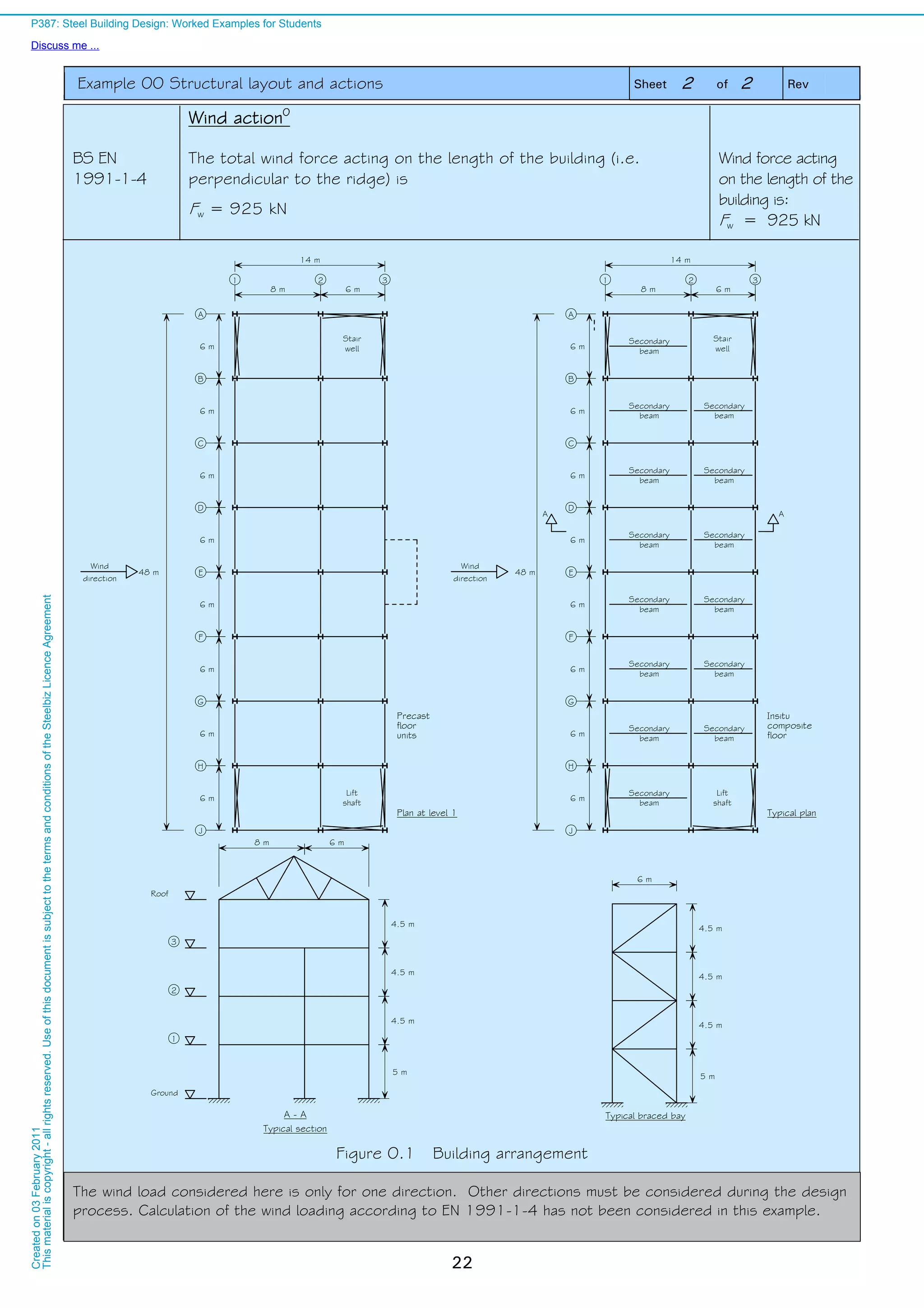


![Example 02 Simply supported unrestrained beam Sheet 4 of 6 Rev
32
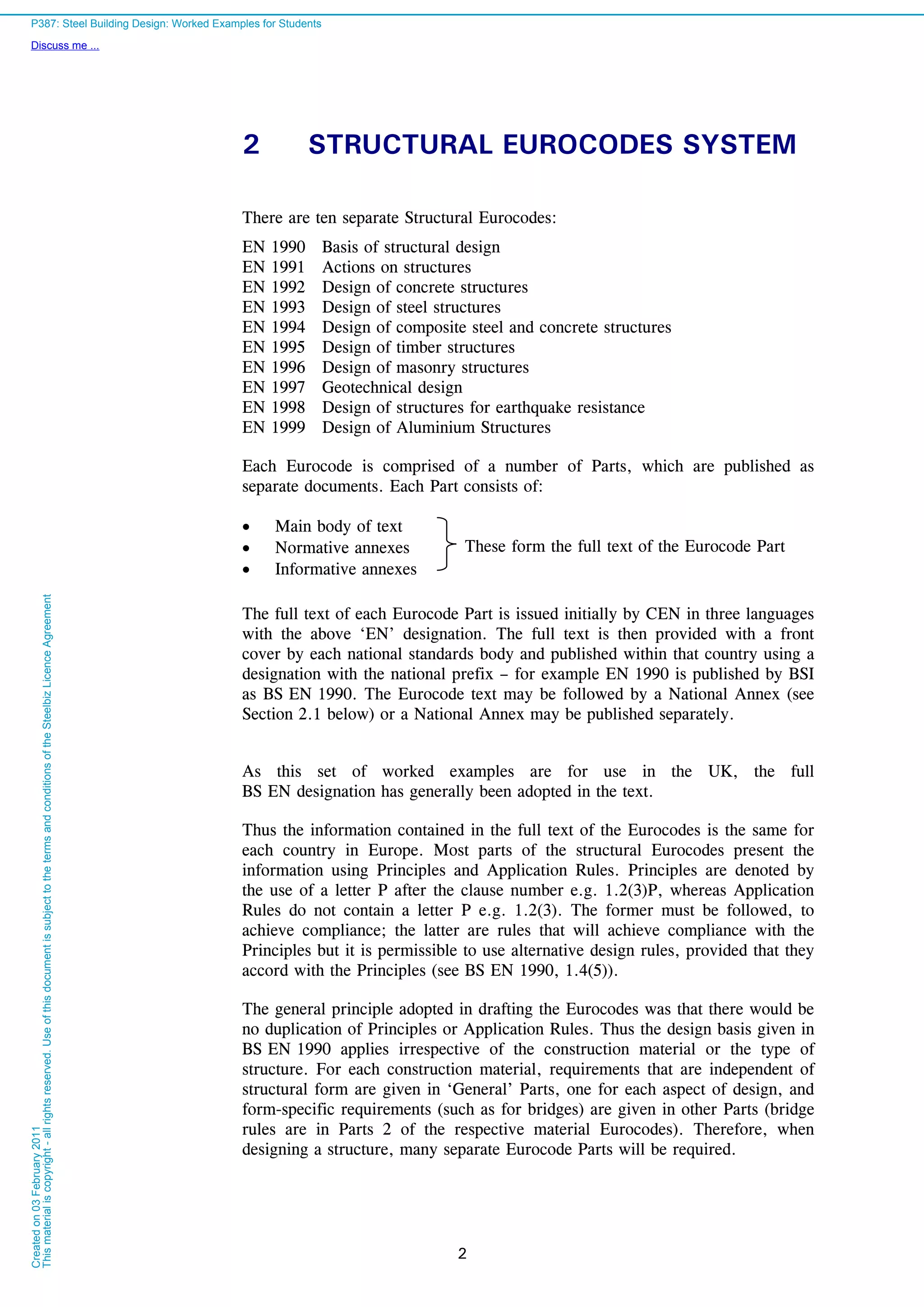
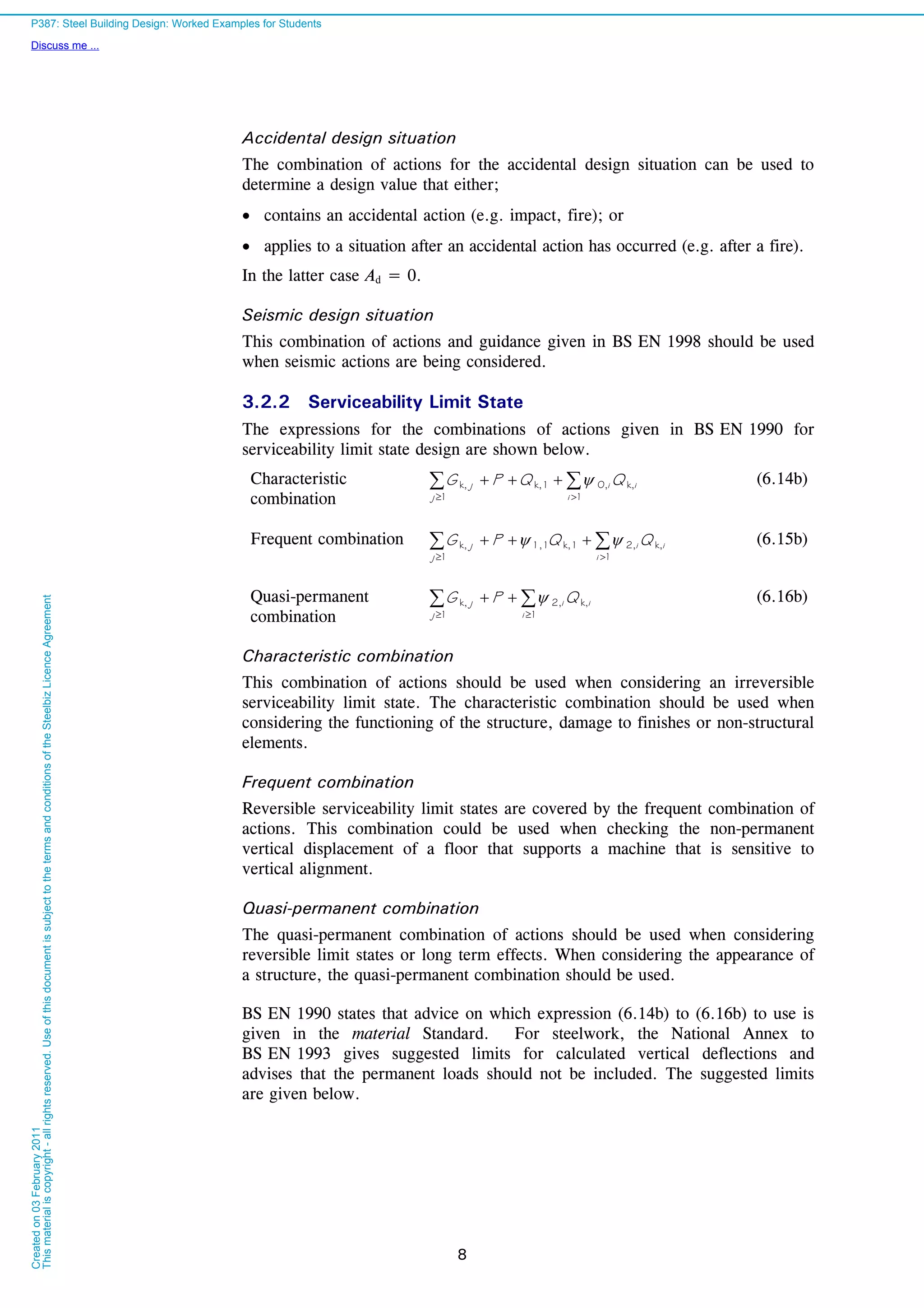
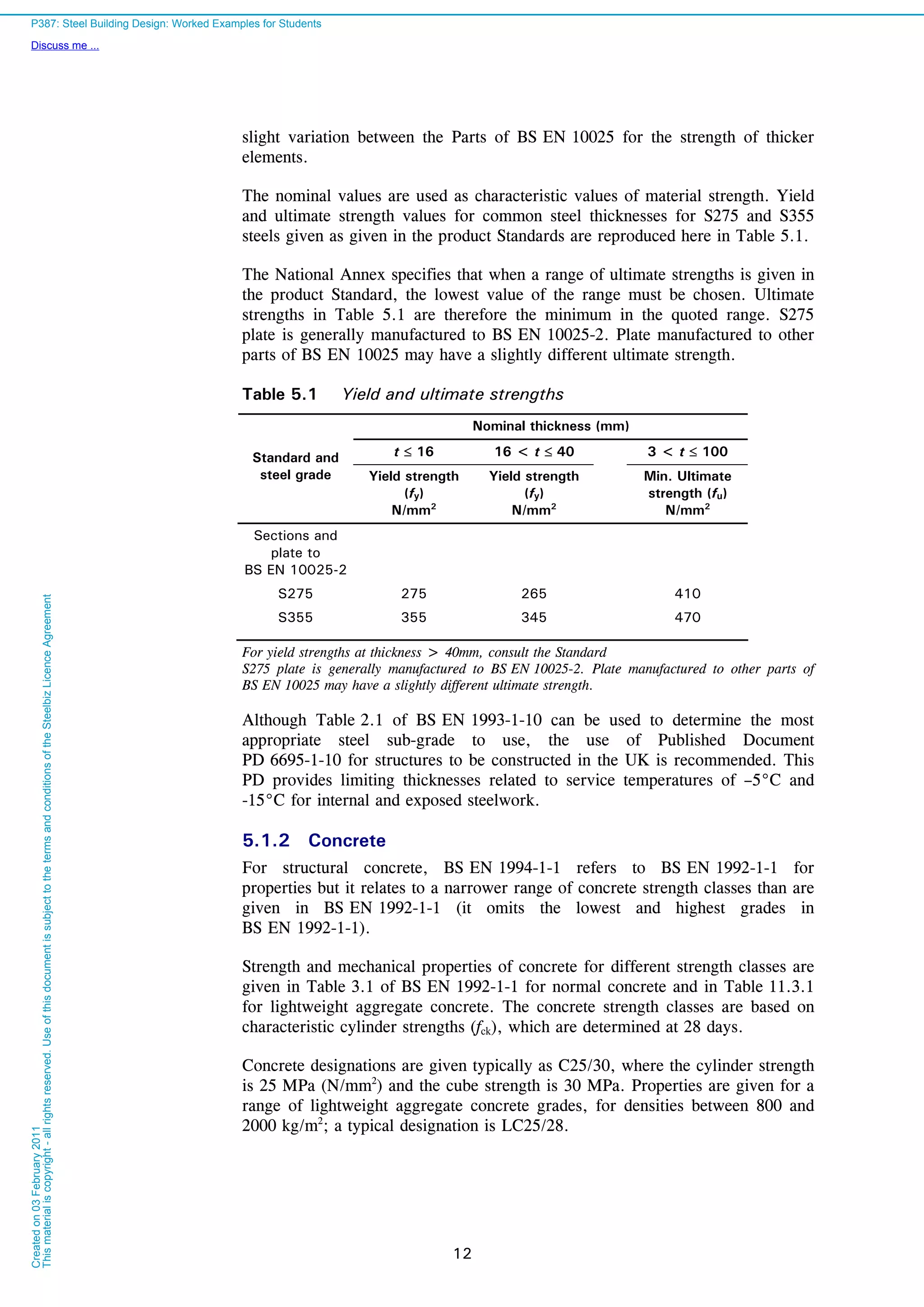
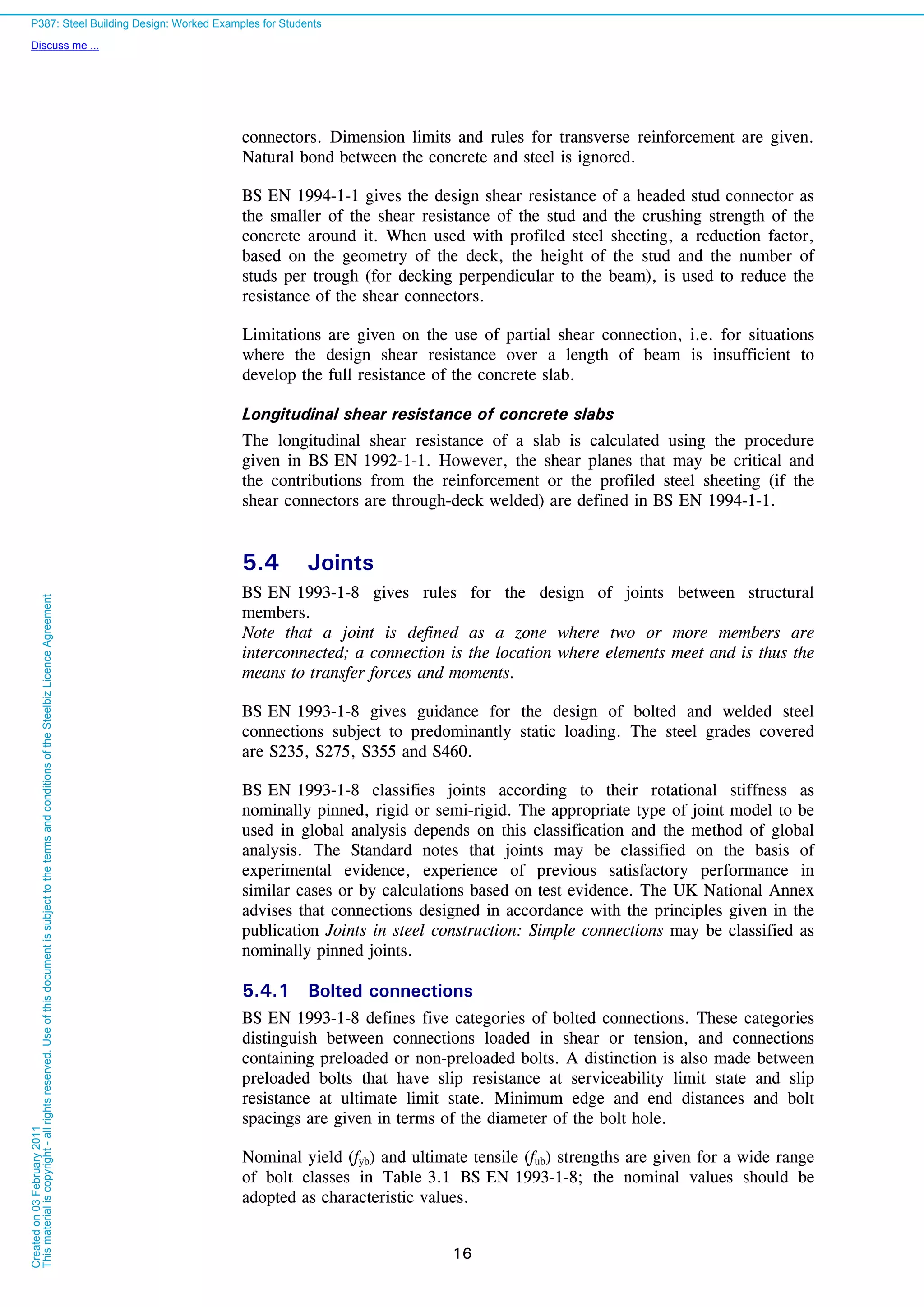
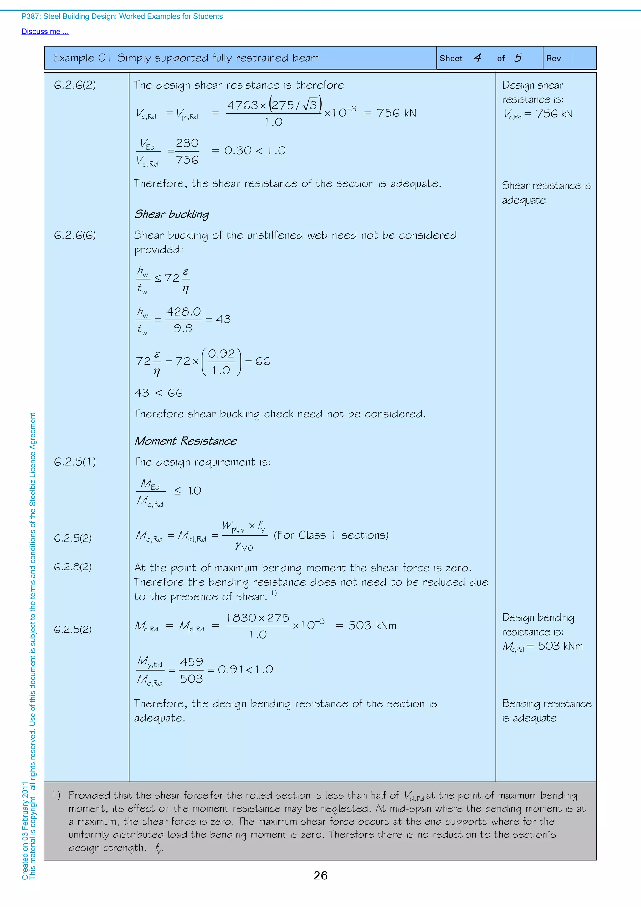
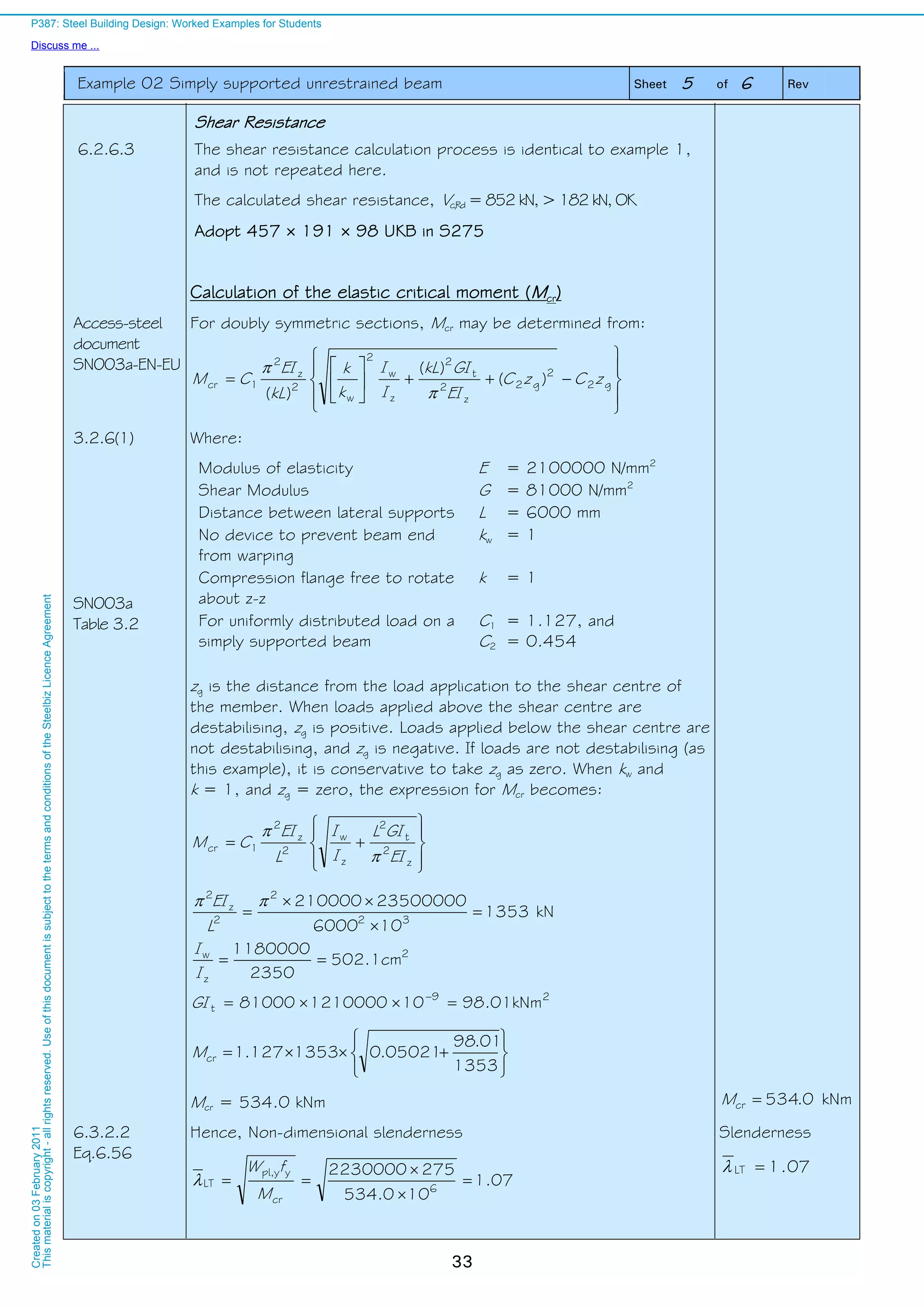
Reduction factor for lateral torsional buckling
6.3.2.3 For rolled I or H section, the reduction factor for torsional buckling
2
LT
2
LTLT
LT
1
but
2
LT
LT
LT
1
00,1
Where,
2
LTLT,0LTLTLT 10.5
6.3.2.3
NA 2.17
The value of LT,0 = 0.4 (maximum value)
The value of = 0.75 (minimum value)
NA 2.17
Table 6.3
For rolled Section with 42.2
8.192
2.467
b
h
and 3.1 2.42 > 2.0,
the buckling curve should be c, and imperfection factor LT = 0.49
Hence, the value for LT is:
LT = 0.5 [1+0.49 × (1.33 – 0.4) + 0.75 × 1.332
] = 1.391 LT = 1.391
Eq.6.57 Reduction factor
461.0
33.175.0391.1391.1
1
22
LT
Check: 00.1461.0LT
461.0LT 565.033.111 22
LT
So, reduction factor, LT = 0.461 Reduction factor,
LT = 0.461
Modification of LT for moment distribution
NA 2.18
P362
Correction factor due to UDL; 94.0
C
1
1
c k
])8.0(0.21)[1(5.01 2
LTc kf but 1.0
987.0])8.033.1(0.21)[94.01(5.01 2
6.3.2.3
Eq.6.58
Modified reduction factor
467.0
987.0
461.0LT
modLT,
f
Modified Reduction
factor
467.0mod,LT
Design buckling resistance moment of the unrestrained beam
6.3.2.1
Eq.6.55
M1
yypl,
LTRdb,
fW
M = 6
10
0.1
2652230000
467.0
= 276 kNm Buckling Resistance
Mb,Rd = 276 kNm
6.3.2.1
Eq.6.54 0.199.0
276
274
Rdb,
Ed
M
M
OK
Buckling resistance
adequate
P387: Steel Building Design: Worked Examples for Students
Discuss me ...
Createdon03February2011
Thismaterialiscopyright-allrightsreserved.UseofthisdocumentissubjecttothetermsandconditionsoftheSteelbizLicenceAgreement](https://image.slidesharecdn.com/steelbuildingdesignworkedexample-161119070745/75/Steel-building-design-worked-example-38-2048.jpg)
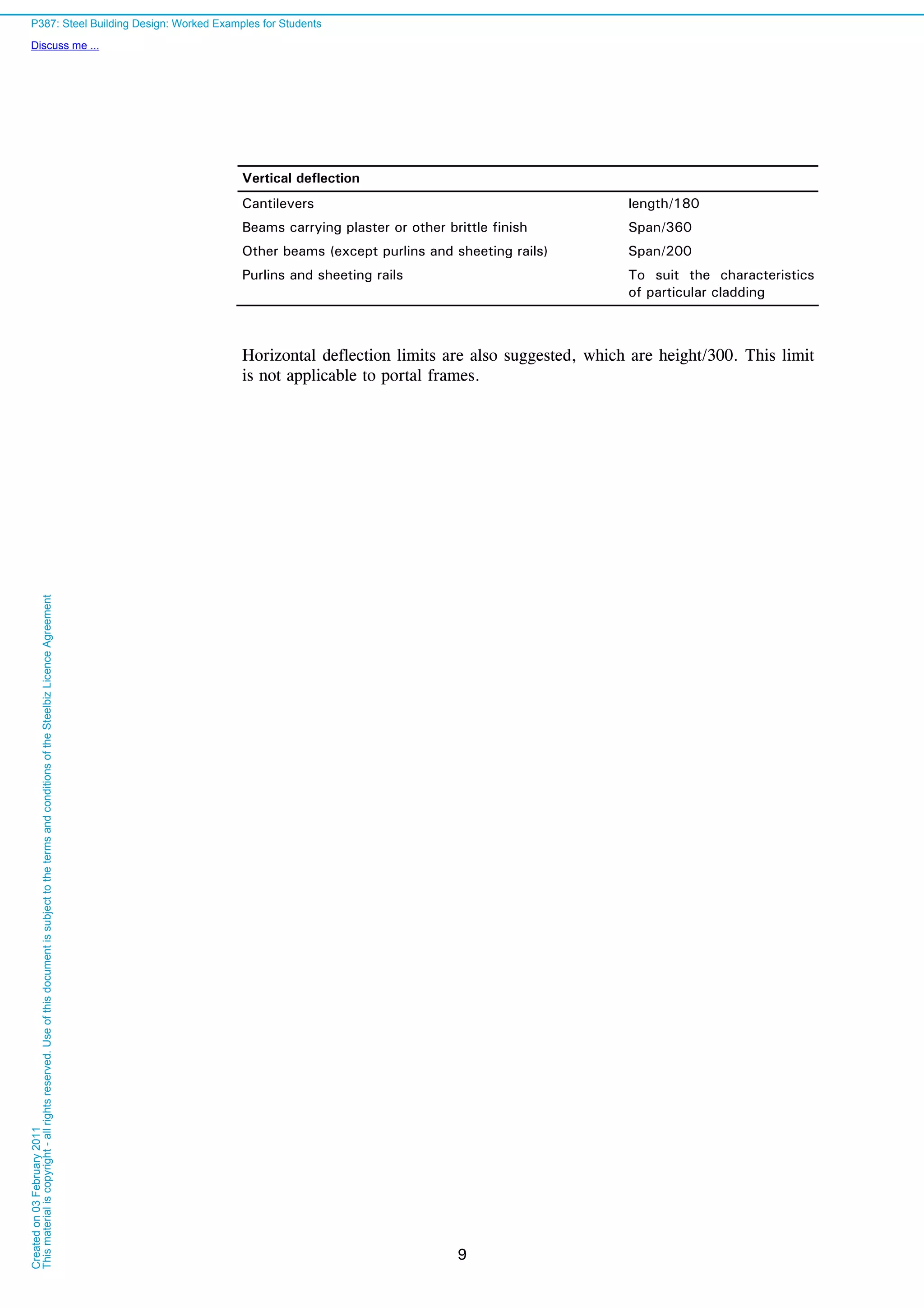
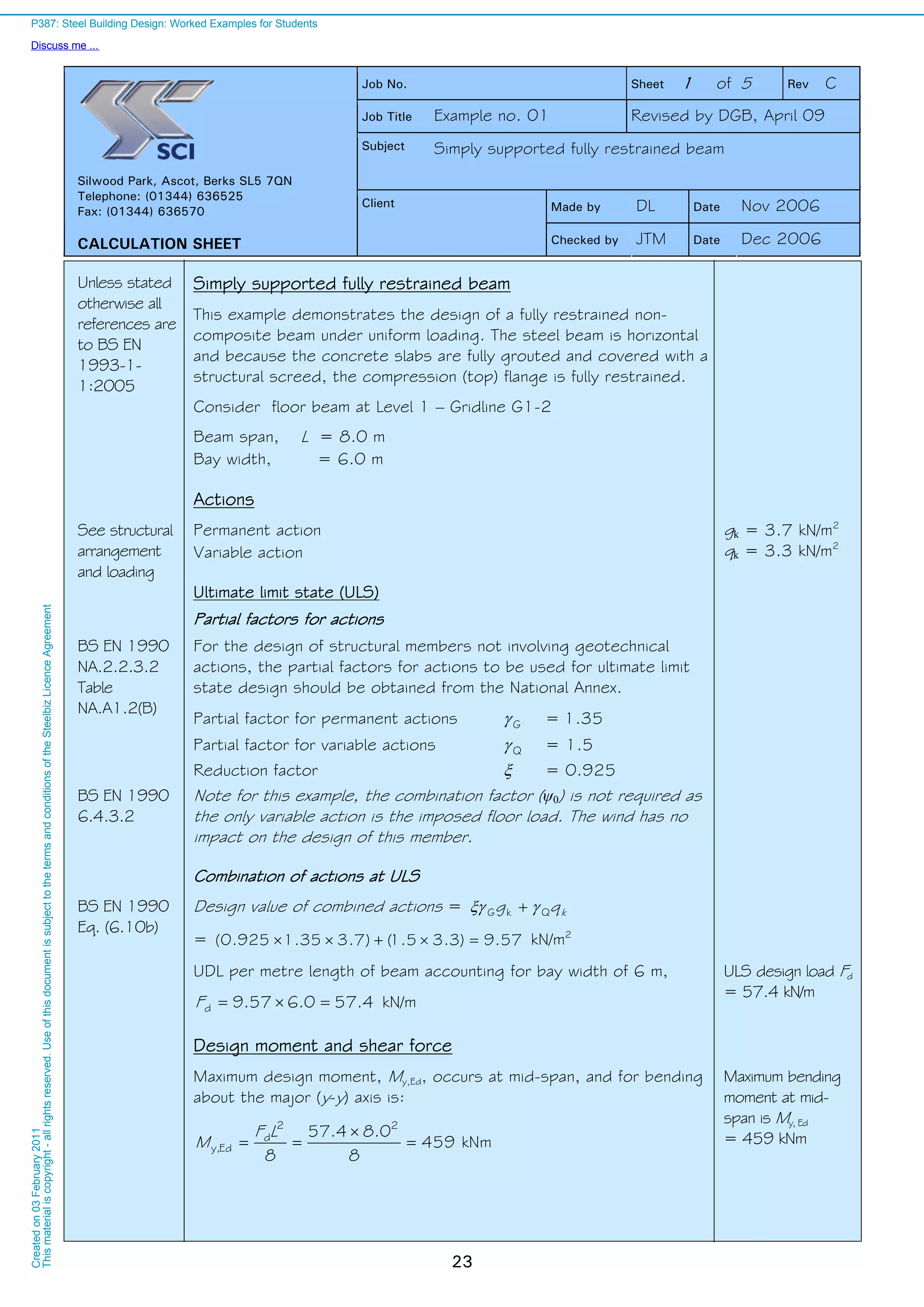
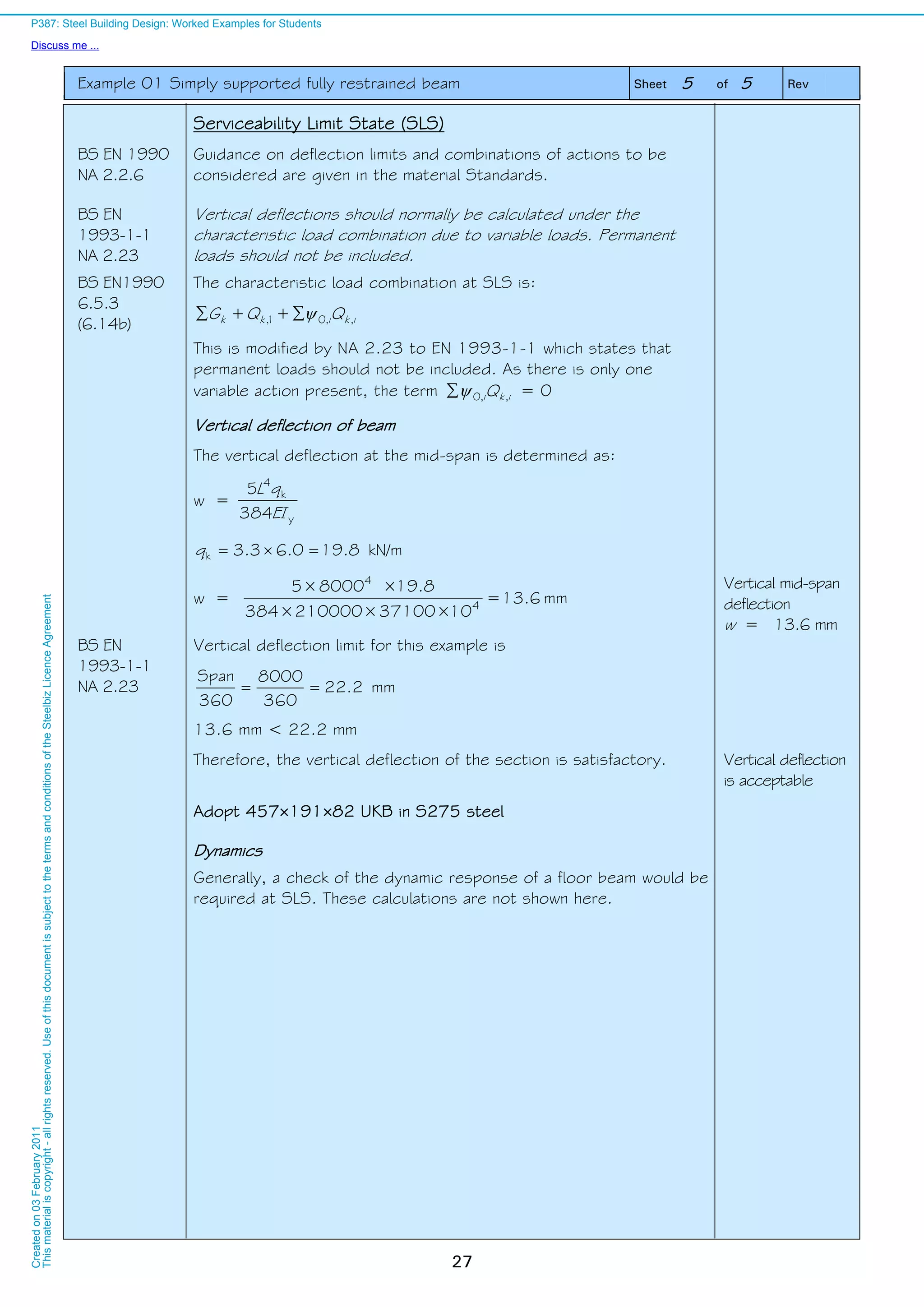
![Example 02 Simply supported unrestrained beam Sheet 6 of 6 Rev
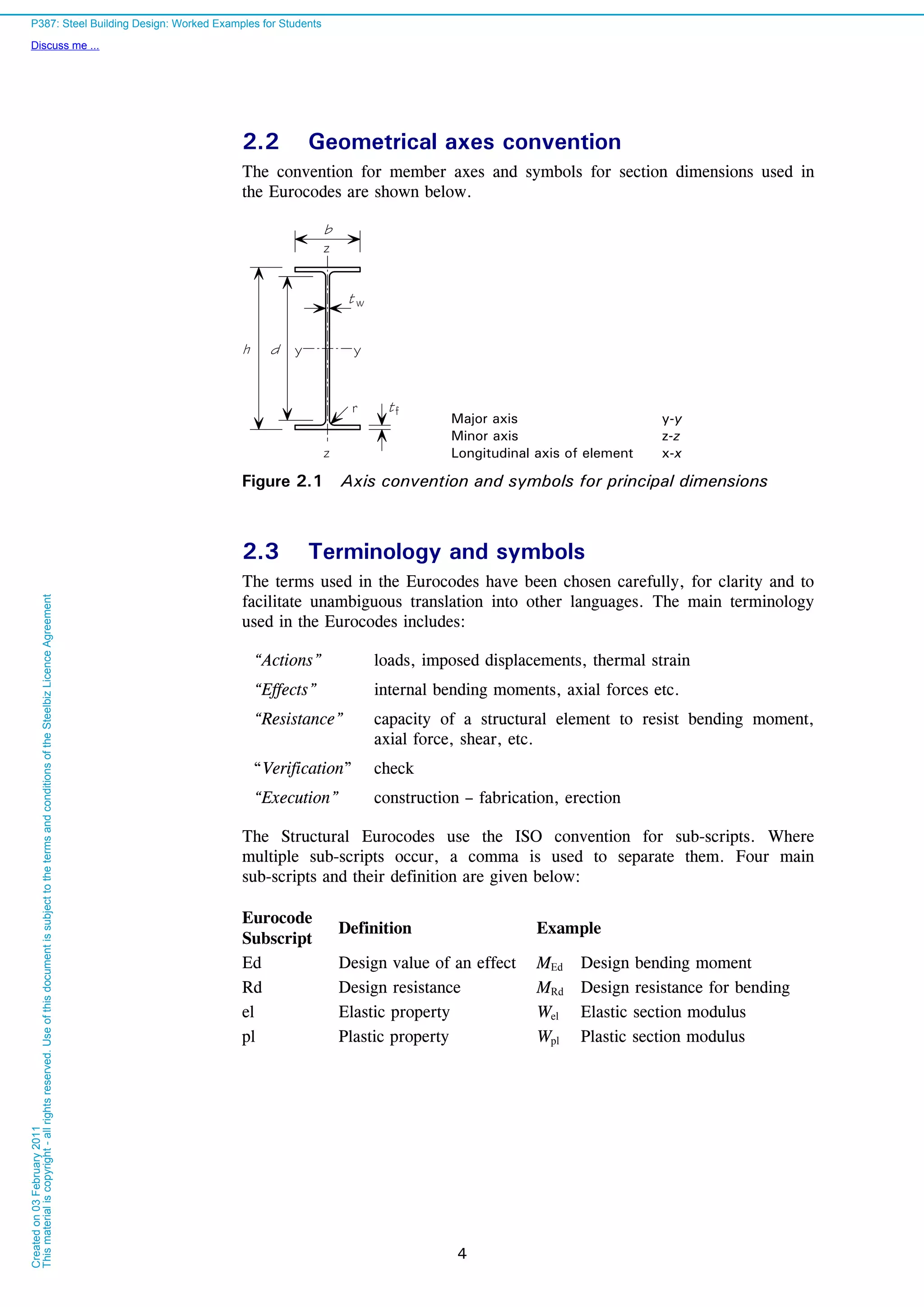
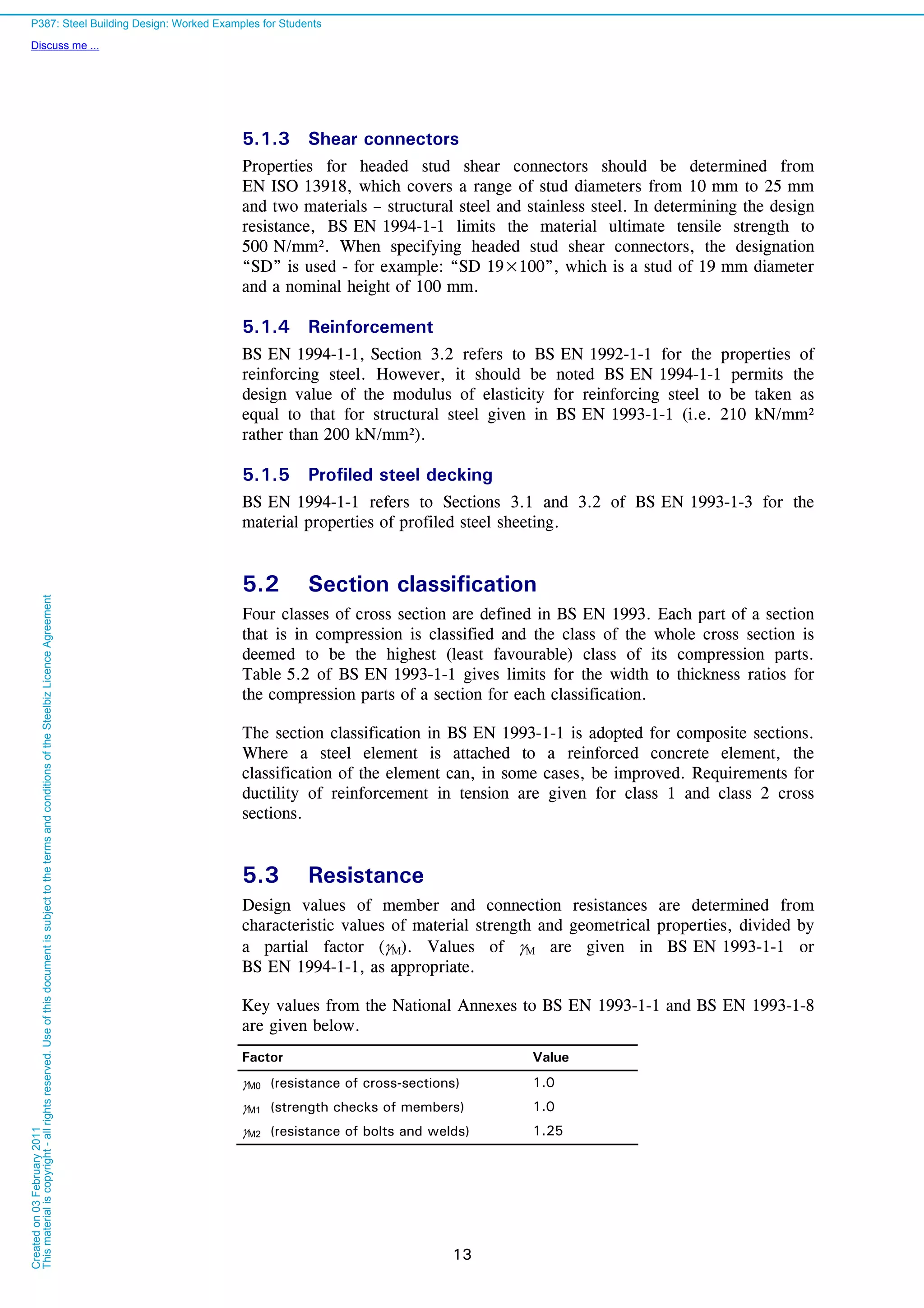
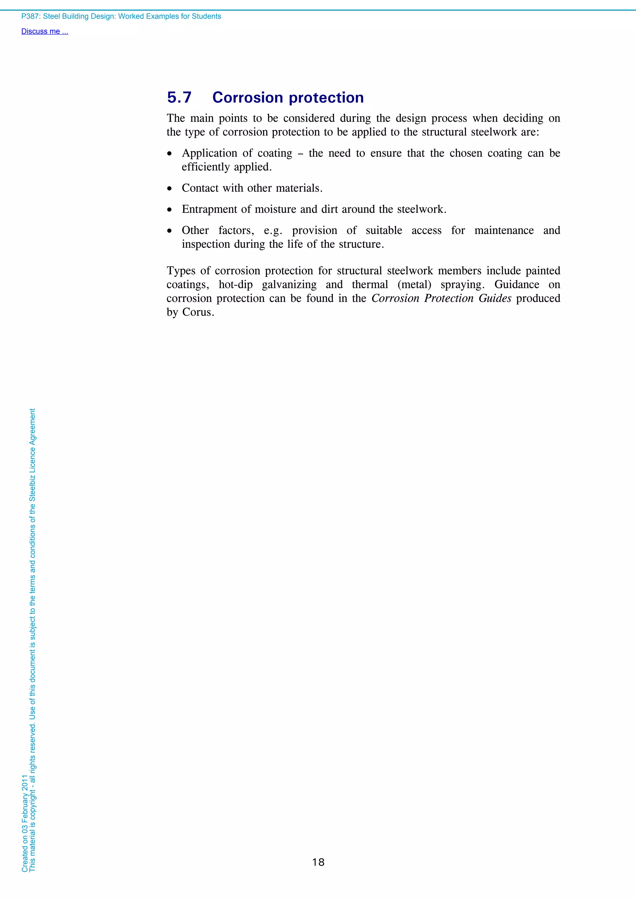
34
LT = 0.5 [1+0.49(1.07 – 0.4) + 0.75 × 1.072
] = 1.09
LT =
22
07.175.009.109.1
1
= 0.601
f = 1- 0.5 (1 – 0.94)[1- 2.0(1.07 – 0.8)2
] = 0.974
modLT, = 617.0974.0
601.0
M1
yy,pl
LTRdb,
fW
M
= 6
10
0.1
2652230000
617.0
= 365 kNm
Buckling
Resistance
Mb,Rd = 365 kNm
This example demonstrates that the simple approach based on
wz
1
LT 9.0
1
C
can produce significant conservatism
compared to the Mcr calculation process. (276 kNm compared to
365 kNm)
Serviceability Limit State (SLS) verification
No SLS checks are shown here; they are demonstrated in
Example 01.
P387: Steel Building Design: Worked Examples for Students
Discuss me ...
Createdon03February2011
Thismaterialiscopyright-allrightsreserved.UseofthisdocumentissubjecttothetermsandconditionsoftheSteelbizLicenceAgreement](https://image.slidesharecdn.com/steelbuildingdesignworkedexample-161119070745/75/Steel-building-design-worked-example-40-2048.jpg)
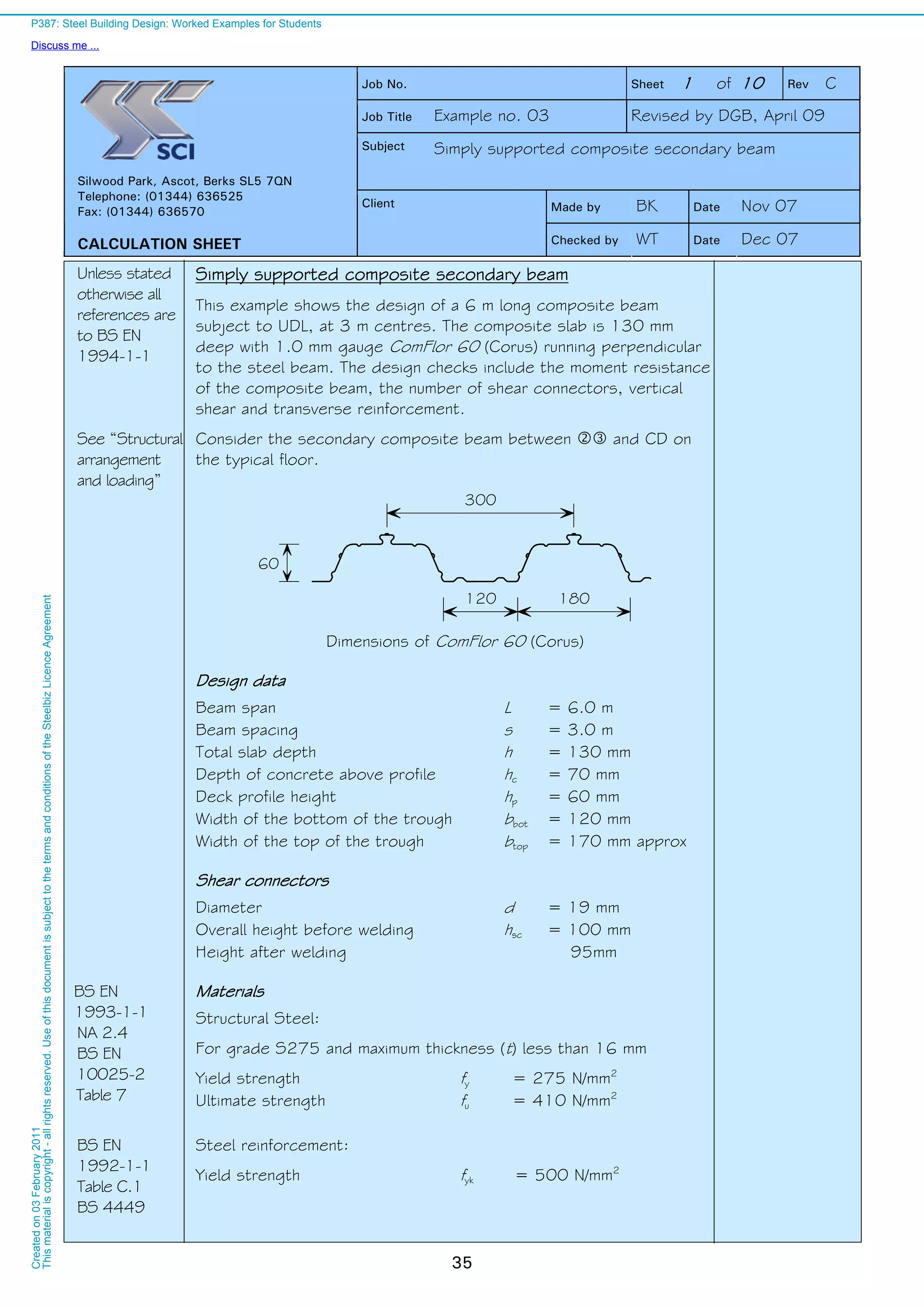
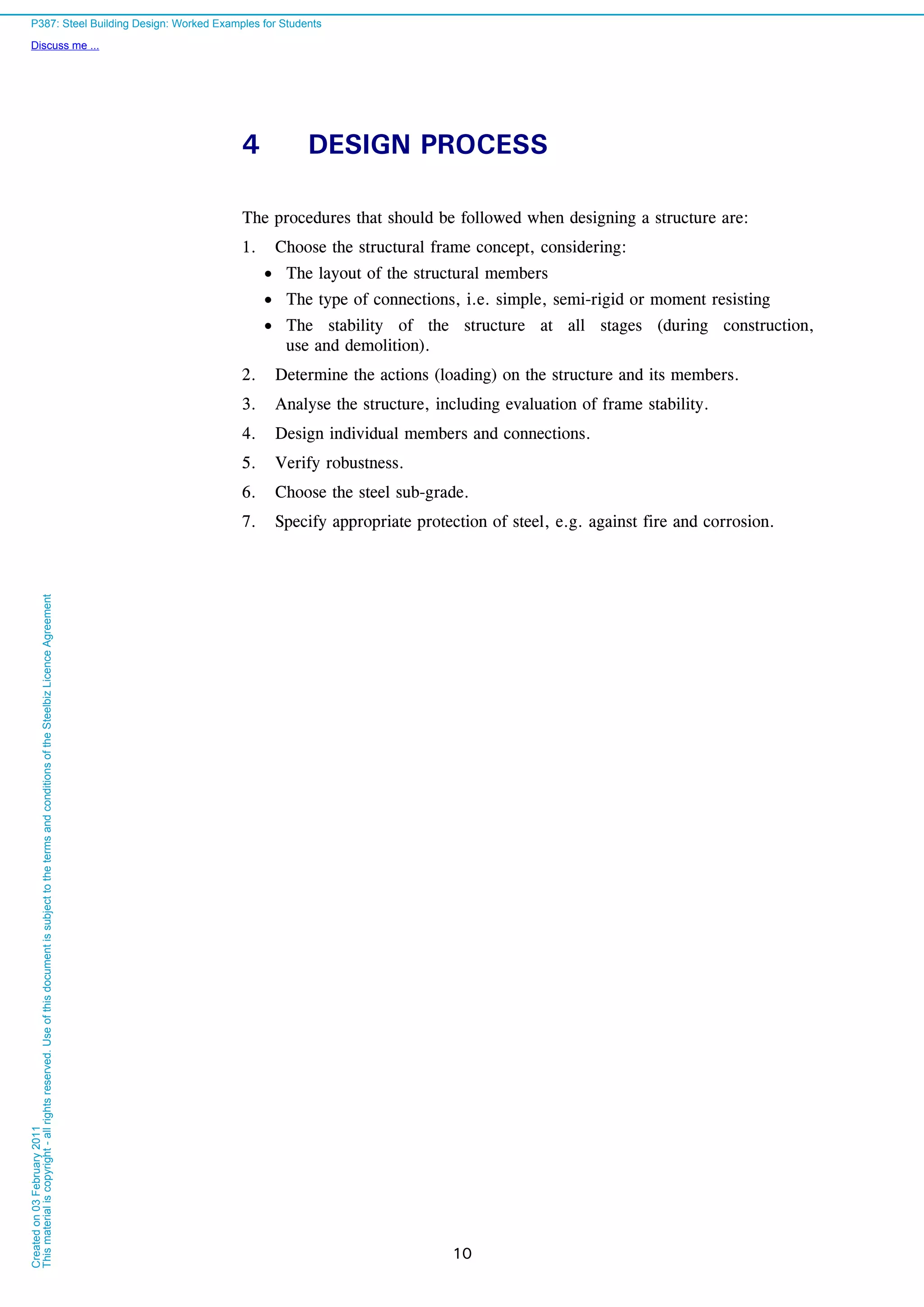
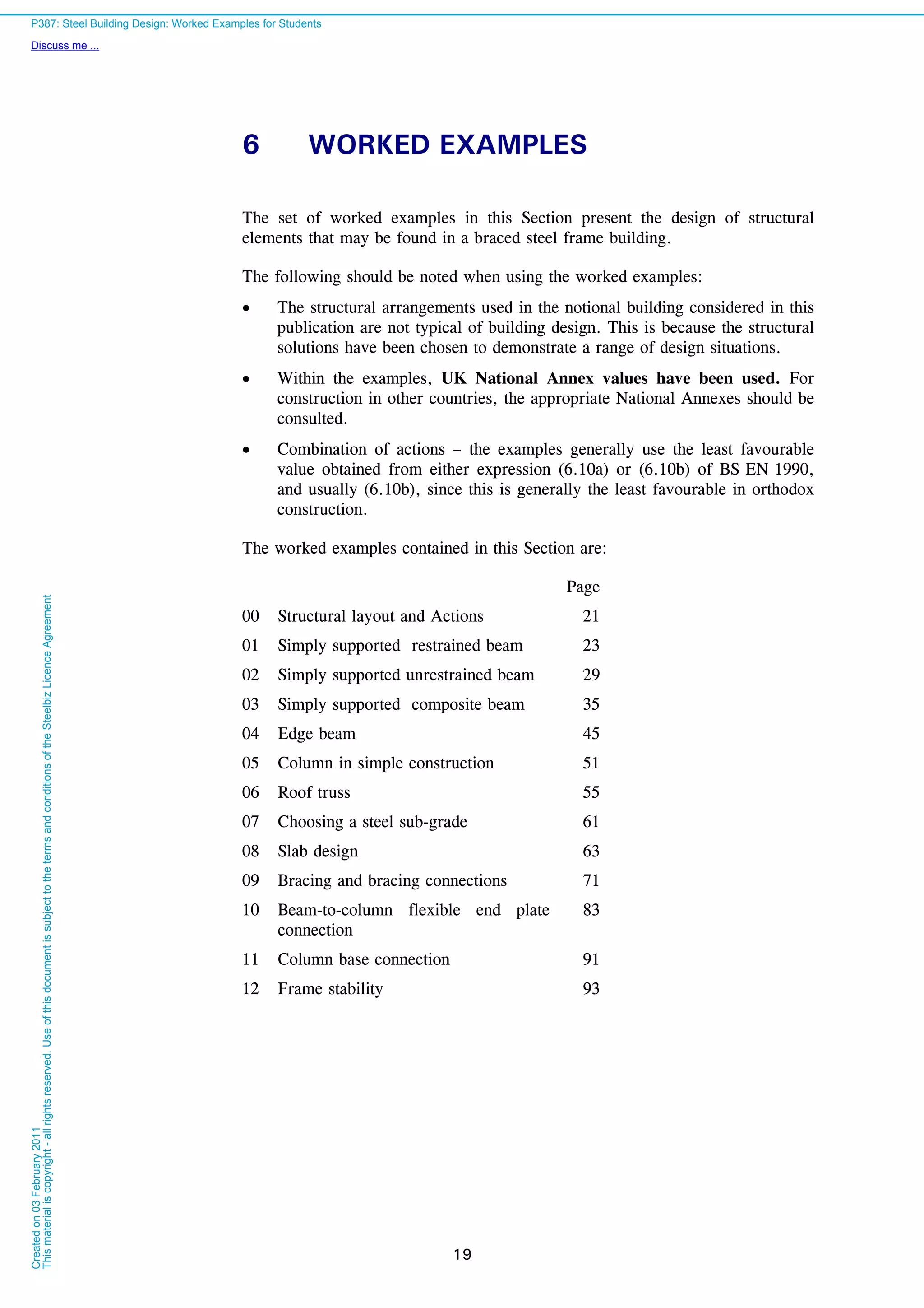
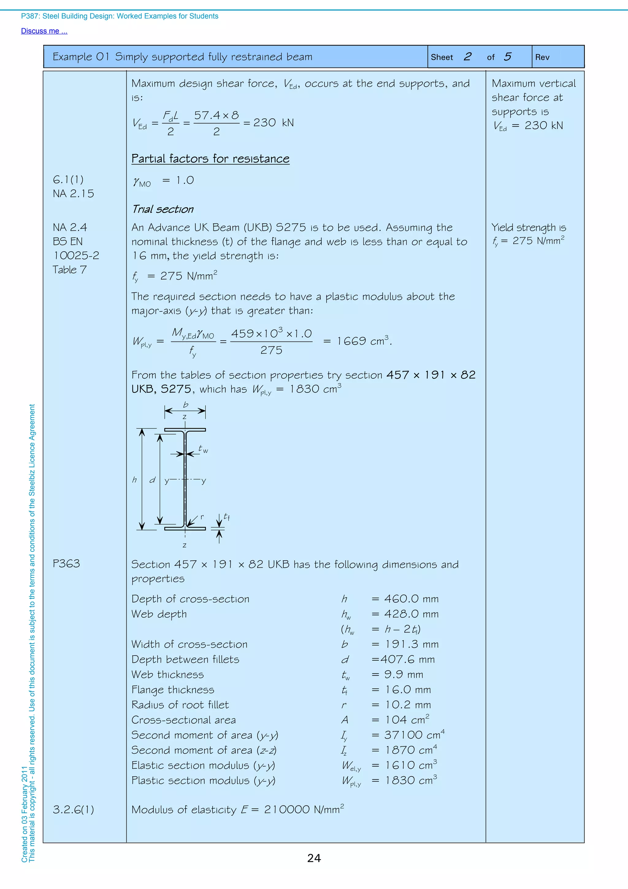
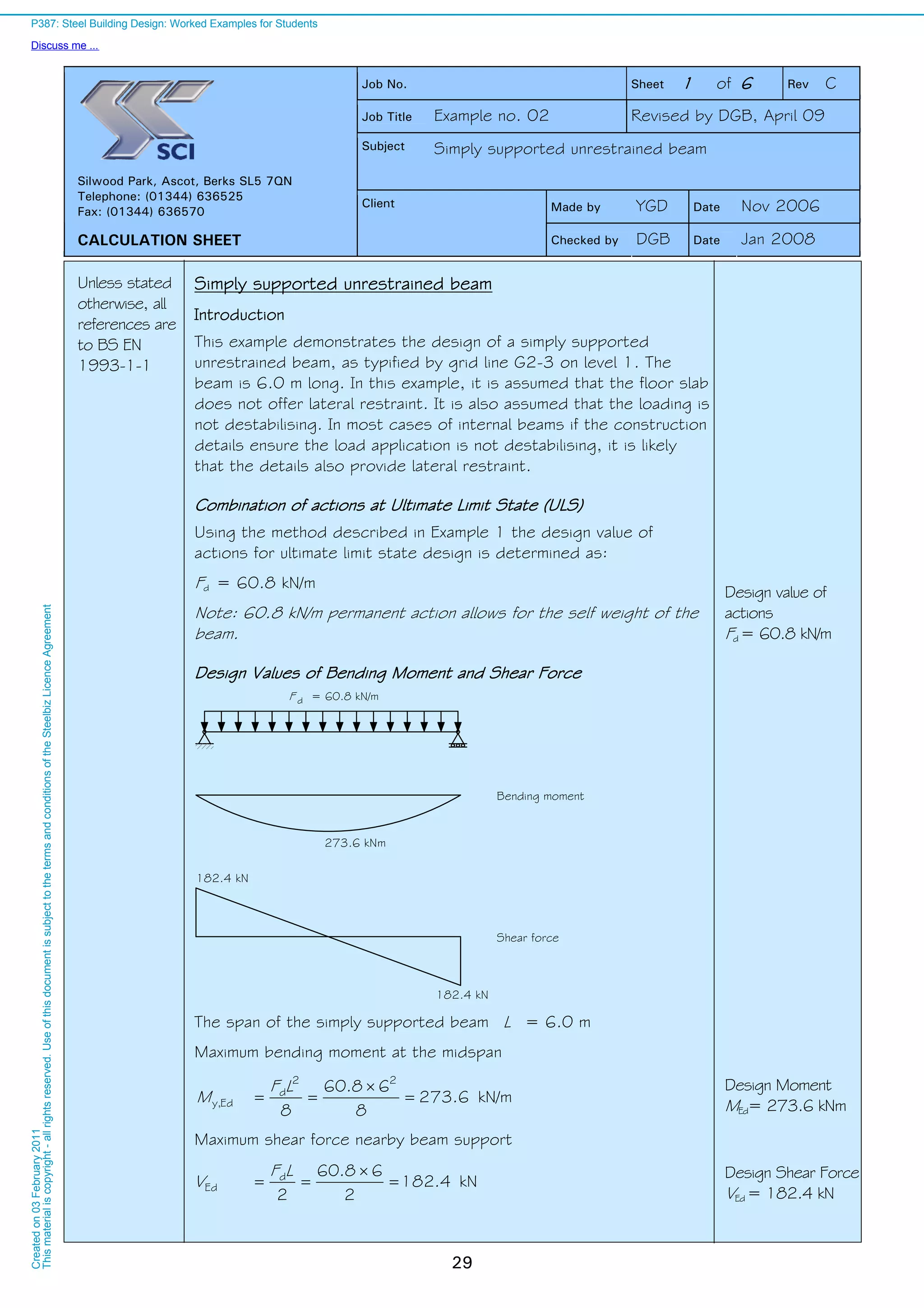
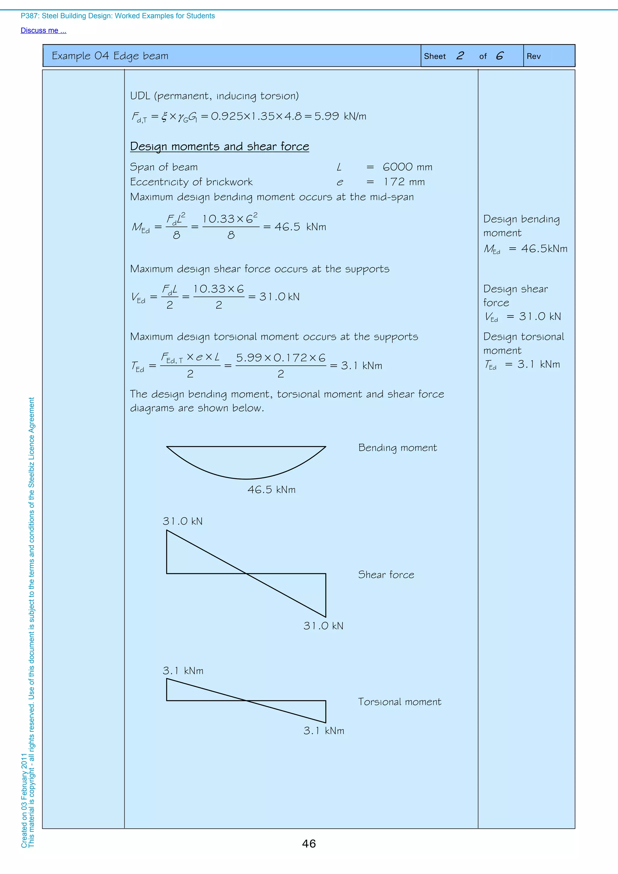
![Example 03 Simply supported composite secondary beam Sheet 2 of 10 Rev
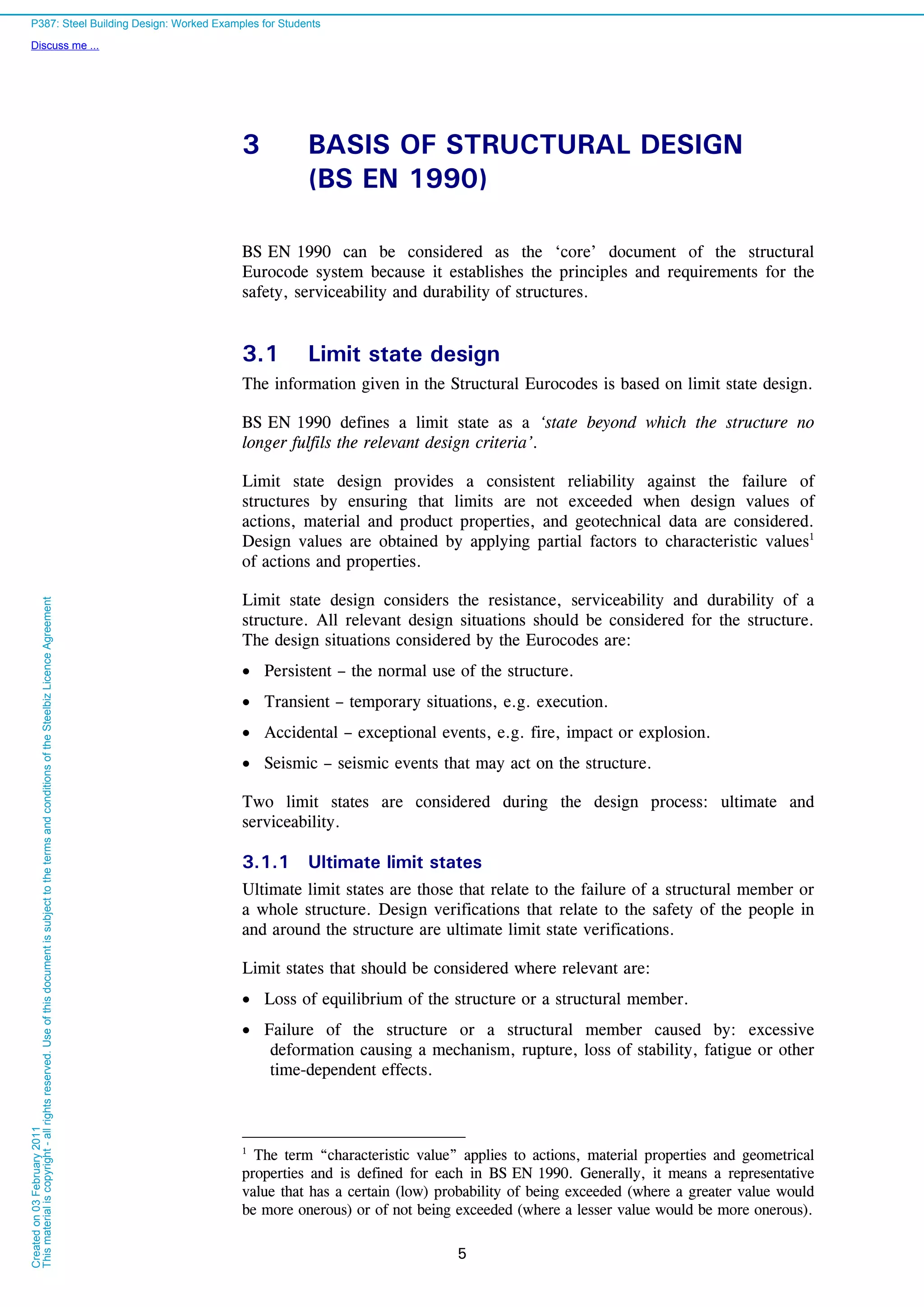
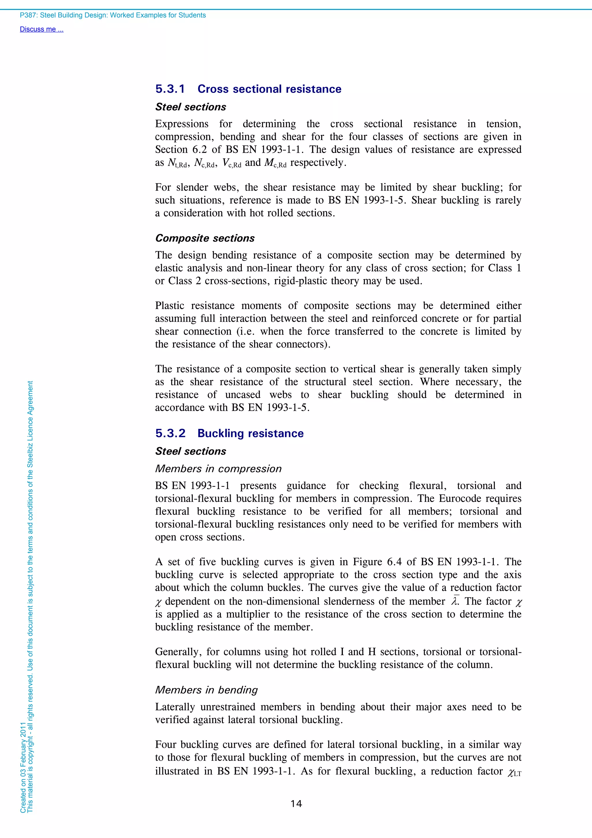
36
BS EN
1992-1-1
Table 3.1
Concrete:
Normal weight concrete strength class C25/30
Density 26 kN/m³ (wet)
25 kN/m³ (dry)
[These density values may vary for a specific project depending on the
amount of steel reinforcement.]
Cylinder strength fck = 25 N/mm2
Secant modulus of elasticity Ecm = 31 kN/mm2
Actions
Concrete weight
Self weight of the concrete slab (volume from manufacturer’s data)
52.21026097.0 6
kN/m2
(wet)
43.21025097.0 6
kN/m2
(dry)
Permanent actions
Construction stage kN/m2
Steel deck 0.11
Steel beam 0.20
Total 0.31
Composite stage kN/m2
Concrete slab 2.43
Steel deck 0.11
Steel beam 0.20
Ceiling and services 0.15
Total 2.89
Permanent
Construction stage:
gk = 0.31 kN/m2
Composite stage:
gk = 2.89 kN/m2
Variable actions Variable
BS EN
1991-1-6
NA 2.13
Construction stage kN/m2
Construction loading1)
(1) Inside and outside the
working area 0.75
(3) Concrete slab 2.52
Total 3.27
Composite stage kN/m2
Floor load 3.30
(See structural arrangement and
actions)
Construction stage:
qk = 3.27 kN/m2
Composite stage:
qk = 3.30 kN/m2
Ultimate Limit State
Combination of actions for Ultimate Limit State
BS EN 1990
Eqn 6.10b
NA 2.2.3.2
Table
NA A1.2(B)
The design value of combined actions are :
Construction stage:
Distributed load (0.925×1.35×0.31)+(1.5×3.27) = 5.29 kN/m2
Total load 2.950.30.626.5d F kN
Composite stage:
Distributed load (0.925×1.35×2.89)+(1.5×3.3) = 8.56 kN/m2
Total load 0.1530.30.656.8d F kN
Construction stage
Fd = 95.2 kN
Composite stage
Fd = 153.0 kN
1) Note that the allowance of 0.75 kN/m2
is deemed appropriate in this example, in accordance with NA 2.13 of
BS EN 1991-1-6.
P387: Steel Building Design: Worked Examples for Students
Discuss me ...
Createdon03February2011
Thismaterialiscopyright-allrightsreserved.UseofthisdocumentissubjecttothetermsandconditionsoftheSteelbizLicenceAgreement](https://image.slidesharecdn.com/steelbuildingdesignworkedexample-161119070745/75/Steel-building-design-worked-example-42-2048.jpg)
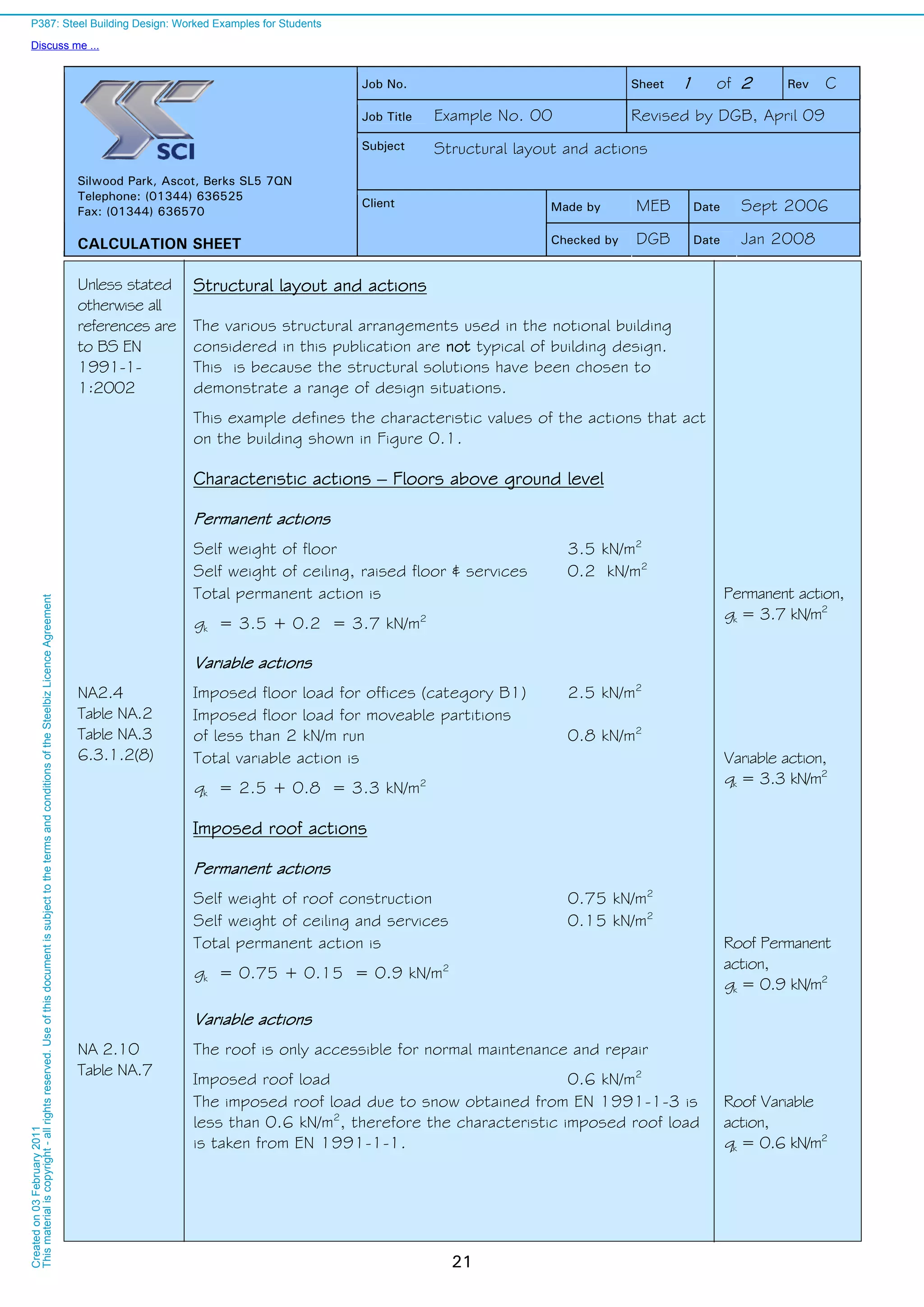
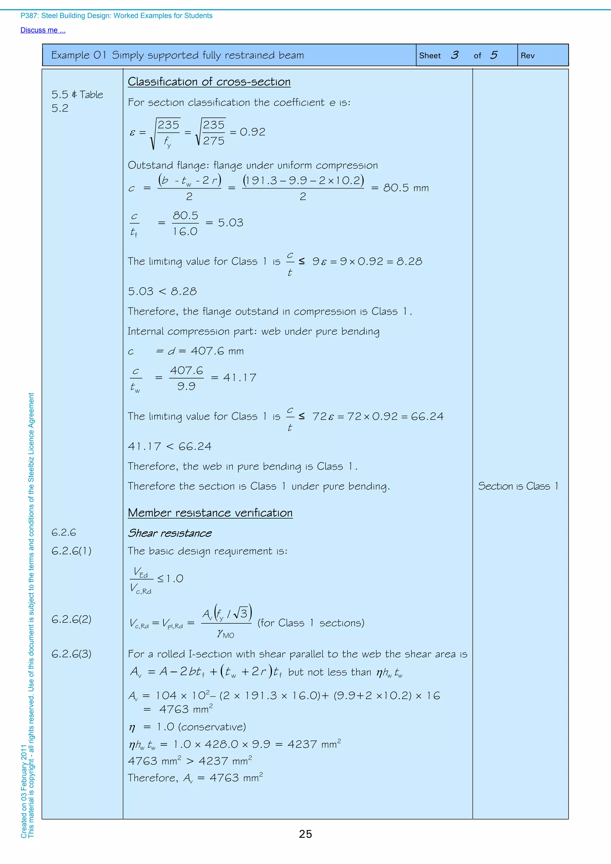
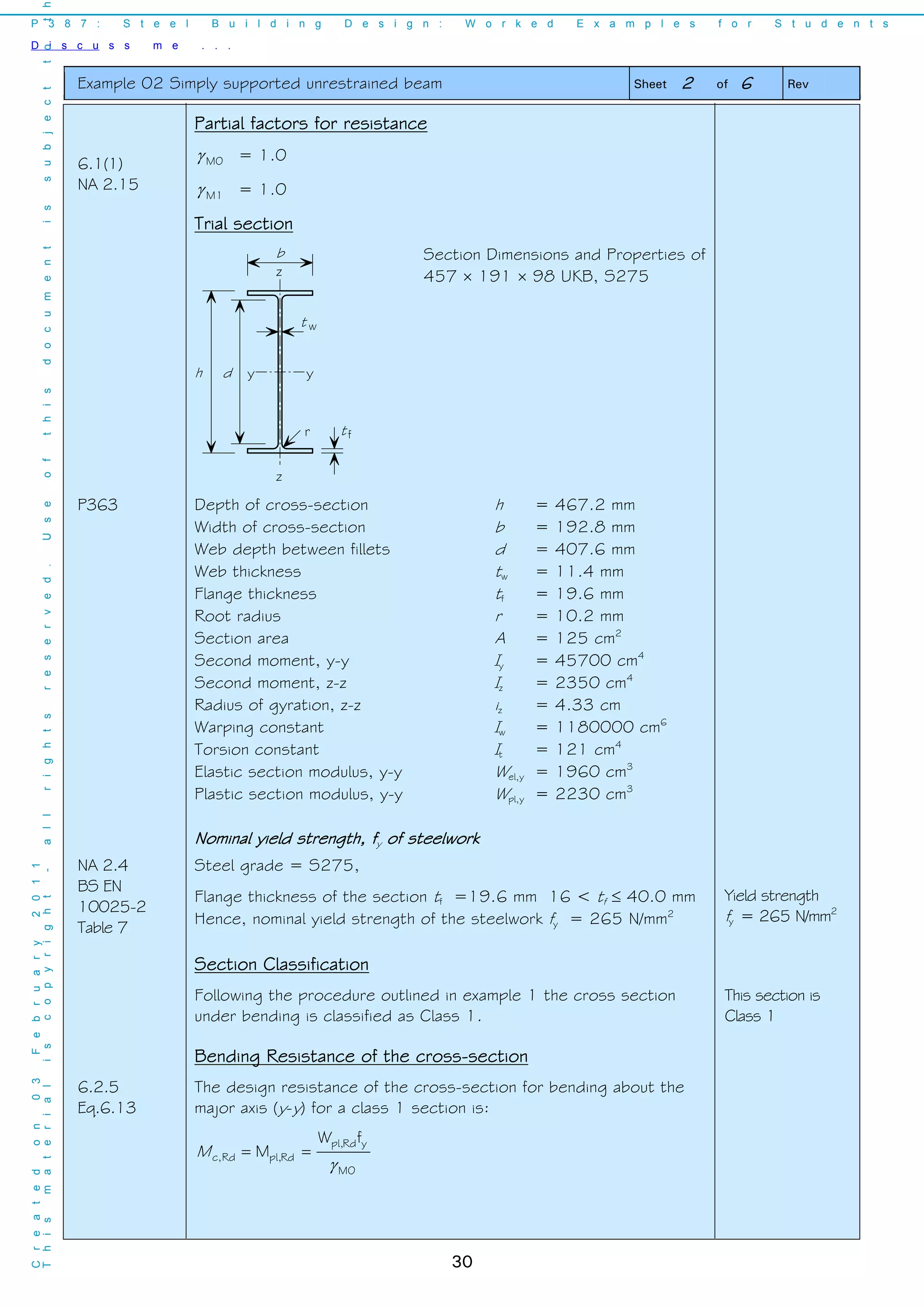
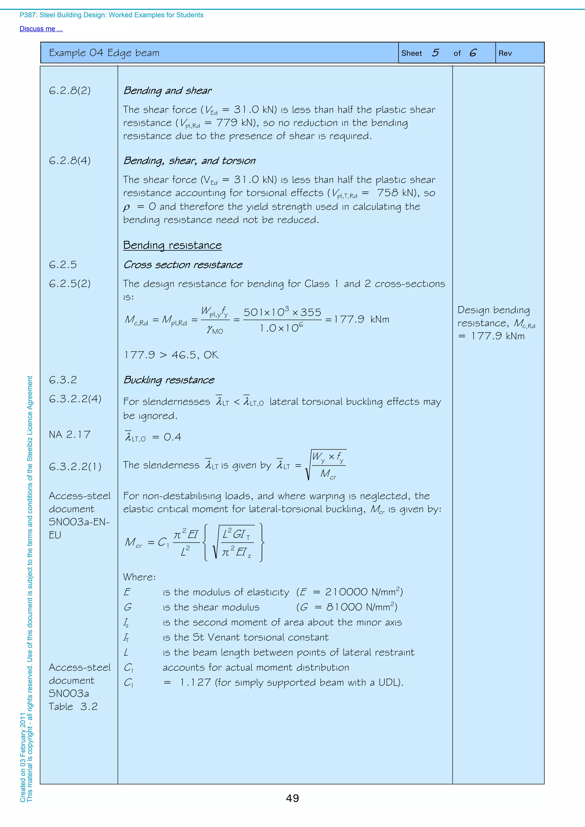
![Example 03 Simply supported composite secondary beam Sheet 3 of 10 Rev
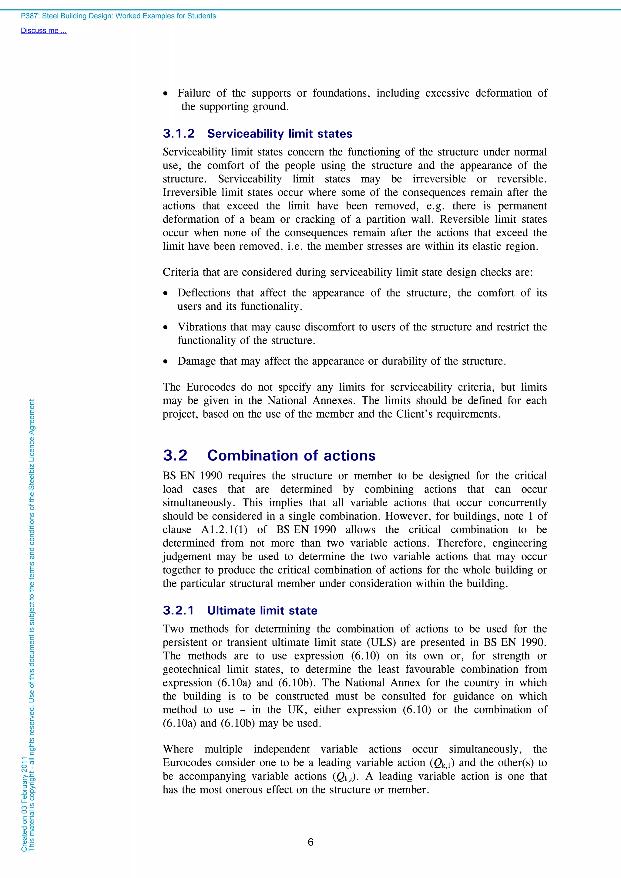
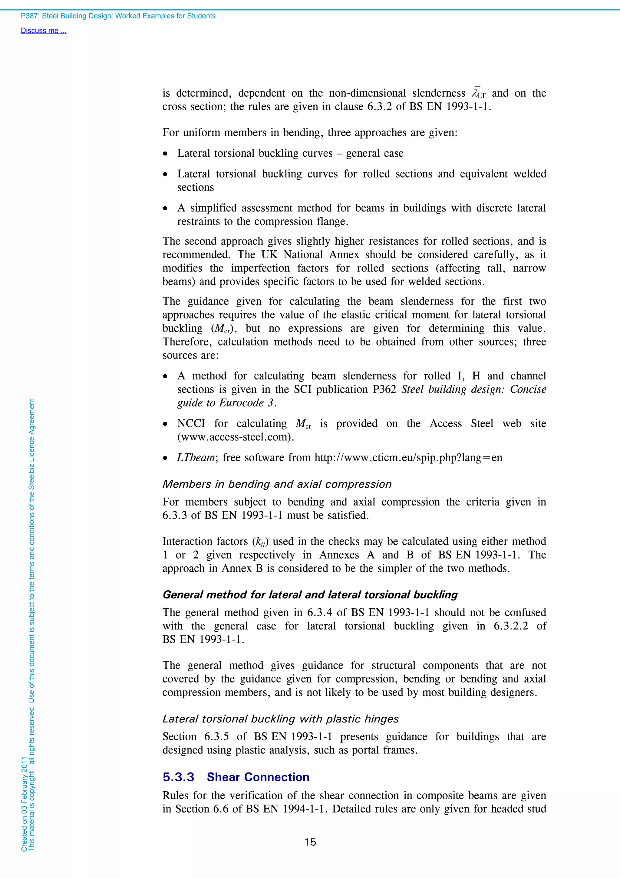
37
Design values of moment and shear force at ULS
Construction stage
Maximum design moment (at mid span)
4.71
8
0.62.95
8
d
Edy,
LF
M kNm
Construction stage:
My,Ed = 71.4 kNm
Composite stage
Maximum design moment (at mid span)
8.114
8
0.60.153
8
d
Edy,
LF
M kNm
Maximum design shear force (at supports)
5.76
2
0.153
2
d
Ed
F
V kN
Composite stage:
My,Ed = 114.8 kNm
VEd = 76.5 kN
BS EN
1993-1-1
NA 2.15
BS EN
1992-1-1
NA 2
Table NA.1
NA 2.3
NA 2.4
Partial factors for resistance
Structural steel M0 = 1.0
Concrete C = 1.5
Reinforcement S = 1.15
Shear connectors V = 1.25
[Note that the National Annex states that the recommended value of V
should be adopted in the absence of more specific information for the type
of decking being used. For simplicity, the recommended value of V is used
in this example.]
Longitudinal shear VS = 1.25
Trial section
The plastic modulus that is required to resist the construction stage
maximum design bending moment is determined as:
Wpl,y =
275
0.1104.71 3
y
M0Edy,
f
M
= 259 cm3
From the tables of section properties try
section 254 102 22 UKB, S275, which has Wpl,y = 259 cm3
My,Ed
My,Ed
VEd
VEd
P387: Steel Building Design: Worked Examples for Students
Discuss me ...
Createdon03February2011
Thismaterialiscopyright-allrightsreserved.UseofthisdocumentissubjecttothetermsandconditionsoftheSteelbizLicenceAgreement](https://image.slidesharecdn.com/steelbuildingdesignworkedexample-161119070745/75/Steel-building-design-worked-example-43-2048.jpg)
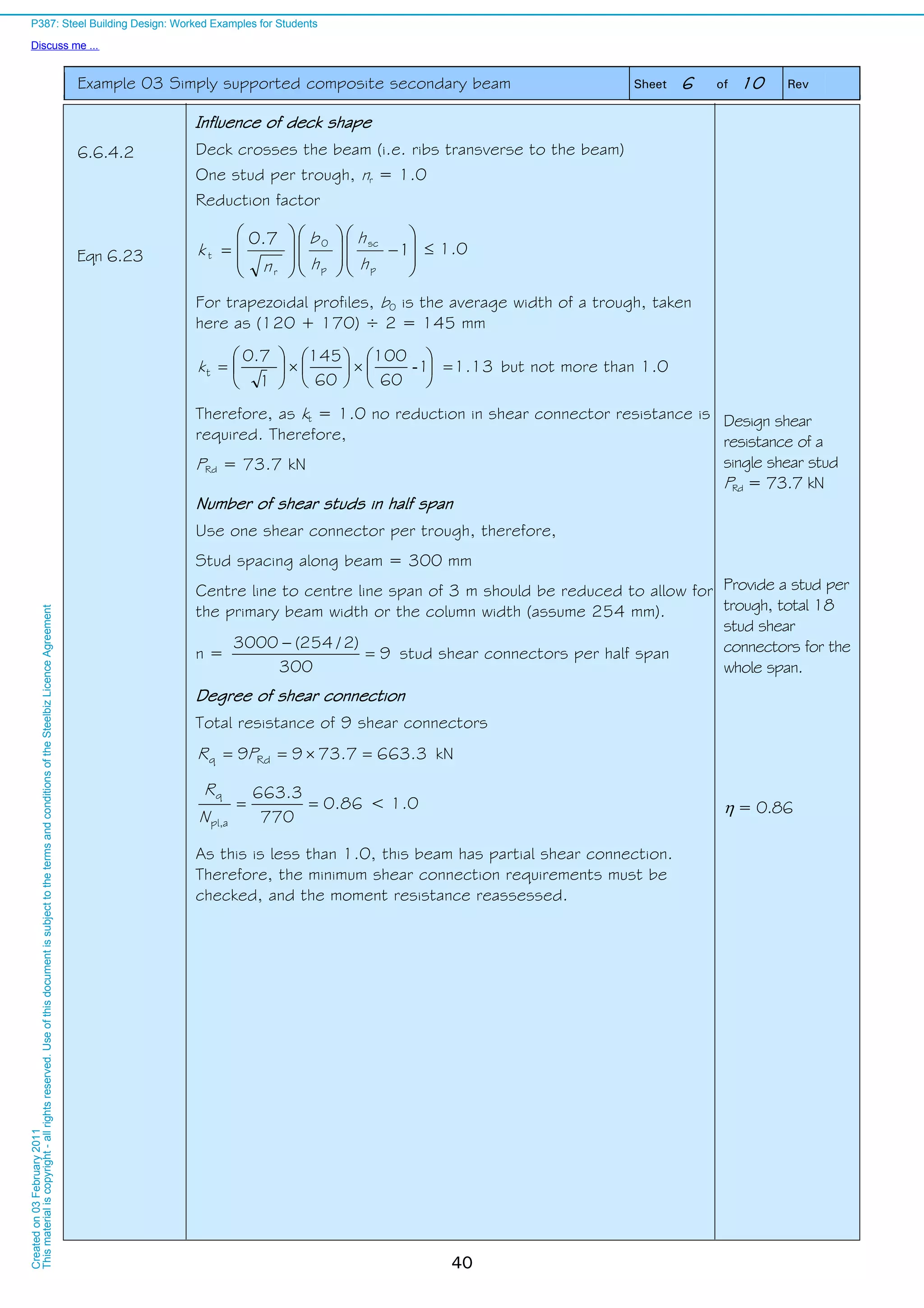
![Example 03 Simply supported composite secondary beam Sheet 4 of 10 Rev
38
P363 Depth of cross-section ha = 254.0 mm
Width of cross-section b = 101.6 mm
Depth between fillets d = 225.2 mm
Web thickness tw = 5.7 mm
Flange thickness tf = 6.8 mm
Radius of root fillet r = 7.6 mm
Cross-section area Aa = 28 cm2
[Note the subscript ‘a’ indicates the steel cross section. A subscript ‘c’
indicates concrete properties.]
Plastic section modulus (y-y) Wpl,y = 259 cm3
BS EN
1993-1-1
NA 2.4
tf < 16 mm, therefore fy = 275 N/mm2
BS EN
1993-1-1
3.2.6(1)
Modulus of elasticity E = 210000N/mm2
Section classification
The section is Class 1 under bending.2)
Note that other construction stage checks are not included in this
example.
Section is Class 1
Composite stage member resistance checks
Concrete
BS EN
1992-1-1
3.1.6
NA 2
Table NA 1
Design value of concrete compressive strength fcd = cc × fck / c
cc = 0.85
fcd = 0.85 × 25 / 1.5 = 14.2 N/mm2
fcd = 14.2 N/mm2
Compression resistance of concrete slab
5.4.1.2 At mid-span the effective width of the compression flange of the
composite beam is determined from:
ei0eff bbb
75.0
8
6
88
e
ei
LL
b m (Le = L for simply supported beams)
Assume a single line of shear studs, therefore, 00 b m
50.175.020eff b m < 3 m (beam spacing) Effective width
beff = 1.50 m
6.2.1.2 Compression resistance of concrete slab is determined from:
ceffcdslabc, hbfN
where hc is the depth of the solid concrete above the decking
1491107015002.14 3
slabc,
N kN
Design compressive
resistance of slab
Nc,slab = 1491 kN
2) See Example 01 for classification method.
P387: Steel Building Design: Worked Examples for Students
Discuss me ...
Createdon03February2011
Thismaterialiscopyright-allrightsreserved.UseofthisdocumentissubjecttothetermsandconditionsoftheSteelbizLicenceAgreement](https://image.slidesharecdn.com/steelbuildingdesignworkedexample-161119070745/75/Steel-building-design-worked-example-44-2048.jpg)


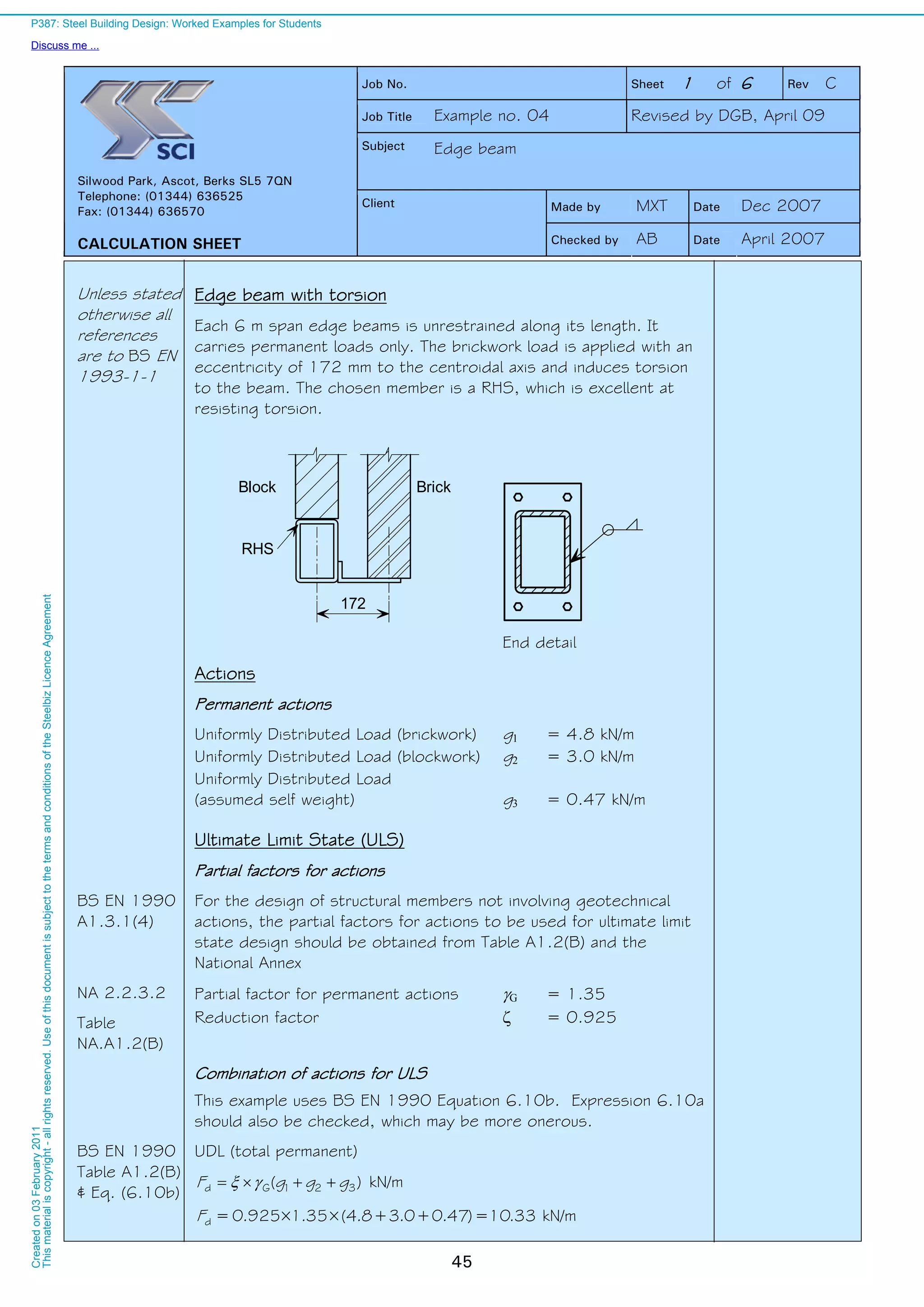


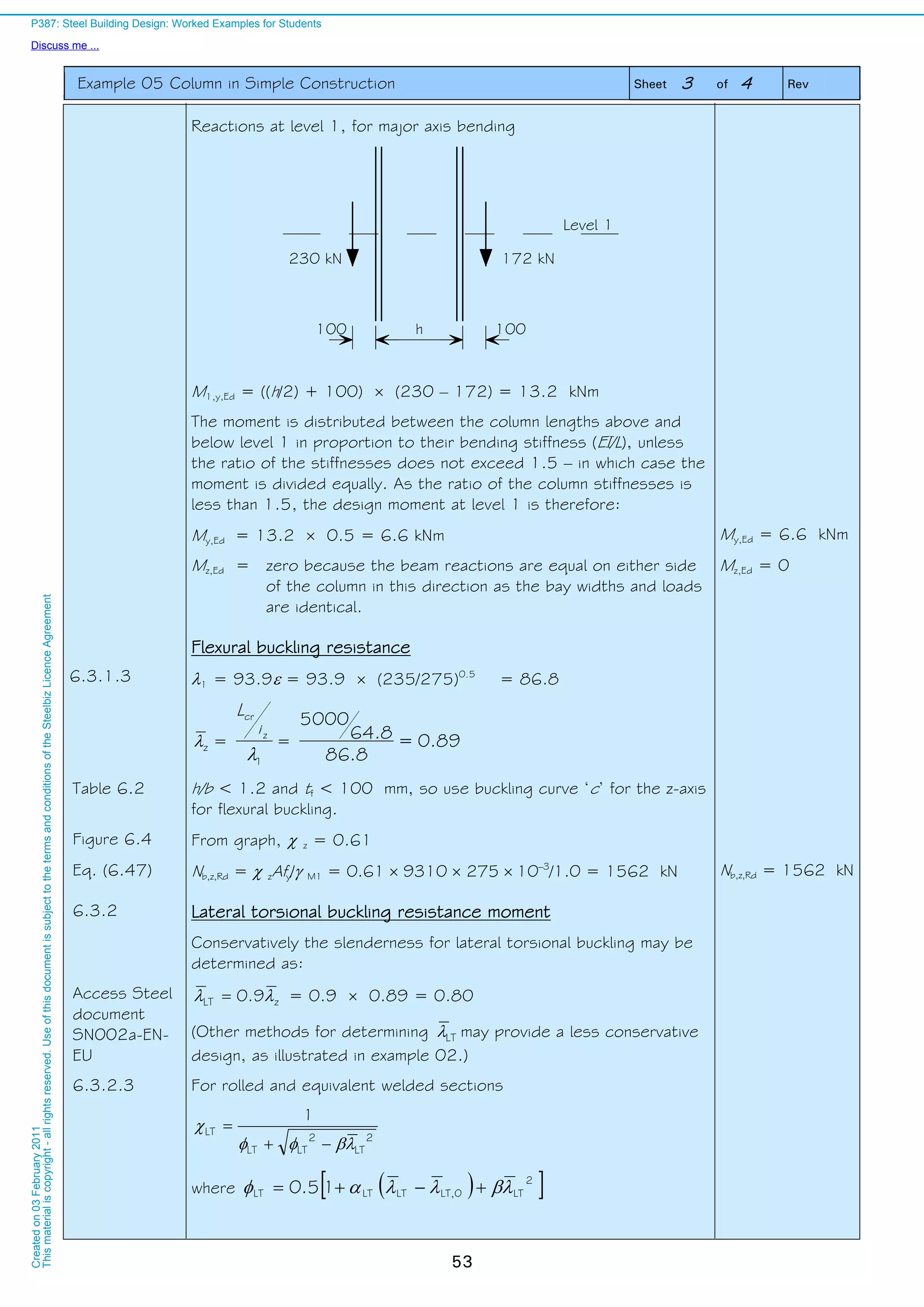


![Job No. Sheet 1 of 2 Rev C
Job Title Example no. 07 Revised by DGB, April 09
Subject Choosing a steel sub-grade
Made by LPN Date May 2007
Silwood Park, Ascot, Berks SL5 7QN
Telephone: (01344) 636525
Fax: (01344) 636570
CALCULATION SHEET
Client
Checked by MEB Date Jan 2008
61
Unless
stated
otherwise all
references
are to BS EN
1993-1-10
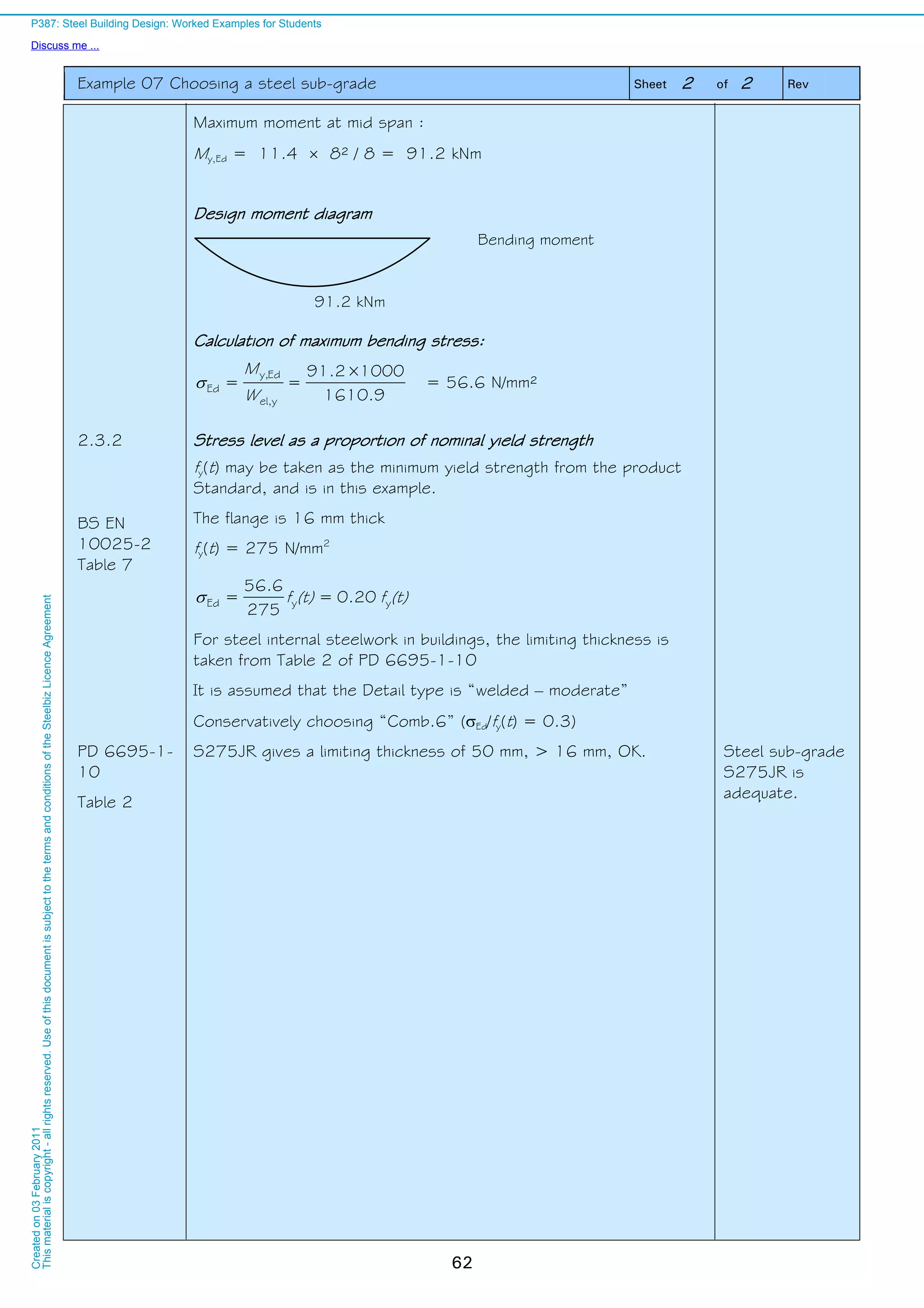
Choosing a steel sub-grade
Introduction
Determine the steel sub-grade that may be used for the simply
supported restrained beam (UKB 457 191 82 steel grade
S275).
The example follows the procedure recommended in
PD 6695-1-10. This published document provides non conflicting
complimentary information to the Eurocode, and presents a
straightforward approach to the choice of steel sub-grade.
Floor beam at Level 1 – Gridline G1-2
Beam span, L = 8.0m
Bay width, w = 6.0m
Actions
Permanent action : gk = 3.7 kN/m2
Variable action : qk = 3.8 kN/m2
SCI P363 Section Properties
From example 01:
Web thickness tw = 9.9 mm
Flange thickness tf = 16.0 mm
Elastic modulus, y-y Wel,y = 1610.9 cm3
Yield strength fy = 275 N/mm2
2.2.4 (i)
BS EN 1990
A.1.2.2 (1)
NA 2.2.2
Table
NA.A1.1
Combination of actions
Effects are combined according to the following expression:
Ed = E { A[TEd] "+" GK "+" 1 QK1 "+" 2,i QKi }
not relevant for this example as
there is only one variable action
where 1 = 0.5 (Category B: Office areas)
It is assumed that there are no locked in stresses due to
temperature, since bolts in clearance holes are used. Therefore
A[TEd] = 0
Design value of combined actions
GK1 + 1 QK = 0.5 3.8 6 = 11.4 kN/m
P 3 8 7 : S t e e l B u i l d
D i s c u s s m e . . .
Createdon03February2
Thismaterialiscopyrigh](https://image.slidesharecdn.com/steelbuildingdesignworkedexample-161119070745/75/Steel-building-design-worked-example-67-2048.jpg)

![Example 08 Composite slab Sheet 2 of 7 Rev
64
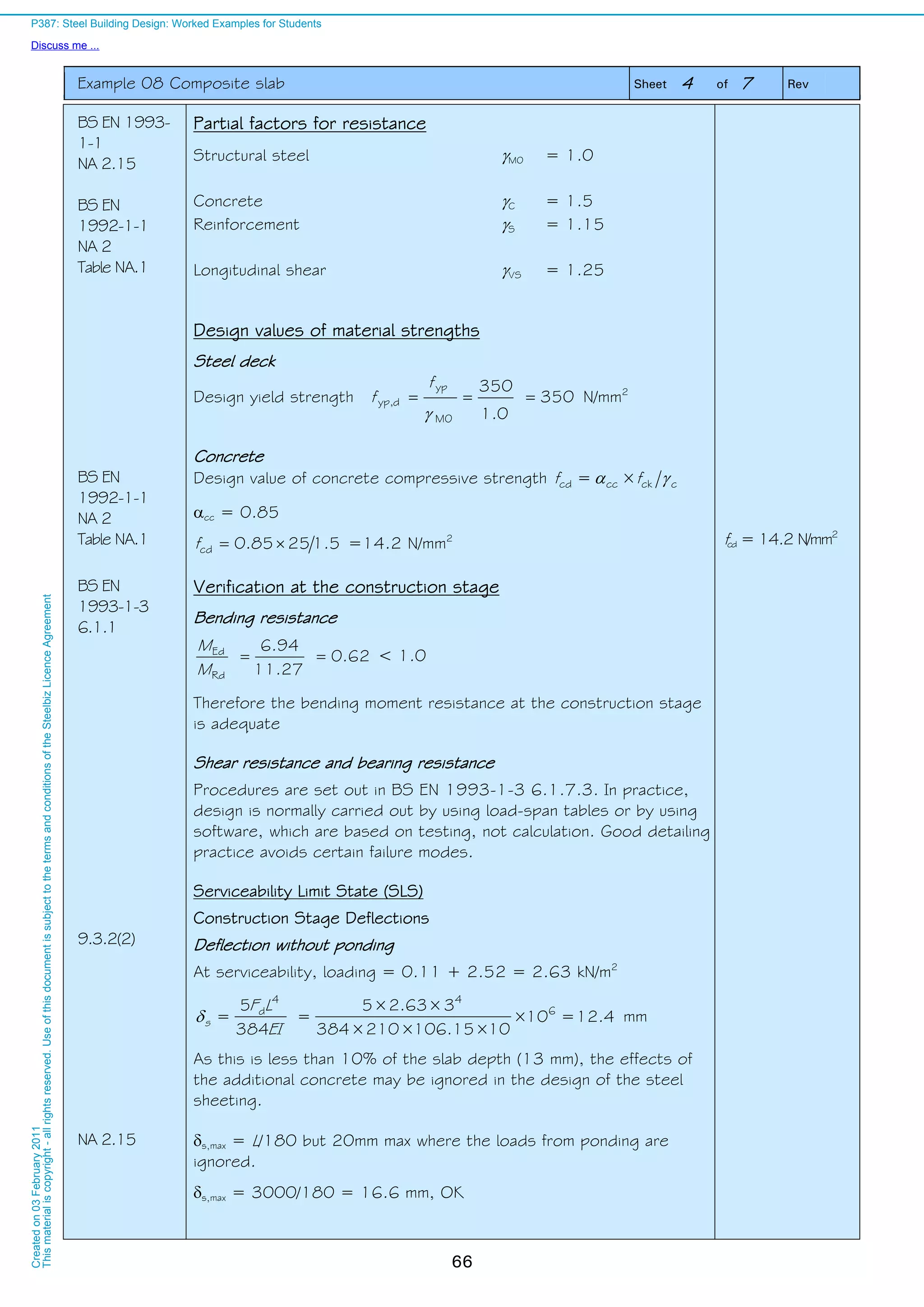
Floor slab and material properties
Total depth of slab h = 130 mm
Corus profiled steel sheeting CF60
Thickness of profile t = 1.0 mm
Depth of profile hp = 60 mm
Span L = 3 m
Effective cross-sectional area of the profile Ape = 1424 mm2
/m
Second moment of area of the profile Ip = 106.15 cm4
/m
Yield strength of the profiled deck fyp = 350 N/mm2
from manufacturer’s data:
Design value of bending resistance (sagging)
MRd = 11.27 KNm/m
Height of neutral axis above soffit: = 30.5 mm
BS EN
1992-1-1
Table 3.1
BS EN
1991-1-1
Table A.1
Concrete
Normal concrete strength class C25/30
Density (normal weight, reinforced) 26 kN/m³ (wet)
25 kN/m³ (dry)
[These density values may vary for a specific project depending on the
amount of steel reinforcement.]
Cylinder strength fck = 25 N/mm2
Modulus of elasticity Ecm = 31 kN/mm2
Actions
Concrete weight
Self weight of the concrete slab (volume from decking manufacturer’s
data)
0.097 × 26 × 10-6
= 2.52 kN/m2
(wet)
0.097 × 25 × 10-6
= 2.43 kN/m2
(dry)
Permanent Actions
Construction stage kN/m2
Steel deck 0.11
Total 0.11
Composite stage kN/m2
Concrete slab 2.43
Steel deck 0.11
Ceiling and services 0.15
Total 2.69
Construction stage:
gk = 0.11 kN/m2
Composite stage:
gk = 2.69 kN/m2
Variable actions
At the construction stage, the loading considered is a 0.75 kN/m²
load across the entire slab, with an additional 0.75 kN/m² load
across a 3 m span, which can be positioned anywhere on the slab
span. In this case the span is 3 m, and so the construction loading
across the whole span is 1.50 kN/m²
P 3 8 7 : S t e e l B u i l d i n g D e s i g n : W o r k e d E x a m p l e s f o r S t u d e n t s
D i s c u s s m e . . .
Createdon03February2011
Thismaterialiscopyright-allrightsreserved.Useofthisdocumentissubjecttoth](https://image.slidesharecdn.com/steelbuildingdesignworkedexample-161119070745/75/Steel-building-design-worked-example-70-2048.jpg)


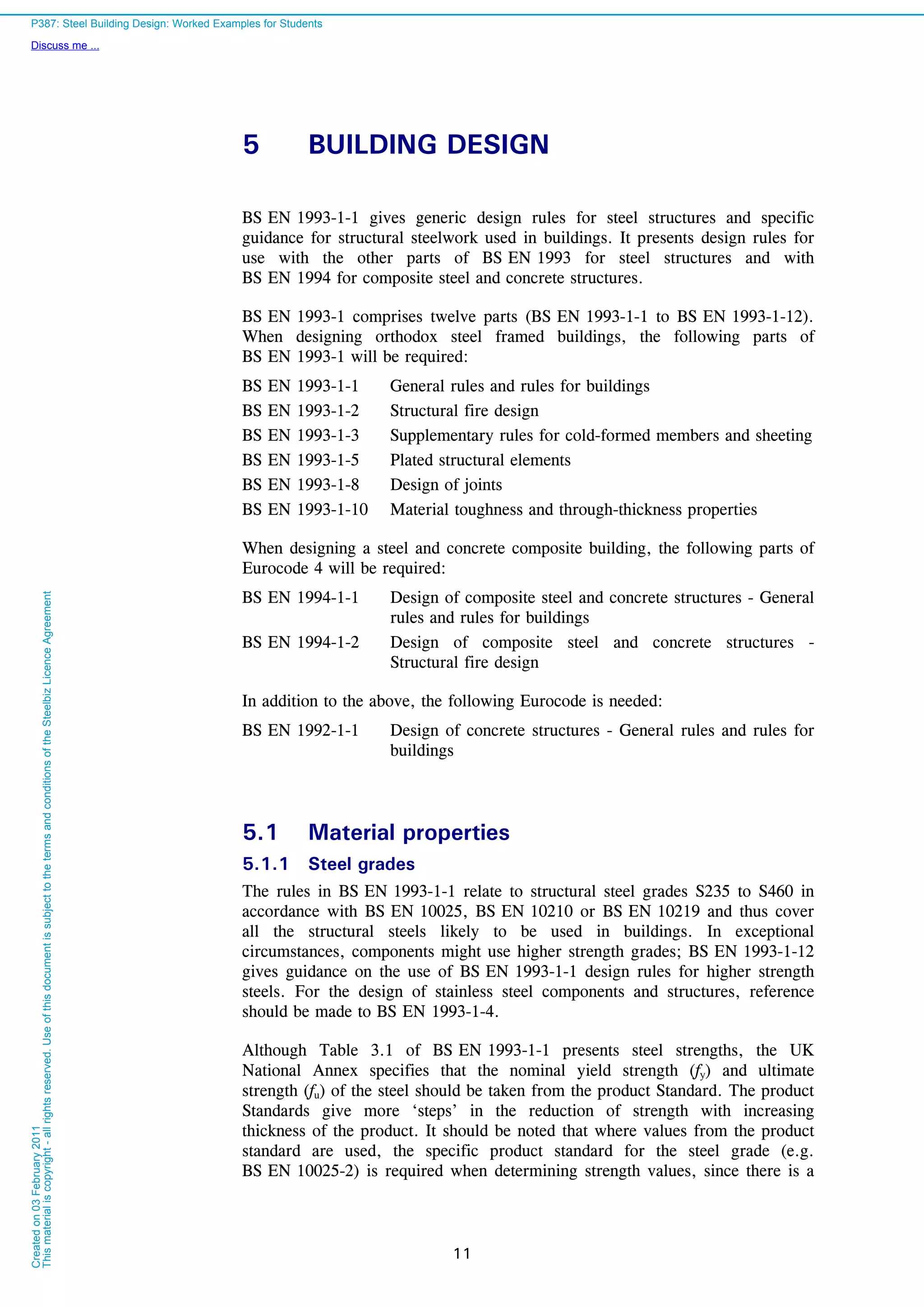
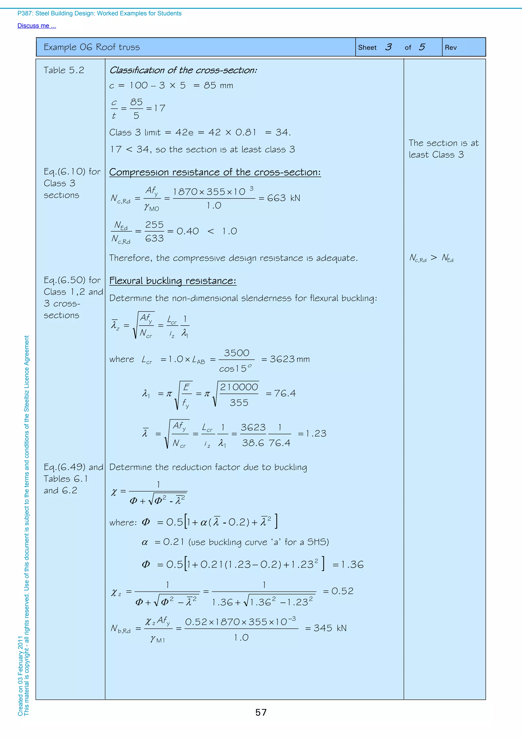
![Example 12 Frame stability Sheet 2 of 4 Rev
94
BS EN 1990
NA 2.2.2
Table
NA A1.1
0 factors
For imposed floor loads (office areas) 0 = 0.7
For snow loads on roofs (H1000m a.s.l) 0 = 0.5
Design value of wind load, as the leading action
Total wind load on windward face of building
= 1.5 925 =1388 kN
Total wind load resisted by braced bay
= 0.5 1388 = 694 kN
Distribution : At roof level = 694 / 8 = 86.8 kN
At floor levels = 694 / 4 = 173.5 kN
Wind loading on
braced bay
5.3.2(3)
Design value of the vertical loads, in combination with wind as
the leading action
Roof loading on one braced frame
= 14 6 [0.925 ×1.35 × 0.9 + 1.5 × 0.5 × 0.6]
= 132.2 kN
Total roof loading
= 8 132.2 = 1058 kN
Equivalent horizontal force (acting as a point load) at roof level in
end frame
= 0.5 0.5% 1058 = 2.7 kN
gk = 0.9 kN/m2
qk = 0.6 kN/m2
(see arrangement
and actions)
Equivalent horizontal
force at roof level
= 2.7 kN
5.3.2(3)
Floor loading on one braced frame
= 14 6 [0.925 ×1.35 3.7 + 1.5 × 0.7 3.3]
= 679 kN
Total floor loading
= 8 679 = 5433 kN
Equivalent horizontal force (acting as a point load) at each floor level
in end frame
= 0.5 0.5% 5433 = 13.6 kN
gk = 3.7 kN/m2
qk = 3.3 kN/m2
(see arrangement
and actions)
Equivalent horizontal
force at each floor
level
= 13.6 kN
Note that in accordance with 5.3.2(3) the equivalent imperfection
forces may be modified (reduced) by h and m. It is conservative to
ignore these reduction factors. Whereas h and m reduce the
magnitude of the forces transferred to the stability system (in this
example, the bracing in the end bays), the effect of h and m on the
value of cr is modest. In this example, h and m have been set to
1.0.
P387: Steel Building Design: Worked Examples for Students
Discuss me ...
Createdon03February2011
Thismaterialiscopyright-allrightsreserved.UseofthisdocumentissubjecttothetermsandconditionsoftheSteelbizLicenceAgreement](https://image.slidesharecdn.com/steelbuildingdesignworkedexample-161119070745/75/Steel-building-design-worked-example-100-2048.jpg)


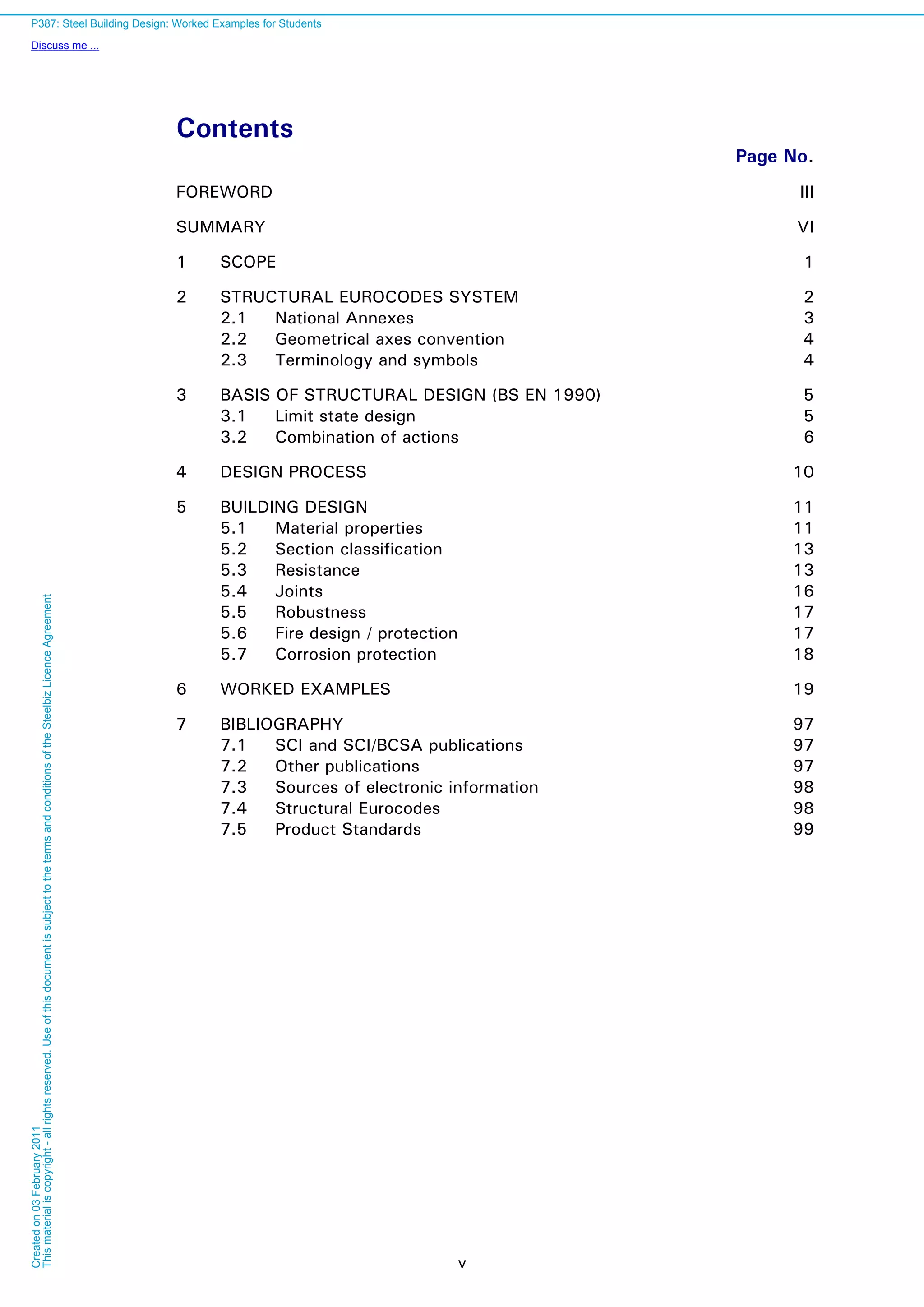
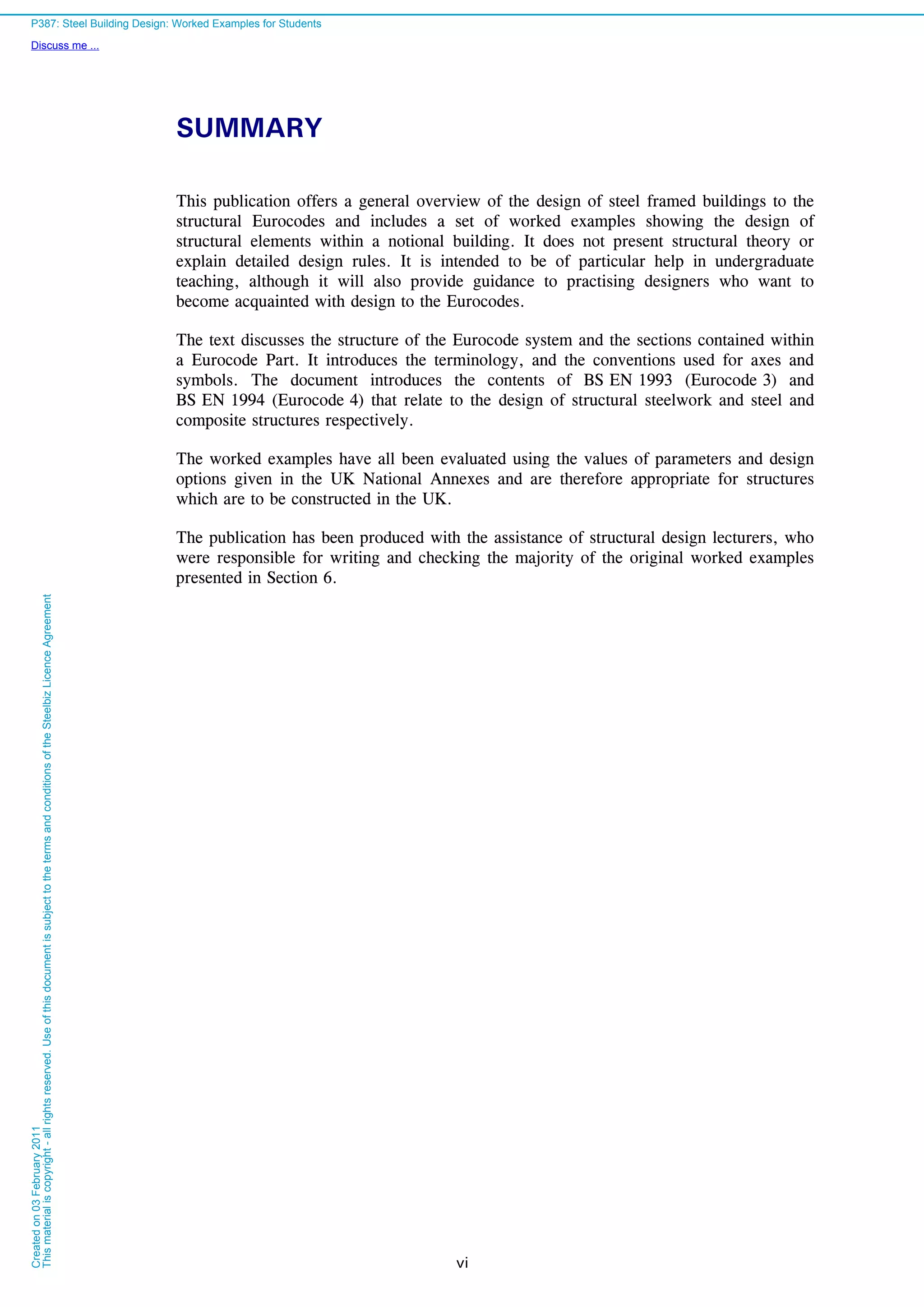
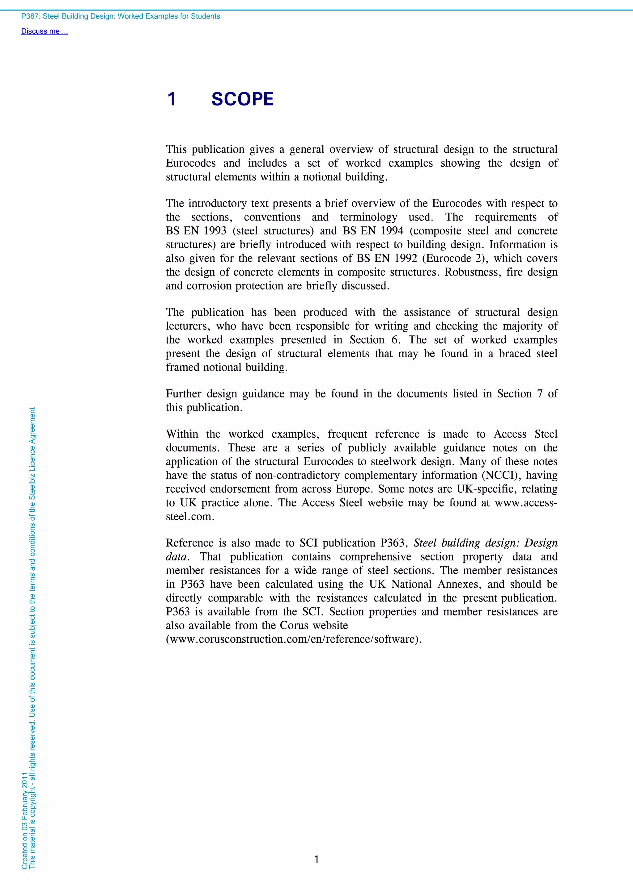
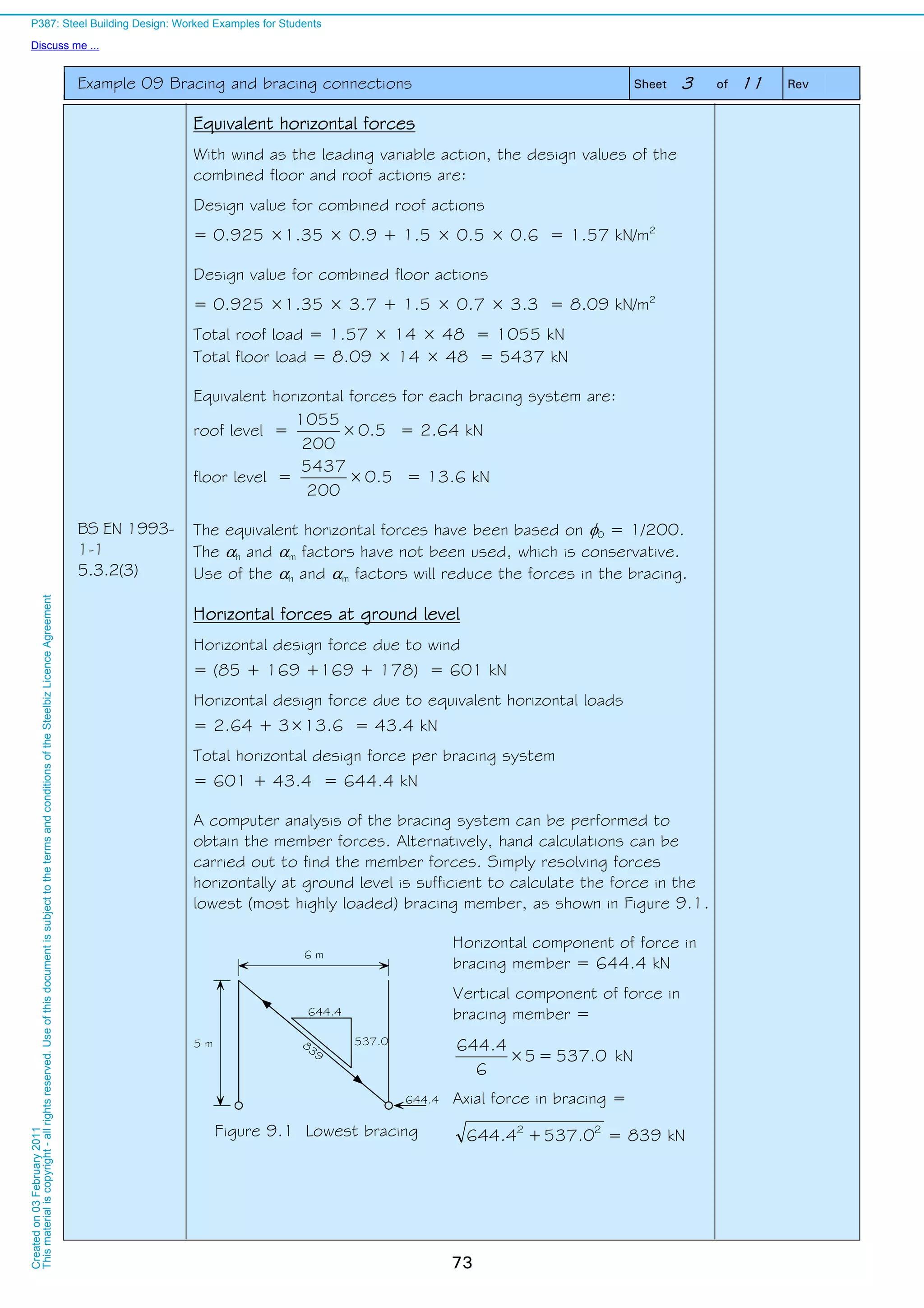
This publication provides worked examples for the design of structural elements in a notional steel framed building according to Eurocode standards. It includes an overview of the Eurocode system and conventions used, and introduces relevant content from Eurocode standards for steel, composite steel and concrete, and concrete structures. The worked examples apply the parameter values and design options specified in the UK National Annexes. They were produced with input from structural design lecturers and are intended to help both students and practicing designers learn Eurocode design methods.