Downloaded 354 times
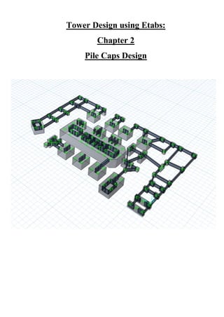
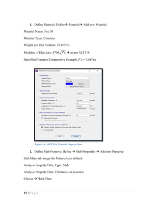
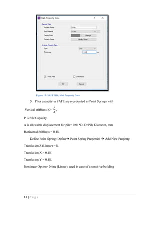
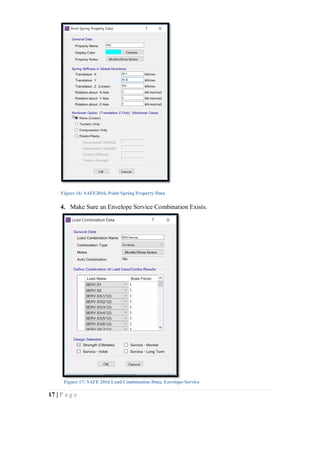
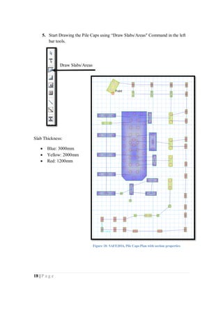

Chapter 2 of 'Tower Design Using ETABS' focuses on pile and pile cap design, explaining the use of piles to transfer loads from structural elements to the foundation. It covers definitions, usage conditions, calculation methods for pile capacity, designing pile caps, and the application of software tools such as AutoCAD, ETABS, and SAFE for structural analysis and design. The document provides comprehensive instructions on determining the necessary number of piles, checking loads, and ensuring appropriate foundation safety.