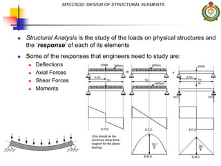
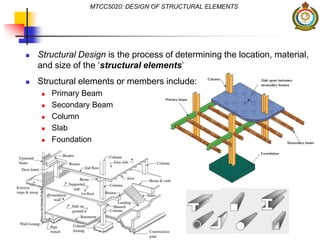
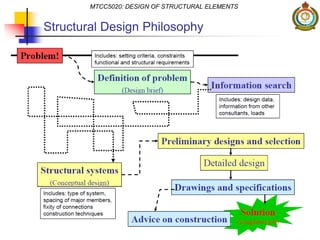
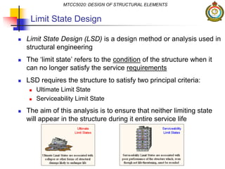
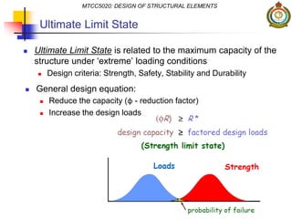
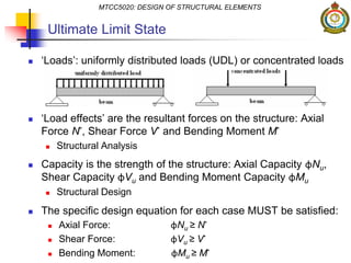
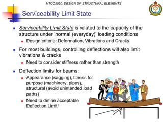
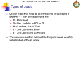
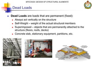
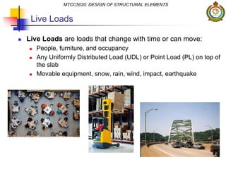
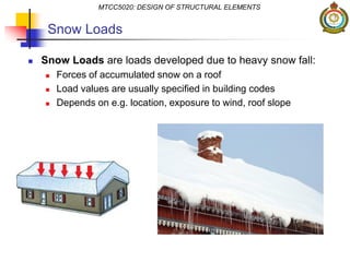
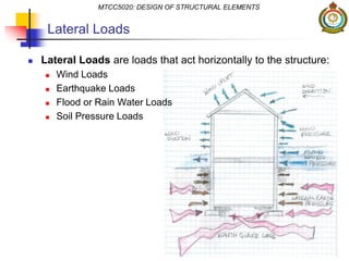
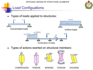
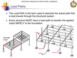
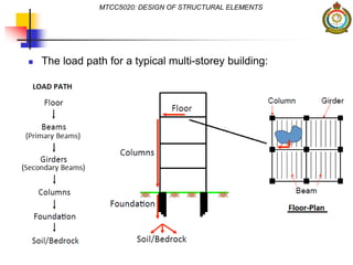
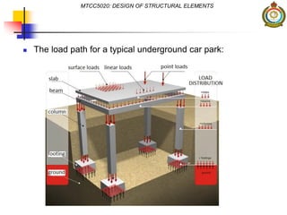
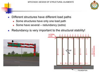
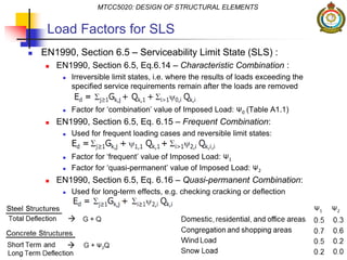
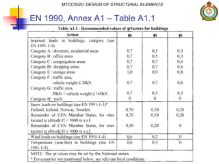
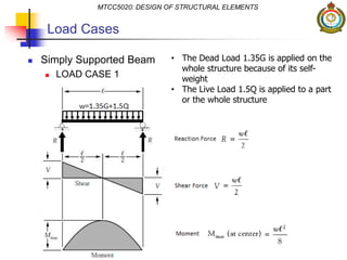
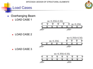
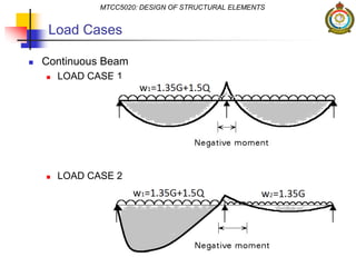
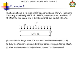
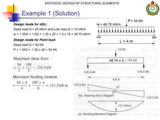
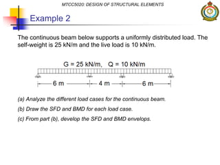
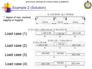
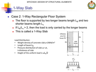
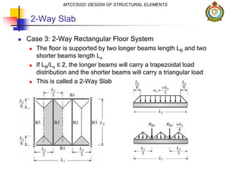
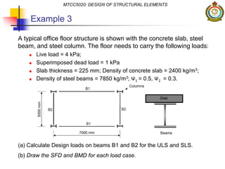
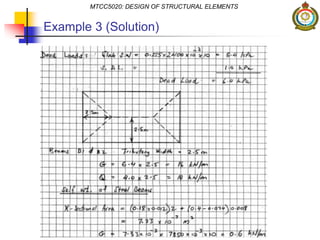
Lecture 1
Design Loads
Dr. Morsaleen Chowdhury
Civil Engineering & Quantity Surveying
Military Technological College
MTCC5020: DESIGN OF STRUCTURAL ELEMENTS
Lecture Outline
 Introduction
 Design philosophy, limit state design, design codes.
 Types of Loads
 Dead, live, snow, lateral, load configurations.
 Load Paths
 Load Factors of Safety
 Factors for SLS and ULS, load cases.
 Example 1, Example 2
 Tributary Area
 Square floors, 1-way and 2-way slabs.
 Example 3
MTCC5020: DESIGN OF STRUCTURAL ELEMENTS
Introduction to
Structural Engineering
 Structural Engineering is the…
the science and art of designing and constructing buildings,
bridges, roads, airports, and many other infrastructures,
with economy and elegance, so that they safely resist the
forces to which they are subjected to…
 Structural Engineers are primarily involved in two major fields:
 Structural Analysis
 Structural Design
MTCC5020: DESIGN OF STRUCTURAL ELEMENTS
 Structural Analysis is the study of the loads on physical structures and
the ‘response’ of each of its elements
 Some of the responses that engineers need to study are:
 Deflections
 Axial Forces
 Shear Forces
 Moments
MTCC5020: DESIGN OF STRUCTURAL ELEMENTS
 Structural Design is the process of determining the location, material,
and size of the ‘structural elements’
 Structural elements or members include:
 Primary Beam
 Secondary Beam
 Column
 Slab
 Foundation
MTCC5020: DESIGN OF STRUCTURAL ELEMENTS
Structural Design Philosophy
MTCC5020: DESIGN OF STRUCTURAL ELEMENTS
Limit State Design
 Limit State Design (LSD) is a design method or analysis used in
structural engineering
 The ‘limit state’ refers to the condition of the structure when it
can no longer satisfy the service requirements
 LSD requires the structure to satisfy two principal criteria:
 Ultimate Limit State
 Serviceability Limit State
 The aim of this analysis is to ensure that neither limiting state
will appear in the structure during it entire service life
MTCC5020: DESIGN OF STRUCTURAL ELEMENTS
Ultimate Limit State
 Ultimate Limit State is related to the maximum capacity of the
structure under ‘extreme’ loading conditions
 Design criteria: Strength, Safety, Stability and Durability
 General design equation:
 Reduce the capacity (φ - reduction factor)
 Increase the design loads
MTCC5020: DESIGN OF STRUCTURAL ELEMENTS
Ultimate Limit State
 ‘Loads’: uniformly distributed loads (UDL) or concentrated loads
 ‘Load effects’ are the resultant forces on the structure: Axial
Force N*, Shear Force V* and Bending Moment M*
 Structural Analysis
 Capacity is the strength of the structure: Axial Capacity φNu,
Shear Capacity φVu and Bending Moment Capacity φMu
 Structural Design
 The specific design equation for each case MUST be satisfied:
 Axial Force: φNu ≥ N*
 Shear Force: φVu ≥ V*
 Bending Moment: φMu ≥ M*
MTCC5020: DESIGN OF STRUCTURAL ELEMENTS
Serviceability Limit State
 Serviceability Limit State is related to the capacity of the
structure under ‘normal (everyday)’ loading conditions
 Design criteria: Deformation, Vibrations and Cracks
 For most buildings, controlling deflections will also limit
vibrations & cracks
 Need to consider stiffness rather than strength
 Deflection limits for beams:
 Appearance (sagging), fitness for
purpose (machinery, pipes),
structural (avoid unintended load
paths)
 Need to define acceptable
Deflection Limit!
MTCC5020: DESIGN OF STRUCTURAL ELEMENTS
Structural Design Codes
 A guideline is needed to design a structure in satisfaction of
Ultimate & Serviceability Limit States, e.g.:
 Design loads & load factors
 Capacity (strength) & reduction factors
 Deflection limits
 Structural Design Codes provide a basis for designing all types
of structures, e.g. international standards:
 Australia – e.g. AS3600, AS4100
 America – e.g. AISC 360-10, ACI 318
 Europe – Eurocodes
 This Module will focus on the Eurocodes for the design of
structural elements
MTCC5020: DESIGN OF STRUCTURAL ELEMENTS
Eurocodes
There are 10 specific Eurocodes:
MTCC5020: DESIGN OF STRUCTURAL ELEMENTS
Eurocodes
 Each Eurocode may consist of several parts, e.g. EN1991
Eurocode 1: Actions on Structures
 EN1991-1-1: Densities, Self-Weight, Imposed Loads for Buildings
 EN1991-1-2: Actions on Structures Exposed to Fire
 EN1991-1-3: General Actions – Snow Loads
 This Module will apply the following Eurocodes:
 EN1990: Basis of Structural Design
 EN1991-1-1: Densities, Self-Weight, Imposed Loads for Buildings
 EN1992-1-1: General Rules and Rules for Buildings (Concrete)
 EN1993-1-1: General Rules and Rules for Buildings (Steel)
 MUST have a copy of each of these Eurocodes!
MTCC5020: DESIGN OF STRUCTURAL ELEMENTS
Types of Loads
Types of Loads
 Design loads that need to be considered in Eurocode 1
EN1991-1-1 can be categorized into:
 G – Dead Load
 Q – Live Load due to UDL or PL
 W – Live Load due to Wind
 S – Live Load due to Snow
 E – Live Load due to Earthquake
 The structure must be adequately designed so as to safely
withstand all of these loads
MTCC5020: DESIGN OF STRUCTURAL ELEMENTS
 Dead Loads are loads that are permanent (fixed):
 Always act vertically on the structure
 Self-Weight – weight of the actual structural members
 Superimposed – objects that are permanently attached to the
structure (floors, roofs, decks)
 Concrete slab, stationary equipment, partitions, etc.
MTCC5020: DESIGN OF STRUCTURAL ELEMENTS
Dead Loads
 Live Loads are loads that change with time or can move:
 People, furniture, and occupancy
 Any Uniformly Distributed Load (UDL) or Point Load (PL) on top of
the slab
 Movable equipment, snow, rain, wind, impact, earthquake
MTCC5020: DESIGN OF STRUCTURAL ELEMENTS
Live Loads
 Snow Loads are loads developed due to heavy snow fall:
 Forces of accumulated snow on a roof
 Load values are usually specified in building codes
 Depends on e.g. location, exposure to wind, roof slope
MTCC5020: DESIGN OF STRUCTURAL ELEMENTS
Snow Loads
 Lateral Loads are loads that act horizontally to the structure:
 Wind Loads
 Earthquake Loads
 Flood or Rain Water Loads
 Soil Pressure Loads
MTCC5020: DESIGN OF STRUCTURAL ELEMENTS
Lateral Loads
 Types of loads applied to structures:
 Types of actions exerted on structural members:
MTCC5020: DESIGN OF STRUCTURAL ELEMENTS
Load Configuations
MTCC5020: DESIGN OF STRUCTURAL ELEMENTS
Load Paths
Load Paths
 The Load Path is the term used to describe the actual path that
a load travels through the structural system
 Every structure MUST have a load path to transfer the applied
loads SAFELY to the foundation
MTCC5020: DESIGN OF STRUCTURAL ELEMENTS
 The load path for a typical multi-storey building:
MTCC5020: DESIGN OF STRUCTURAL ELEMENTS
 The load path for a typical underground car park:
MTCC5020: DESIGN OF STRUCTURAL ELEMENTS
 Different structures have different load paths
 Some structures have only one load path
 Some have several – redundancy (extra)
 Redundancy is very important to the structural stability!
MTCC5020: DESIGN OF STRUCTURAL ELEMENTS
Design Load Factors
Load Factors for ULS
 EN1990, Section 6.4 – Ultimate Limit State (ULS) examples of load
combination using Eq. 6.10:
1. Dead Load 1.35G
2. Dead Load + Live Load 1.35G +1.5Q
3. Dead Load + Live Load + Wind Load 1.35G + 1.5Q + 1.5×0.6×W
4. Dead Load + Live Load + Snow Load 1.35G + 1.5Q + 1.5×0.5×S
 From EN1990, Annex A1 – Table A1.1
 Domestic, residential, office, congregation, shopping areas Ψ0 = 0.7
 Storage areas Ψ0 = 1.0, Wind Load Ψ0 = 0.6, Snow Load Ψ0 = 0.5
MTCC5020: DESIGN OF STRUCTURAL ELEMENTS
Load Factors for SLS
 EN1990, Section 6.5 – Serviceability Limit State (SLS) :
 EN1990, Section 6.5, Eq.6.14 – Characteristic Combination :
 Irreversible limit states, i.e. where the results of loads exceeding the
specified service requirements remain after the loads are removed
 Factor for ‘combination’ value of Imposed Load: Ψ0 (Table A1.1)
 EN1990, Section 6.5, Eq. 6.15 – Frequent Combination:
 Used for frequent loading cases and reversible limit states:
 Factor for ‘frequent’ value of Imposed Load: Ψ1
 Factor for ‘quasi-permanent’ value of Imposed Load: Ψ2
 EN1990, Section 6.5, Eq. 6.16 – Quasi-permanent Combination:
 Used for long-term effects, e.g. checking cracking or deflection
MTCC5020: DESIGN OF STRUCTURAL ELEMENTS
EN 1990, Annex A1 – Table A1.1
MTCC5020: DESIGN OF STRUCTURAL ELEMENTS
Load Cases
 Simply Supported Beam
 LOAD CASE 1
MTCC5020: DESIGN OF STRUCTURAL ELEMENTS
• The Dead Load 1.35G is applied on the
whole structure because of its self-
weight
• The Live Load 1.5Q is applied to a part
or the whole structure
Load Cases
 Overhanging Beam
 LOAD CASE 1
 LOAD CASE 2
 LOAD CASE 3
MTCC5020: DESIGN OF STRUCTURAL ELEMENTS
Load Cases
 Continuous Beam
 LOAD CASE 1
 LOAD CASE 2
MTCC5020: DESIGN OF STRUCTURAL ELEMENTS
Example 1
The figure shows a 4m long simply supported beam shown. The beam
is to carry a self-weight UDL of 25 kN/m, a concentrated dead load of
40 kN at the mid-span, and a distributed UDL live load of 10 kN/m.
(a) Calculate the design loads of w and P for the ultimate limit state (ULS).
(b) Draw the shear force diagram (SFD) and bending moment diagram (BMD).
(c) What are the maximum design shear force and bending moment?
MTCC5020: DESIGN OF STRUCTURAL ELEMENTS
Example 1 (Solution)
MTCC5020: DESIGN OF STRUCTURAL ELEMENTS
Example 2
The continuous beam below supports a uniformly distributed load. The
self-weight is 25 kN/m and the live load is 10 kN/m.
(a) Analyze the different load cases for the continuous beam.
(b) Draw the SFD and BMD for each load case.
(c) From part (b), develop the SFD and BMD envelops.
MTCC5020: DESIGN OF STRUCTURAL ELEMENTS
Example 2 (Solution)
MTCC5020: DESIGN OF STRUCTURAL ELEMENTS
* Region of max. moment,
sagging or hogging
Example 2 (Solution)
MTCC5020: DESIGN OF STRUCTURAL ELEMENTS
SFD envelope
Example 2 (Solution)
MTCC5020: DESIGN OF STRUCTURAL ELEMENTS
BMD envelope
MTCC5020: DESIGN OF STRUCTURAL ELEMENTS
Tributary Area
Tributary Area
 The distribution of the floor loads on the beams is based on the
geometric configuration of the beams forming the grid
MTCC5020: DESIGN OF STRUCTURAL ELEMENTS
Load distribution for a typical office floor
Square Floor
 Case 1: Square Floor System
 All the edge beams will support the same triangular load
 The area of the slab portion that is supported by a particular beam
is called the Tributary Area
MTCC5020: DESIGN OF STRUCTURAL ELEMENTS
Load Distribution:
• Weight density of concrete slab γ=24kN/m3
• Length of beam L
• Pressure distribution of slab ω= γt,
t=thickness of slab
• Height of the triangular load is ωL/2
Concrete Slab
1-Way Slab
 Case 2: 1-Way Rectangular Floor System
 The floor is supported by two longer beams length LB and two
shorter beams length Ls
 If LB/Ls > 2, then the load is only carried by the longer beams
 This is called a 1-Way Slab
MTCC5020: DESIGN OF STRUCTURAL ELEMENTS
Load Distribution:
• Weight density of concrete slab γ=24kN/m3
• Length of beam LB
• Pressure distribution of slab ω= γt,
t=thickness of slab
• Height of the uniform load is ωLs/2
2-Way Slab
 Case 3: 2-Way Rectangular Floor System
 The floor is supported by two longer beams length LB and two
shorter beams length Ls
 If LB/Ls ≤ 2, the longer beams will carry a trapezoidal load
distribution and the shorter beams will carry a triangular load
 This is called a 2-Way Slab
MTCC5020: DESIGN OF STRUCTURAL ELEMENTS
Example 3
A typical office floor structure is shown with the concrete slab, steel
beam, and steel column. The floor needs to carry the following loads:
 Live load = 4 kPa;
 Superimposed dead load = 1 kPa
 Slab thickness = 225 mm; Density of concrete slab = 2400 kg/m3;
 Density of steel beams = 7850 kg/m3; Ψ1 = 0.5, Ψ2 = 0.3.
(a) Calculate Design loads on beams B1 and B2 for the ULS and SLS.
(b) Draw the SFD and BMD for each load case.
MTCC5020: DESIGN OF STRUCTURAL ELEMENTS
Example 3 (Solution)
MTCC5020: DESIGN OF STRUCTURAL ELEMENTS
Example 3 (Solution)
MTCC5020: DESIGN OF STRUCTURAL ELEMENTS
End Lecture

Lecture 1 design loads

  • 1.
    Lecture 1 Design Loads Dr.Morsaleen Chowdhury Civil Engineering & Quantity Surveying Military Technological College MTCC5020: DESIGN OF STRUCTURAL ELEMENTS
  • 2.
    Lecture Outline  Introduction Design philosophy, limit state design, design codes.  Types of Loads  Dead, live, snow, lateral, load configurations.  Load Paths  Load Factors of Safety  Factors for SLS and ULS, load cases.  Example 1, Example 2  Tributary Area  Square floors, 1-way and 2-way slabs.  Example 3 MTCC5020: DESIGN OF STRUCTURAL ELEMENTS
  • 3.
    MTCC5020: DESIGN OFSTRUCTURAL ELEMENTS Introduction to Structural Engineering
  • 4.
    Structural Engineering  StructuralEngineering is the… the science and art of designing and constructing buildings, bridges, roads, airports, and many other infrastructures, with economy and elegance, so that they safely resist the forces to which they are subjected to…  Structural Engineers are primarily involved in two major fields:  Structural Analysis  Structural Design MTCC5020: DESIGN OF STRUCTURAL ELEMENTS
  • 5.
     Structural Analysisis the study of the loads on physical structures and the ‘response’ of each of its elements  Some of the responses that engineers need to study are:  Deflections  Axial Forces  Shear Forces  Moments MTCC5020: DESIGN OF STRUCTURAL ELEMENTS
  • 6.
     Structural Designis the process of determining the location, material, and size of the ‘structural elements’  Structural elements or members include:  Primary Beam  Secondary Beam  Column  Slab  Foundation MTCC5020: DESIGN OF STRUCTURAL ELEMENTS
  • 7.
    Structural Design Philosophy MTCC5020:DESIGN OF STRUCTURAL ELEMENTS
  • 8.
    Limit State Design Limit State Design (LSD) is a design method or analysis used in structural engineering  The ‘limit state’ refers to the condition of the structure when it can no longer satisfy the service requirements  LSD requires the structure to satisfy two principal criteria:  Ultimate Limit State  Serviceability Limit State  The aim of this analysis is to ensure that neither limiting state will appear in the structure during it entire service life MTCC5020: DESIGN OF STRUCTURAL ELEMENTS
  • 9.
    Ultimate Limit State Ultimate Limit State is related to the maximum capacity of the structure under ‘extreme’ loading conditions  Design criteria: Strength, Safety, Stability and Durability  General design equation:  Reduce the capacity (φ - reduction factor)  Increase the design loads MTCC5020: DESIGN OF STRUCTURAL ELEMENTS
  • 10.
    Ultimate Limit State ‘Loads’: uniformly distributed loads (UDL) or concentrated loads  ‘Load effects’ are the resultant forces on the structure: Axial Force N*, Shear Force V* and Bending Moment M*  Structural Analysis  Capacity is the strength of the structure: Axial Capacity φNu, Shear Capacity φVu and Bending Moment Capacity φMu  Structural Design  The specific design equation for each case MUST be satisfied:  Axial Force: φNu ≥ N*  Shear Force: φVu ≥ V*  Bending Moment: φMu ≥ M* MTCC5020: DESIGN OF STRUCTURAL ELEMENTS
  • 11.
    Serviceability Limit State Serviceability Limit State is related to the capacity of the structure under ‘normal (everyday)’ loading conditions  Design criteria: Deformation, Vibrations and Cracks  For most buildings, controlling deflections will also limit vibrations & cracks  Need to consider stiffness rather than strength  Deflection limits for beams:  Appearance (sagging), fitness for purpose (machinery, pipes), structural (avoid unintended load paths)  Need to define acceptable Deflection Limit! MTCC5020: DESIGN OF STRUCTURAL ELEMENTS
  • 12.
    Structural Design Codes A guideline is needed to design a structure in satisfaction of Ultimate & Serviceability Limit States, e.g.:  Design loads & load factors  Capacity (strength) & reduction factors  Deflection limits  Structural Design Codes provide a basis for designing all types of structures, e.g. international standards:  Australia – e.g. AS3600, AS4100  America – e.g. AISC 360-10, ACI 318  Europe – Eurocodes  This Module will focus on the Eurocodes for the design of structural elements MTCC5020: DESIGN OF STRUCTURAL ELEMENTS
  • 13.
    Eurocodes There are 10specific Eurocodes: MTCC5020: DESIGN OF STRUCTURAL ELEMENTS
  • 14.
    Eurocodes  Each Eurocodemay consist of several parts, e.g. EN1991 Eurocode 1: Actions on Structures  EN1991-1-1: Densities, Self-Weight, Imposed Loads for Buildings  EN1991-1-2: Actions on Structures Exposed to Fire  EN1991-1-3: General Actions – Snow Loads  This Module will apply the following Eurocodes:  EN1990: Basis of Structural Design  EN1991-1-1: Densities, Self-Weight, Imposed Loads for Buildings  EN1992-1-1: General Rules and Rules for Buildings (Concrete)  EN1993-1-1: General Rules and Rules for Buildings (Steel)  MUST have a copy of each of these Eurocodes! MTCC5020: DESIGN OF STRUCTURAL ELEMENTS
  • 15.
    MTCC5020: DESIGN OFSTRUCTURAL ELEMENTS Types of Loads
  • 16.
    Types of Loads Design loads that need to be considered in Eurocode 1 EN1991-1-1 can be categorized into:  G – Dead Load  Q – Live Load due to UDL or PL  W – Live Load due to Wind  S – Live Load due to Snow  E – Live Load due to Earthquake  The structure must be adequately designed so as to safely withstand all of these loads MTCC5020: DESIGN OF STRUCTURAL ELEMENTS
  • 17.
     Dead Loadsare loads that are permanent (fixed):  Always act vertically on the structure  Self-Weight – weight of the actual structural members  Superimposed – objects that are permanently attached to the structure (floors, roofs, decks)  Concrete slab, stationary equipment, partitions, etc. MTCC5020: DESIGN OF STRUCTURAL ELEMENTS Dead Loads
  • 18.
     Live Loadsare loads that change with time or can move:  People, furniture, and occupancy  Any Uniformly Distributed Load (UDL) or Point Load (PL) on top of the slab  Movable equipment, snow, rain, wind, impact, earthquake MTCC5020: DESIGN OF STRUCTURAL ELEMENTS Live Loads
  • 19.
     Snow Loadsare loads developed due to heavy snow fall:  Forces of accumulated snow on a roof  Load values are usually specified in building codes  Depends on e.g. location, exposure to wind, roof slope MTCC5020: DESIGN OF STRUCTURAL ELEMENTS Snow Loads
  • 20.
     Lateral Loadsare loads that act horizontally to the structure:  Wind Loads  Earthquake Loads  Flood or Rain Water Loads  Soil Pressure Loads MTCC5020: DESIGN OF STRUCTURAL ELEMENTS Lateral Loads
  • 21.
     Types ofloads applied to structures:  Types of actions exerted on structural members: MTCC5020: DESIGN OF STRUCTURAL ELEMENTS Load Configuations
  • 22.
    MTCC5020: DESIGN OFSTRUCTURAL ELEMENTS Load Paths
  • 23.
    Load Paths  TheLoad Path is the term used to describe the actual path that a load travels through the structural system  Every structure MUST have a load path to transfer the applied loads SAFELY to the foundation MTCC5020: DESIGN OF STRUCTURAL ELEMENTS
  • 24.
     The loadpath for a typical multi-storey building: MTCC5020: DESIGN OF STRUCTURAL ELEMENTS
  • 25.
     The loadpath for a typical underground car park: MTCC5020: DESIGN OF STRUCTURAL ELEMENTS
  • 26.
     Different structureshave different load paths  Some structures have only one load path  Some have several – redundancy (extra)  Redundancy is very important to the structural stability! MTCC5020: DESIGN OF STRUCTURAL ELEMENTS
  • 27.
    MTCC5020: DESIGN OFSTRUCTURAL ELEMENTS Design Load Factors
  • 28.
    Load Factors forULS  EN1990, Section 6.4 – Ultimate Limit State (ULS) examples of load combination using Eq. 6.10: 1. Dead Load 1.35G 2. Dead Load + Live Load 1.35G +1.5Q 3. Dead Load + Live Load + Wind Load 1.35G + 1.5Q + 1.5×0.6×W 4. Dead Load + Live Load + Snow Load 1.35G + 1.5Q + 1.5×0.5×S  From EN1990, Annex A1 – Table A1.1  Domestic, residential, office, congregation, shopping areas Ψ0 = 0.7  Storage areas Ψ0 = 1.0, Wind Load Ψ0 = 0.6, Snow Load Ψ0 = 0.5 MTCC5020: DESIGN OF STRUCTURAL ELEMENTS
  • 29.
    Load Factors forSLS  EN1990, Section 6.5 – Serviceability Limit State (SLS) :  EN1990, Section 6.5, Eq.6.14 – Characteristic Combination :  Irreversible limit states, i.e. where the results of loads exceeding the specified service requirements remain after the loads are removed  Factor for ‘combination’ value of Imposed Load: Ψ0 (Table A1.1)  EN1990, Section 6.5, Eq. 6.15 – Frequent Combination:  Used for frequent loading cases and reversible limit states:  Factor for ‘frequent’ value of Imposed Load: Ψ1  Factor for ‘quasi-permanent’ value of Imposed Load: Ψ2  EN1990, Section 6.5, Eq. 6.16 – Quasi-permanent Combination:  Used for long-term effects, e.g. checking cracking or deflection MTCC5020: DESIGN OF STRUCTURAL ELEMENTS
  • 30.
    EN 1990, AnnexA1 – Table A1.1 MTCC5020: DESIGN OF STRUCTURAL ELEMENTS
  • 31.
    Load Cases  SimplySupported Beam  LOAD CASE 1 MTCC5020: DESIGN OF STRUCTURAL ELEMENTS • The Dead Load 1.35G is applied on the whole structure because of its self- weight • The Live Load 1.5Q is applied to a part or the whole structure
  • 32.
    Load Cases  OverhangingBeam  LOAD CASE 1  LOAD CASE 2  LOAD CASE 3 MTCC5020: DESIGN OF STRUCTURAL ELEMENTS
  • 33.
    Load Cases  ContinuousBeam  LOAD CASE 1  LOAD CASE 2 MTCC5020: DESIGN OF STRUCTURAL ELEMENTS
  • 34.
    Example 1 The figureshows a 4m long simply supported beam shown. The beam is to carry a self-weight UDL of 25 kN/m, a concentrated dead load of 40 kN at the mid-span, and a distributed UDL live load of 10 kN/m. (a) Calculate the design loads of w and P for the ultimate limit state (ULS). (b) Draw the shear force diagram (SFD) and bending moment diagram (BMD). (c) What are the maximum design shear force and bending moment? MTCC5020: DESIGN OF STRUCTURAL ELEMENTS
  • 35.
    Example 1 (Solution) MTCC5020:DESIGN OF STRUCTURAL ELEMENTS
  • 36.
    Example 2 The continuousbeam below supports a uniformly distributed load. The self-weight is 25 kN/m and the live load is 10 kN/m. (a) Analyze the different load cases for the continuous beam. (b) Draw the SFD and BMD for each load case. (c) From part (b), develop the SFD and BMD envelops. MTCC5020: DESIGN OF STRUCTURAL ELEMENTS
  • 37.
    Example 2 (Solution) MTCC5020:DESIGN OF STRUCTURAL ELEMENTS * Region of max. moment, sagging or hogging
  • 38.
    Example 2 (Solution) MTCC5020:DESIGN OF STRUCTURAL ELEMENTS SFD envelope
  • 39.
    Example 2 (Solution) MTCC5020:DESIGN OF STRUCTURAL ELEMENTS BMD envelope
  • 40.
    MTCC5020: DESIGN OFSTRUCTURAL ELEMENTS Tributary Area
  • 41.
    Tributary Area  Thedistribution of the floor loads on the beams is based on the geometric configuration of the beams forming the grid MTCC5020: DESIGN OF STRUCTURAL ELEMENTS Load distribution for a typical office floor
  • 42.
    Square Floor  Case1: Square Floor System  All the edge beams will support the same triangular load  The area of the slab portion that is supported by a particular beam is called the Tributary Area MTCC5020: DESIGN OF STRUCTURAL ELEMENTS Load Distribution: • Weight density of concrete slab γ=24kN/m3 • Length of beam L • Pressure distribution of slab ω= γt, t=thickness of slab • Height of the triangular load is ωL/2 Concrete Slab
  • 43.
    1-Way Slab  Case2: 1-Way Rectangular Floor System  The floor is supported by two longer beams length LB and two shorter beams length Ls  If LB/Ls > 2, then the load is only carried by the longer beams  This is called a 1-Way Slab MTCC5020: DESIGN OF STRUCTURAL ELEMENTS Load Distribution: • Weight density of concrete slab γ=24kN/m3 • Length of beam LB • Pressure distribution of slab ω= γt, t=thickness of slab • Height of the uniform load is ωLs/2
  • 44.
    2-Way Slab  Case3: 2-Way Rectangular Floor System  The floor is supported by two longer beams length LB and two shorter beams length Ls  If LB/Ls ≤ 2, the longer beams will carry a trapezoidal load distribution and the shorter beams will carry a triangular load  This is called a 2-Way Slab MTCC5020: DESIGN OF STRUCTURAL ELEMENTS
  • 45.
    Example 3 A typicaloffice floor structure is shown with the concrete slab, steel beam, and steel column. The floor needs to carry the following loads:  Live load = 4 kPa;  Superimposed dead load = 1 kPa  Slab thickness = 225 mm; Density of concrete slab = 2400 kg/m3;  Density of steel beams = 7850 kg/m3; Ψ1 = 0.5, Ψ2 = 0.3. (a) Calculate Design loads on beams B1 and B2 for the ULS and SLS. (b) Draw the SFD and BMD for each load case. MTCC5020: DESIGN OF STRUCTURAL ELEMENTS
  • 46.
    Example 3 (Solution) MTCC5020:DESIGN OF STRUCTURAL ELEMENTS
  • 47.
    Example 3 (Solution) MTCC5020:DESIGN OF STRUCTURAL ELEMENTS
  • 48.
    MTCC5020: DESIGN OFSTRUCTURAL ELEMENTS End Lecture