Downloaded 291 times
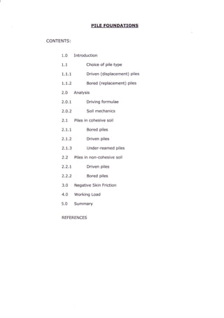


![Piles usually penetrate several different soil types, each providing different shaft
resistances and the total shaft resistance is the summation of the individual
values.
The weight of the pile is usually ignored in the above equations, since it is
approximately equal to the weight of soil removed or displaced.
2.t Piles in cohesive soil (claylsilt ; 0 = O")
Ultimate pile capacity, Q, = Qo + Qs
QU
2.1.1 Bored oiles
Base resistance, Qo (kN):
Where
Shaft resistance, Q.(kN) :
Where
Qb
I
I
= qb Ab
= cu N6 A6
= base bearing capacity = cu Nc
= cross sectional area of pile base (mz)
= undrained shear strength at base of pile
= bearins capac*v factor =
?:9J'fti3ji.il}?]"",1,
=CaAs
= adhesion
= ad,
= adhesion factor
[usually taken as 0.45, but may vary from
1.0 for soft clays to
0.3 for overconsolidated claysl
= average undrained shear strength over length
of pile, L
= diameter of pile
= length of pile in contact with soil stratum
-6-
Pile Foundations v'l .00 Oct2010
Qr
qb
At
Cu
Nc
Qt
C6
Cu
d
L](https://image.slidesharecdn.com/pilefoundation-140711140414-phpapp02/85/Pile-foundation-6-320.jpg)
![Class example 1
A bored pile, 750mm diameter and 12.0m long, is to be installed on a
site where two layers of clay exist;
Upper firm clay; 8.0m thick;
undrained shear strength = 50.0 kN/m'z.
Lower stiff clay; 12.0m thick;
undrained shear strength = 120.0kN/m2.
Determine the working load the pile could support assuming the
following:
i) o = O.7 for firm clay and 0.5 for stiff clay I N. = 9
ii) Factors of safety of 1.5 and 3.0 are applied to the shaft
load and base load respectively
iii) The top 1.0m of the firm clay is ignored due to
clay/concrete shrinkaqe. [921 kN]
Class example 2
For the ground conditions and assumptions described in Example 1,
determine the length of pile required to support a working load of
1200 kN. 114.96m, say 15mI
2.1.2 Under-reamed oiles
Often used in cohesive soils to increase
the base area of the pile, thereby
increasing the base resistance.
For under-reamed piles the adhesion
should be ignored over the:
a) height of the under-ream.
b) main shaft of the pile up to 2 shaft
diameters above the top of the
under-ream and
c) top 1m of the pile (zone of seasonal
shrinkage).
Und et rea.tt
A
lq,
Class example 3
A large under-reamed bored pile is to be installed in stiff clay with
undrained shear strength of 125kN/m2. The main shaft of the pile is
1.5m diameter and the base of the under ream is 4.5m diameter with a
height of 3.0m and the total length of the pile from the ground level to
the base of the under ream is 27m.
Determine the working load of the pile in MN, assuming the following:
a)cr=0.3 i N.=9
b) A factor of safety of 3.0 should be applied to the base load
but full mobilisation of shaft adhesion can be assumed.
t9.498MNl
-7-
Pile Foundations v1 .00 Oct2010](https://image.slidesharecdn.com/pilefoundation-140711140414-phpapp02/85/Pile-foundation-7-320.jpg)


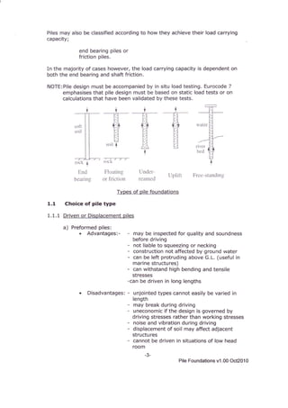
![1.6
Driven pilcs
/
Jacked piles
Bored piles
1.2
-o
! 0.8
k
0..1
o:b :1-s "10
Initial angle of internal lriction @',
Class example 5
A 10.5m long concrete pile, 400mm square, is to be driven into a thick
deposit of medium dense sand, with an SPT'N'value of 25 and a bulk
unit weight of 20.0 kN/m2. The water table lies at 2.5m below ground
level,
Estimate the working load this length of pile will support assuming an
overall factor of safety of 2.5 and the sand has a saturated unit weight
of 20.0kN/m3
[949.2kN]
2.2.2 Bored piles
Boring holes in sands loosens an annulus of soil around the hole and reduces
horizontal stresses, Consequently bored piles in dense sands can be expected to
have low bearing capacity. Casting concrete in situ will produce rough sufaces
but this effect is diminished by the loosening of the sand.
Poulus(1980) suggests analysing as if for a driven pile but using reduced values
of ou',
Meyerhof (1976) suggests designing as if for a driven pile, but using one third of
the base resistance and one half of the shaft resistance.
-12-
Pile Foundations v1 .00 Oct2010](https://image.slidesharecdn.com/pilefoundation-140711140414-phpapp02/85/Pile-foundation-12-320.jpg)


This document summarizes pile foundations, including: 1. Piles are used when shallow foundations cannot support a structure due to soil conditions like depth of bearing capacity, soft/variable soils, steeply inclined strata, scouring, or high/variable loads. Piles transmit loads through skin friction and end bearing. 2. Piles are classified as driven/displacement piles which are preformed and inserted, or bored/replacement piles where a hole is bored and the pile formed within. Design considers shaft friction and end bearing. Load testing validates design calculations. 3. Analysis considers driving formulae or soil mechanics. Soil mechanics calculates shaft friction and end bearing resistance based on soil type, properties


