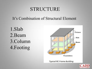
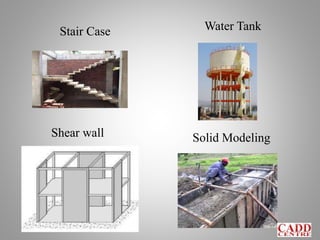
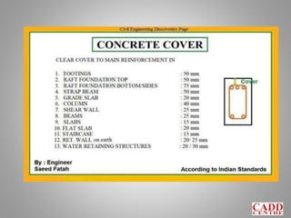
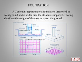
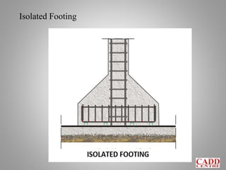
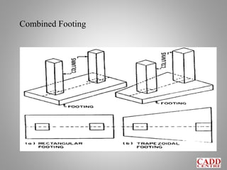
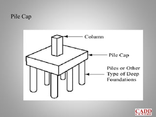
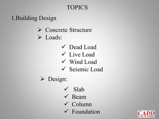
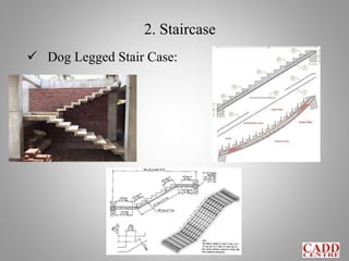
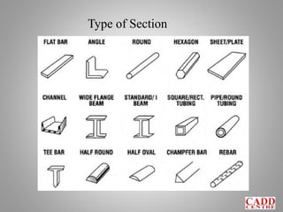
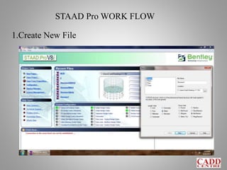
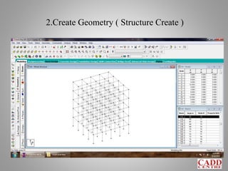
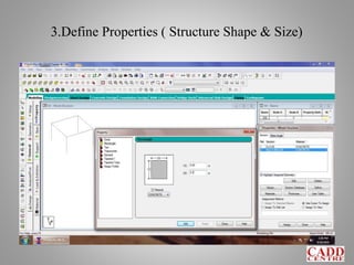
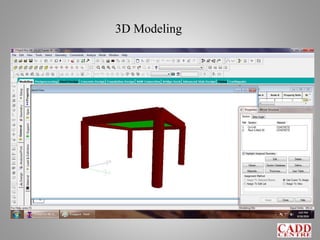
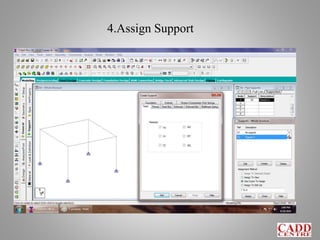
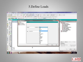
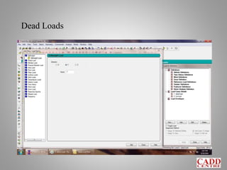
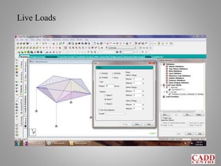
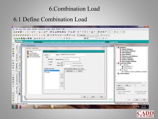
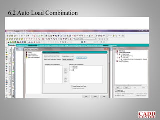
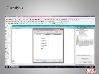
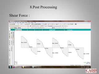
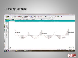
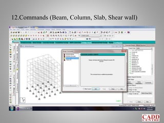
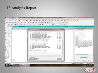
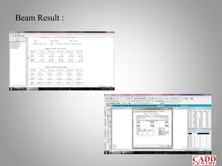
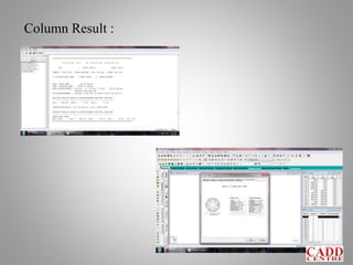
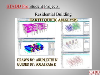
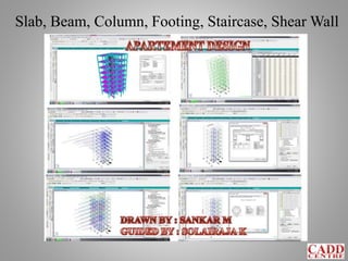
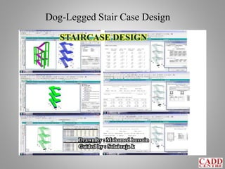
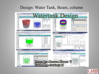
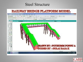
K.SOLAI RAJA.,B.E. (CIVIL)
DESIGN CADD ENGINEER
CADD CENTER DINDIGUL
WELCOME ENGINEER
STAAD PRO
80 Hr’s
Who is ?????
ST – Structural
A – Analysis
A – And
D – Design
Pro – Program
V8i – Version 2008 interactive
SS4 – Select Series4 (20.07.09.31)
STAAD Pro V8i
History of STAAD.Pro
 STAAD Pro was originally Developed by
Research Engineers International in Yorba
Linda, CA
 In late 2005, Research Engineer International
was bought by Bentley Systems.
Introduction to STAAD.Pro
 STAAD.Pro is a Structural Analysis Design Program
Software.
 It is used for 3D generation, analysis and multi-material
design.
 It’s a limit state method concept.
 It will create a framed structure only.
 This is the one and only structural engineering software.
 BEAVA – Bridge Engineering Automatic Vehicle Application
STRUCTURE
It’s Combination of Structural Element
1.Slab
2.Beam
3.Column
4.Footing
Solid Modeling
Stair Case Water Tank
Shear wall
Units
Length : Meter & Millimeter
Force : Kilo Newton & Newton
Load – KN/m Fc & Fe – N/mm2
STRUCTURE
 Real model – structural element .
 Physical model – modeling software .
 Mathematical model – STAAD pro design.
STRUCTURAL
Framed Structure : ( G+2 & above)
This Structure having the combination of
Beam, Column and Slab to resist the lateral and
gravity loads.
BASED ON LOADING
Load Bearing Structure : ( G+2 )
This Structure instead of
column and Beam, it has walls
taking the load.
BASED ON LOCATION
TYPE OF STRUCTURE
Aluminium.Timber
SteelConcrete
DESIGN
Architectural Design
Structural Design
Concrete : ( Fc - Compressive Stress)
Steel : ( fy - Tensile Stress)
Mild Steel – Fe 250
High Yield Strength Deformed Bars :
– Fe 415 & Fe 500
TMT – Thermo Mechanically Treated:
The TMT bars have a hard outer surface and a
softer core. Their manufacturing process includes hot
rolled steel wires passed through water
Partial Safety Factor for Material Strength (γm)
Characteristic Strength /
Partial Safety Factor for Strength (γm)
Design Strength =
Ultimate Limit State :
Concrete 1.50
Steel 1.15
Serviceability limits of deflection and cracking :
Ec = 5000 𝑓ck N/mm2
Es = 200 x 10^3 N/mm2
Ref: IS 456 :2000
Page No: 68
Class No: 36.4
Indian Standard Code Book
IS 456 – Reinforced Concrete Design
IS 800 – Steel Design
IS 802 – Transmission Tower ( I to III )
IS 875 – Dead Load ( Part I )
IS 875 – Live Load ( Part II )
IS 875 – Wind Load ( Part III )
IS 875 – Snow Load (Part IV )
IS 875 – Special Load (Part V )
IRC 6,18,21 – Bridge Design
IS 1893:1984 Criteria for Earthquake Resistant Design of
Structures
Part 1: General provisions and Buildings
Part 2: Liquid Retaining Tanks – Elevated and Ground Supported
Part 3 : Bridges and Retaining Walls
Part 4 : Industrial Structures Including Stack Like Structures
Part 5 : Dams and Embankments
Indian Standard Code Book
IS 3370 Code of practice Concrete structures for the storage
of liquids
Part 1: General requirements
Part 2: Reinforced concrete structures
Part 3: Prestressed Concrete Structures
Part 4: Design Tables
Number of Rod
8, 10, 12, 16, 18, 20, 22, 25, 28, 32, 36, 40, 45, 50 mm
UNIT WEIGHTS
R.C.C - 2500 KN/m3
P.C.C - 2400 KN/m3
Brick - 1800 KN/m3
Wood - (400-700) KN/m3
Soil - 1600 Kg/m3
Cement - 1440 Kg/m3
Stone - 2300 Kg/m3
Steel - 7850 Kg/m3
Glass - 2560 Kg/m3
Corse Aggregate – 2300 Kg/m3
Fine Aggregate – 2350 Kg/m3
1000 Liters = 1 m3
SLAB
1.One way Slab
2.Two Way Slab
ly / lx > 2
ly / lx < 2
BEAM
Horizontal Member & Tension Member
Basic Value of Span to effective depth
ratios for spans up to 10m
 Cantilever 7
 Simple Supported 20
 Continuous 26
above 10 m
le /10 to le /15
Ref: IS 456 :2000
Page No: 37
Class No: 23.2.1
COLUMN
Vertical Member & Compression Member
Ref: IS 456 :2000
Page No: 41
Class No: 25.1.2
Short Column
l eff / LLD > 12
Long Column
l eff / LLD < 12
Minimum Eccentricity
IS456, Clause 25.4 gives an expression for
the possible min. eccentricity
emin = ( L / 500 ) + ( D / 30)
but not less then 20 mm
FOUNDATION
A Concrete support under a foundation that rested in
solid ground and is wider than the structure supported. Footing
distribute the weight of the structure over the ground.
Isolated Footing
Combined Footing
Pile Cap
Mat Footing
1.Point Load
Various Forms Load :
2.UDL (uniform Distribution Load )
2. Trapezoidal Load
3.UVL (uniform variable load)
1. Triangle Load
Dead Load : Framing, Flooring & Roofing
Materials, Plumbing, HVAC etc.,
Load type with Example
Live Load : Weight of Persons, Movable
Partitions, Dust Load, Weight of Furniture etc.,
Wind Load : Thrust of Wind on High-rise
Structure etc.,
Snow Load : Accumulated Snow over Roof.
Wave Load : Impact of Waves on Walls or
Bridge Pillar
EarthQuake Load : Forces Caused due to
Horizontal / Vertical Movement of Building
Construction Load : Shoring, Scaffolding,
Brick Stored at First Floor, Construction
equipments kept on floor, etc.,
Earth Pressure : Retaining wall with soil as
backfill etc.,
Water Pressure : Water tank, Dam, etc.,
Thermal Load : Rise in Stress due to increase
in indoor temperature etc.,
Creep : Creep in Concrete
Machine Vibration Load : Jumping, Walking,
Dropping Vibrations due to Machine, etc.,
Corrosion : Fatigue Stress in Steel etc.,
TOPICS
1.Building Design
 Concrete Structure
 Loads:
 Dead Load
 Live Load
 Wind Load
 Seismic Load
 Design:
 Slab
 Beam
 Column
 Foundation
2. Staircase
 Dog Legged Stair Case:
 Circular Stair Case:
3. Water Tank
 Ground Water Tank
 Over Head Water Tank
 Under Ground Water Tank
LOCATION:
TYPE:
 Rectangular Water Tank
 Square Water Tank
 Circular Water Tank
Water Tank STAAD Pro Model
R.C.C Detailing Water Tank
4. Shear Wall
Shear Wall Examples:
1. Lift Wall
2. Jail Compound Wall
3. Retaining Wall
4. Under Ground Structure Wall
5. Earth Quick Resistant Wall
6. Bank Lockers
5. Solid Model
Embankment Structure
Solid Model Examples:
1.Dams
2.Lake
3.Pond
4.Field Ground
6. Steel Structure
Type of Section
Transmission Tower
STAAD Pro WORK FLOW
1.Create New File
2.Create Geometry ( Structure Create )
3.Define Properties ( Structure Shape & Size)
3D Modeling
4.Assign Support
5.Define Loads
Dead Loads
Live Loads
6.Combination Load
6.1 Define Combination Load
6.2 Auto Load Combination
7.Analysis
8.Post Processing
Shear Force :
Bending Moment :
Displacement :
9.Design
10.Choose Code Book
11.Define parameter
12.Commands (Beam, Column, Slab, Shear wall)
13.Analysis Report
Beam Result :
Column Result :
14.Report Create :
How to Create a Model in STAAD Pro :
1. Snap / Grid – Graphical Method
2. Data Sheet – Excel Sheet
3.STAAD Editor – Program Method
4.Structure Wizard – Separate Method
4.Structure Wizard – Type of Models
5.DXF Import – Auto CAD to STADD Pro
STADD Pro Student Projects:
Residential Building
Slab, Beam, Column, Footing, Staircase, Shear Wall
Dog-Legged Stair Case Design
Design: Water Tank, Beam, column
Steel Structure
Vehicle Load for Small Bridge
BEAVA Application
STAAD Pro Models:
STAAD Pro Models:
STAAD Pro Models:
STAAD Pro Models:
Thank You.,
Any Questions ???

Staad Pro Intro