Download as PDF, PPTX


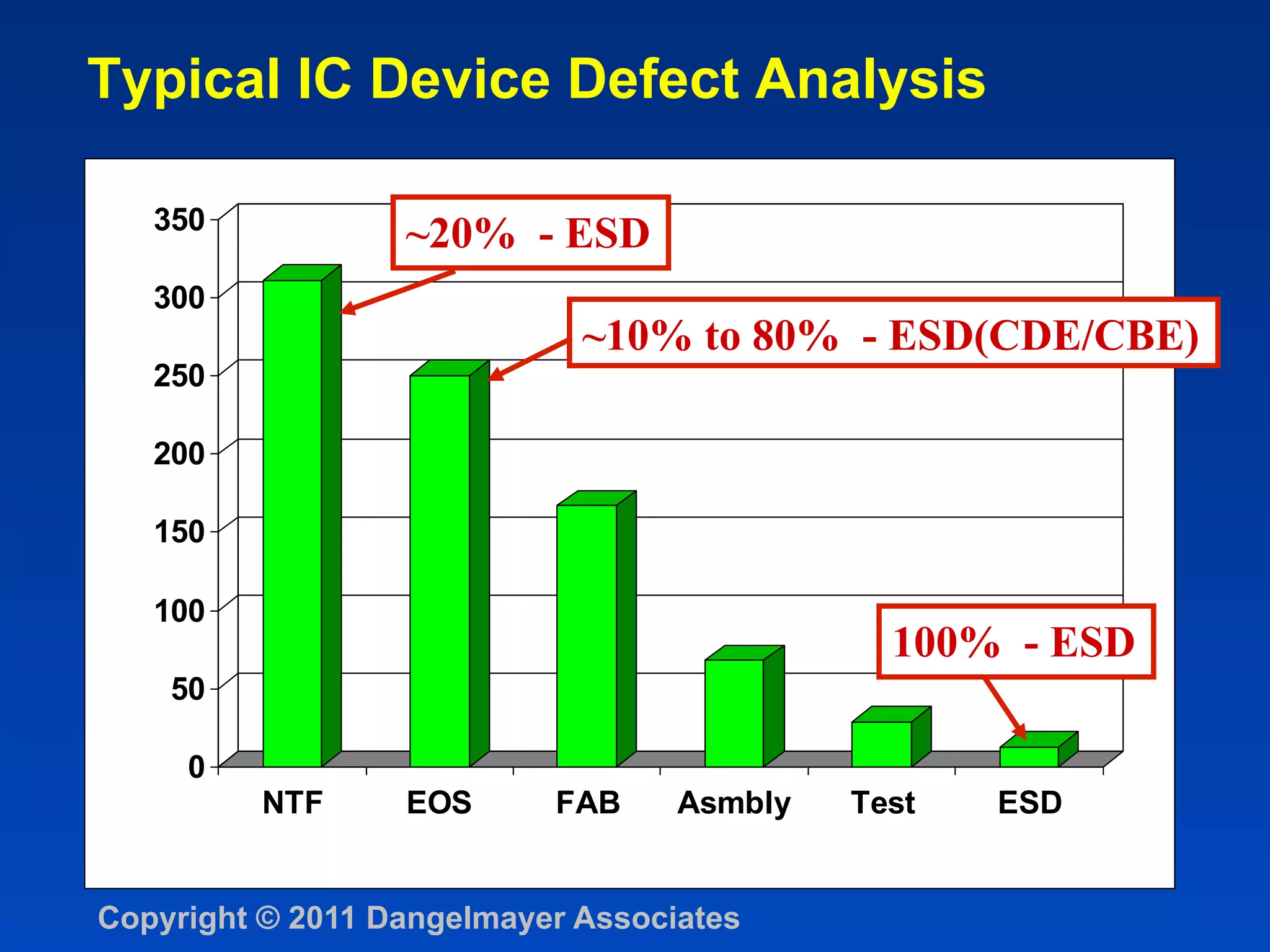
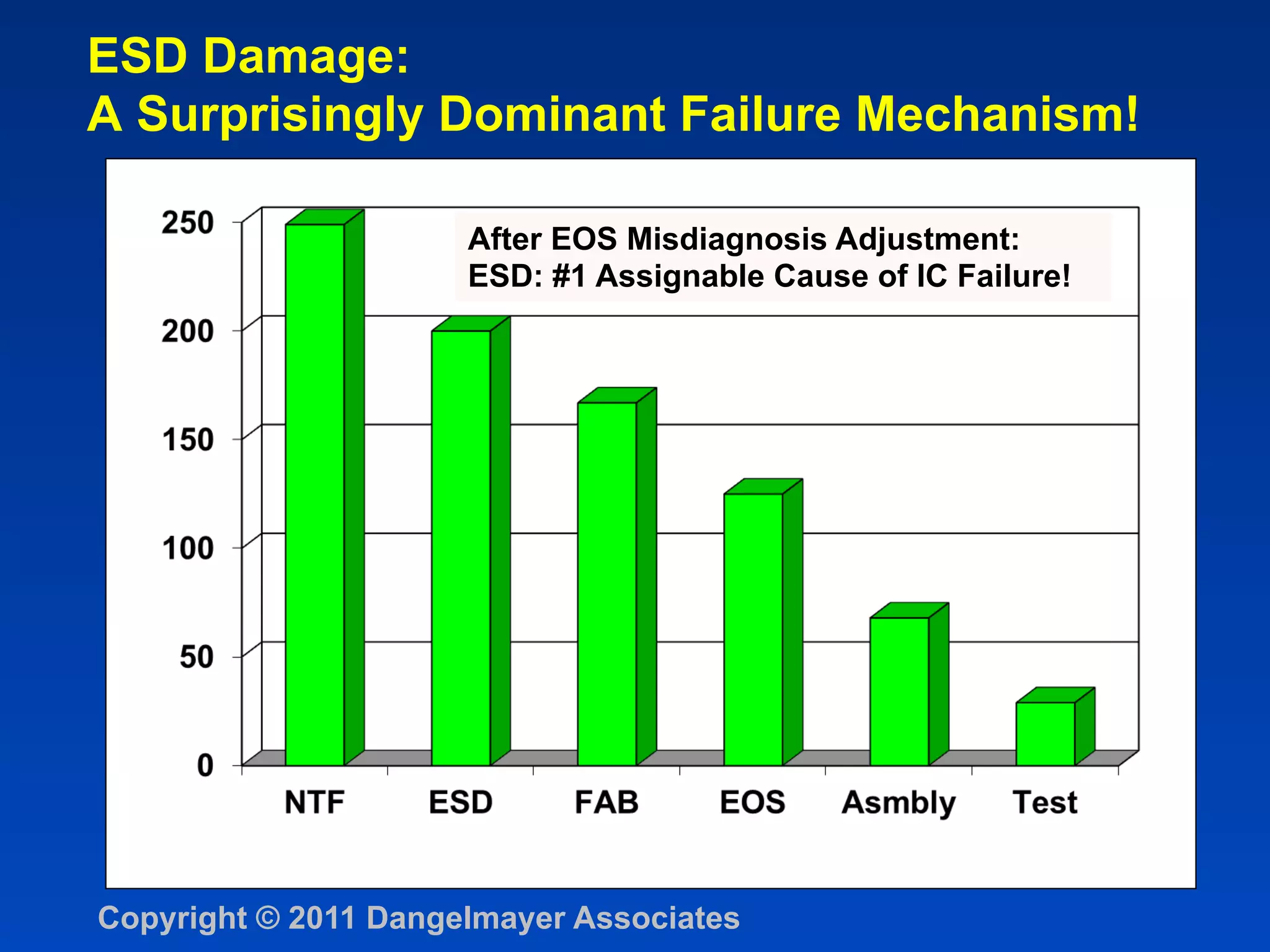
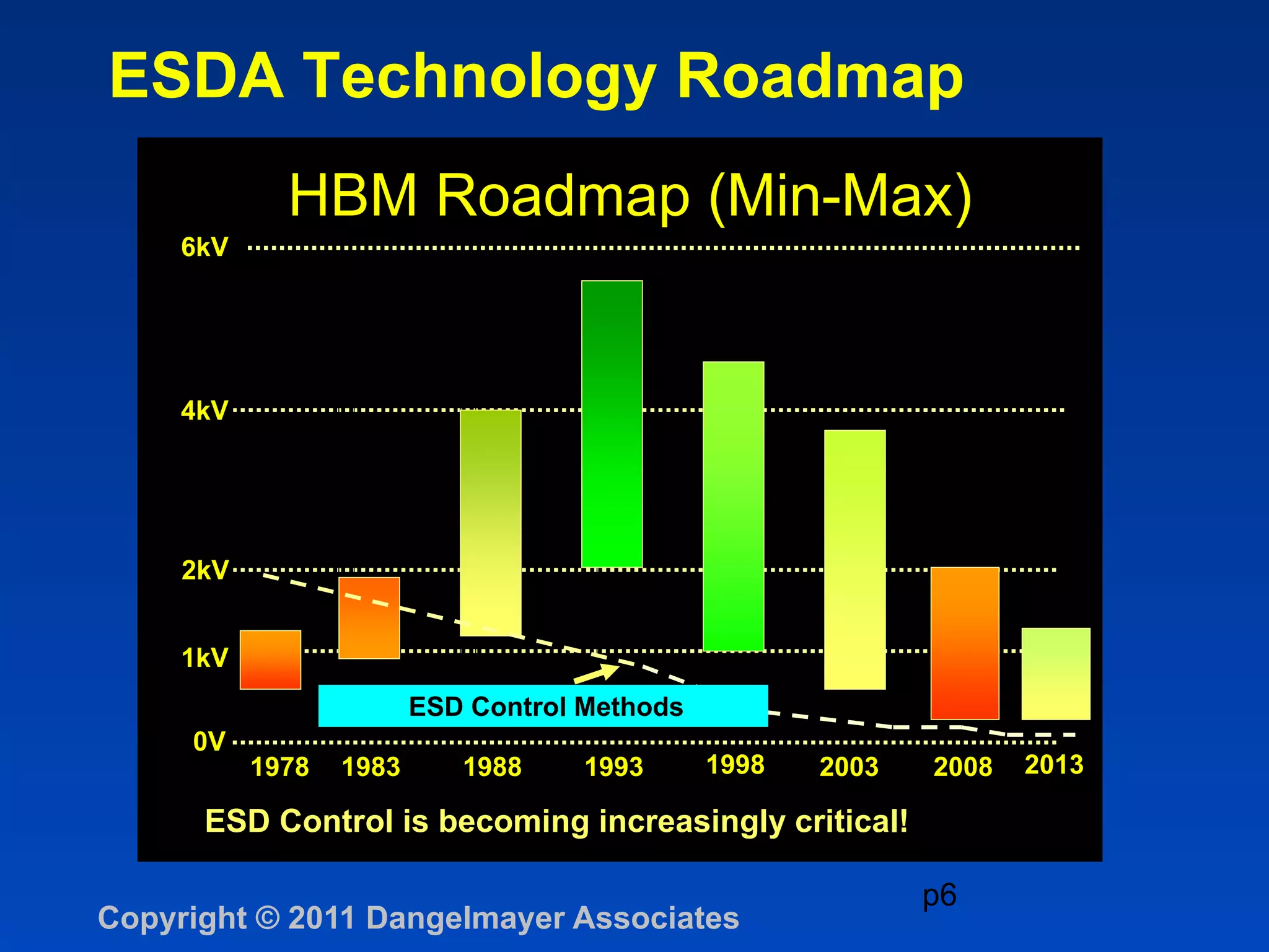
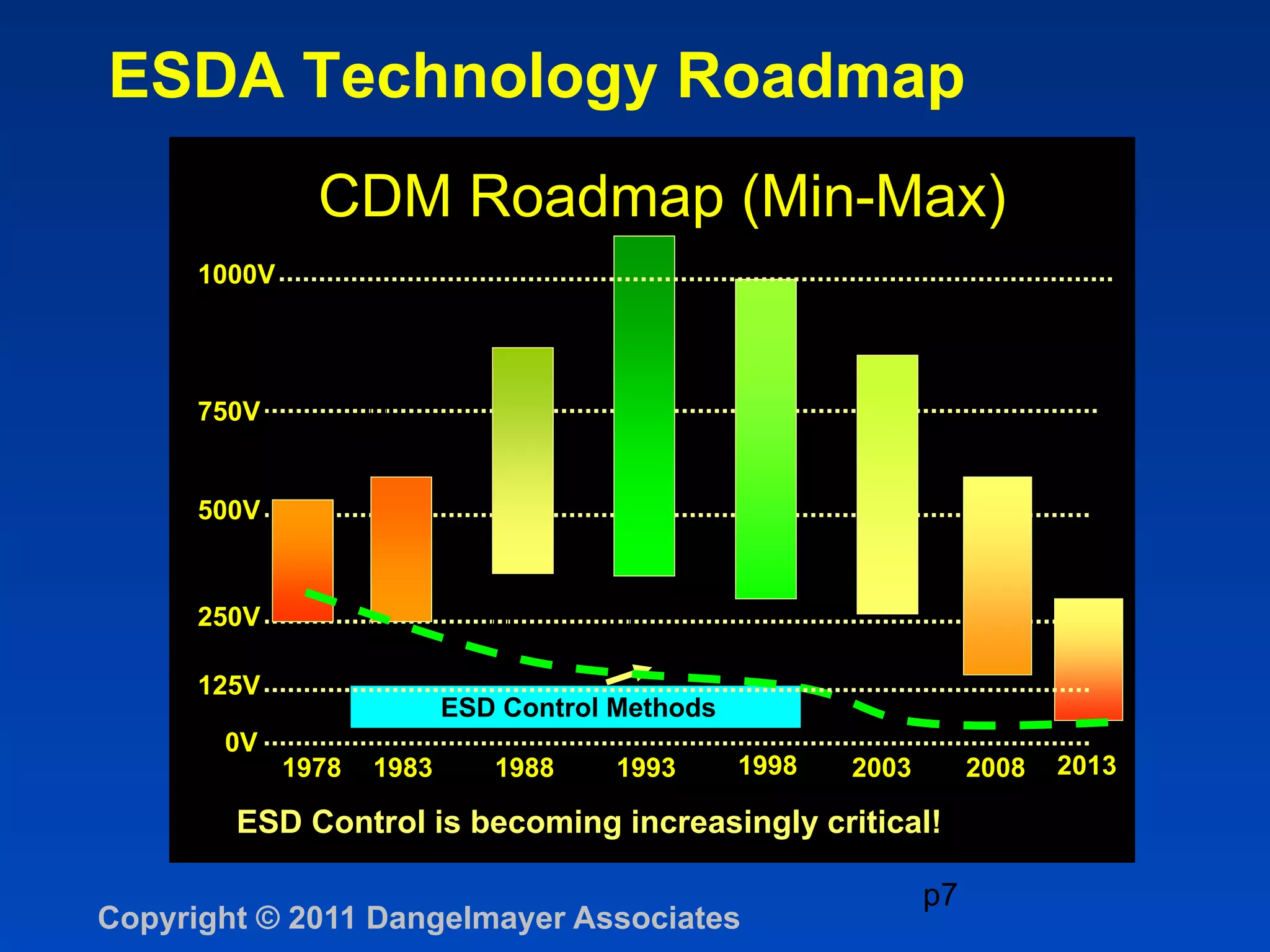
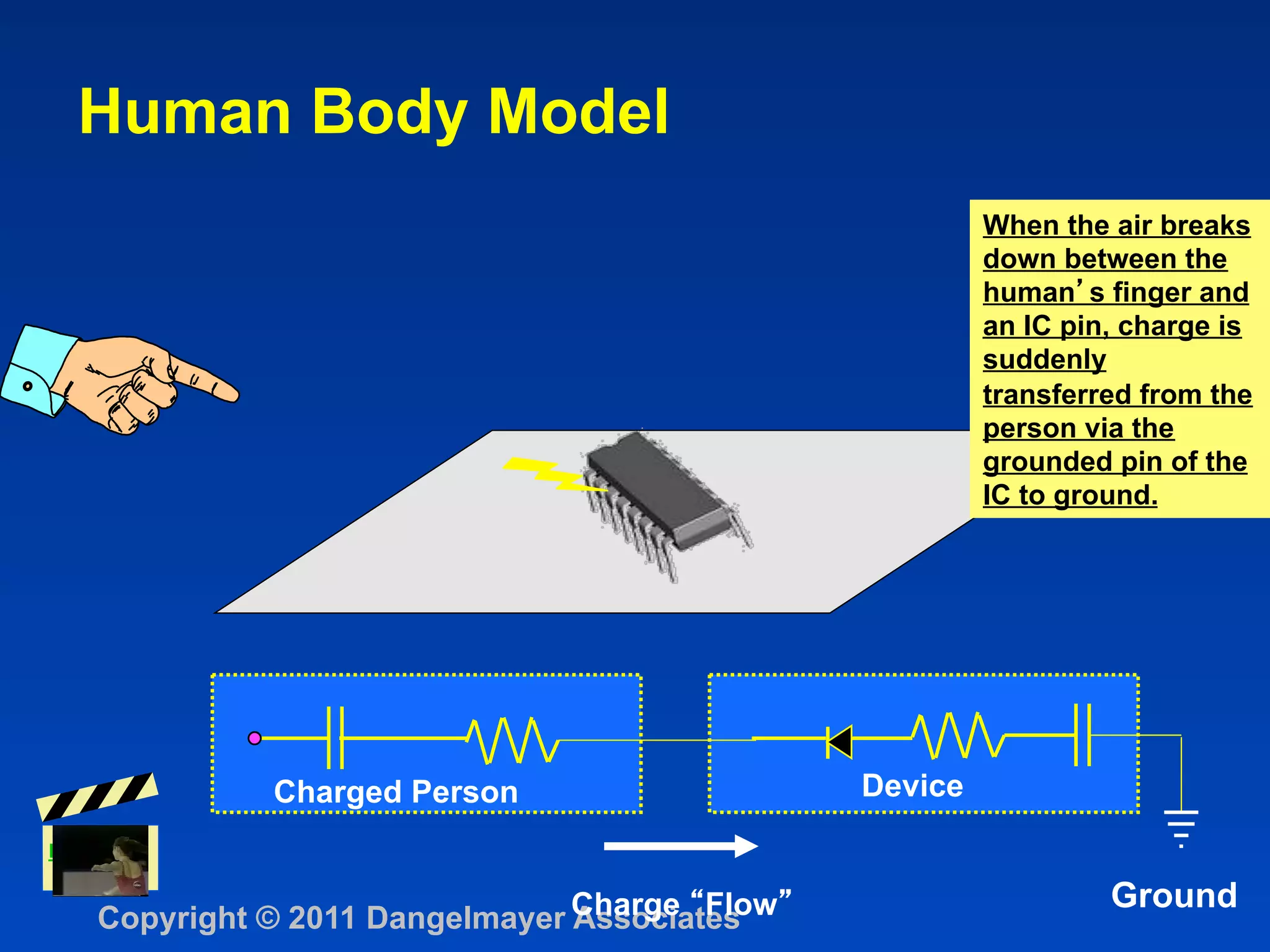
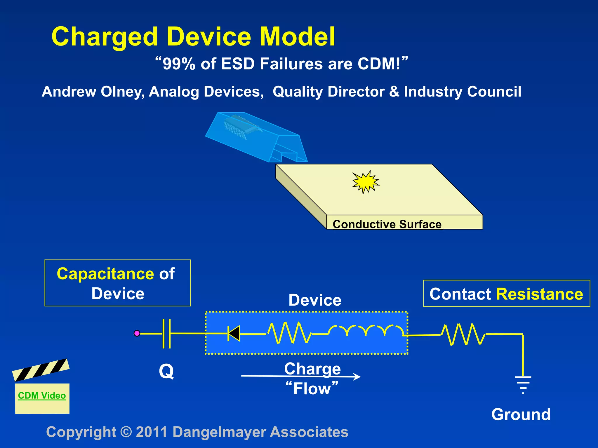
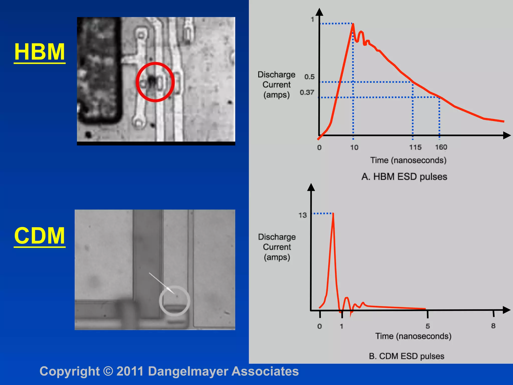
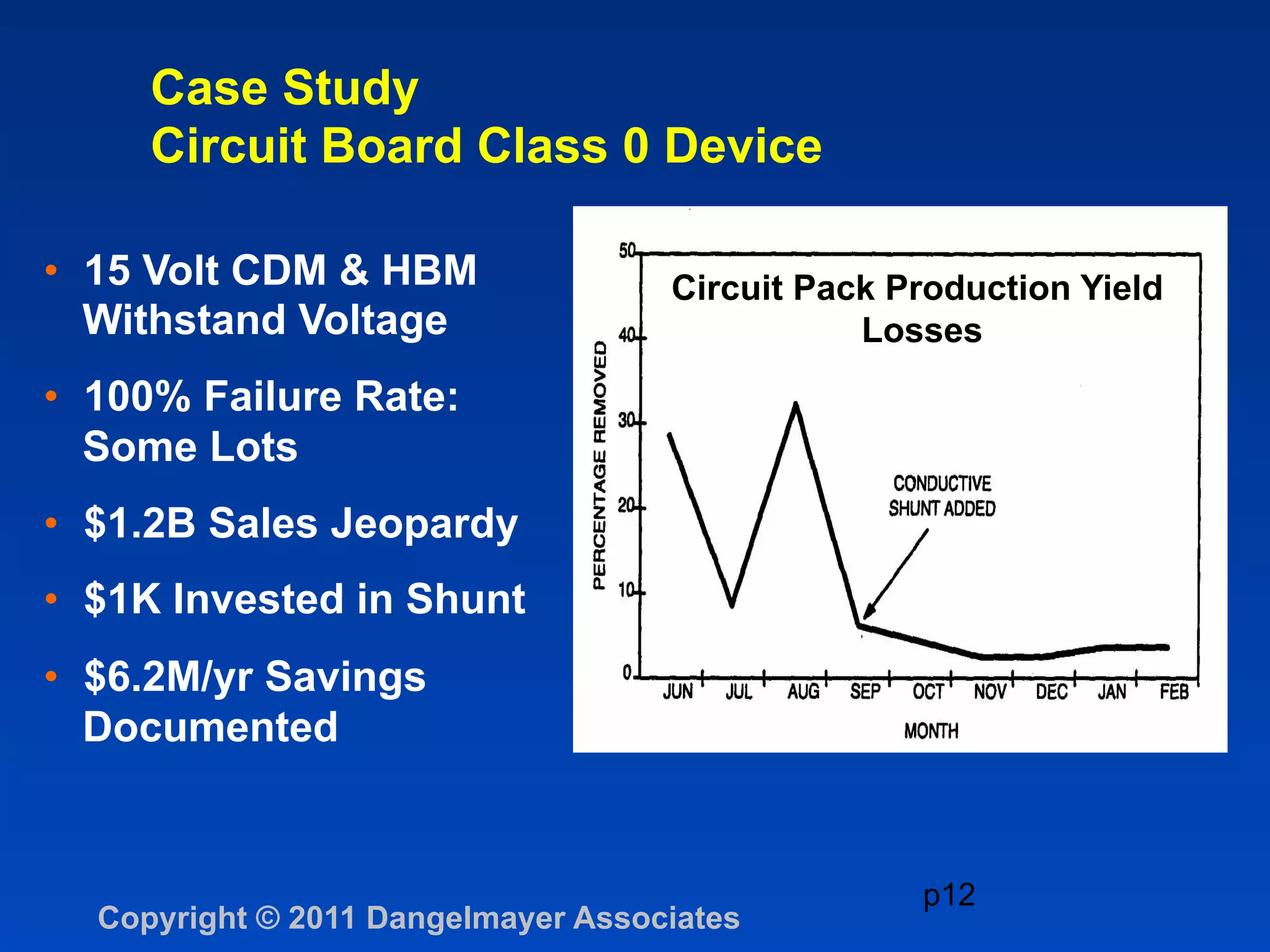
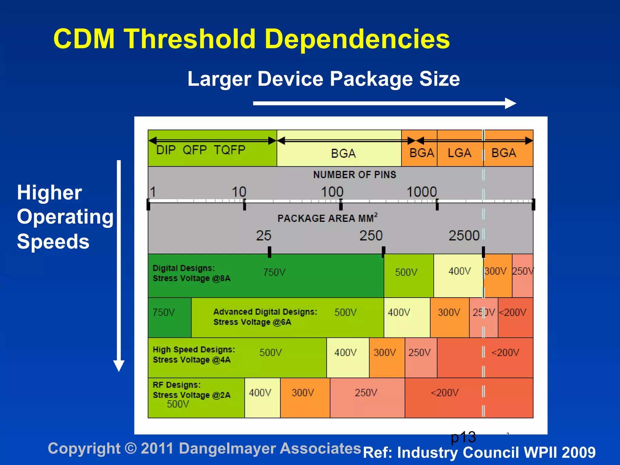
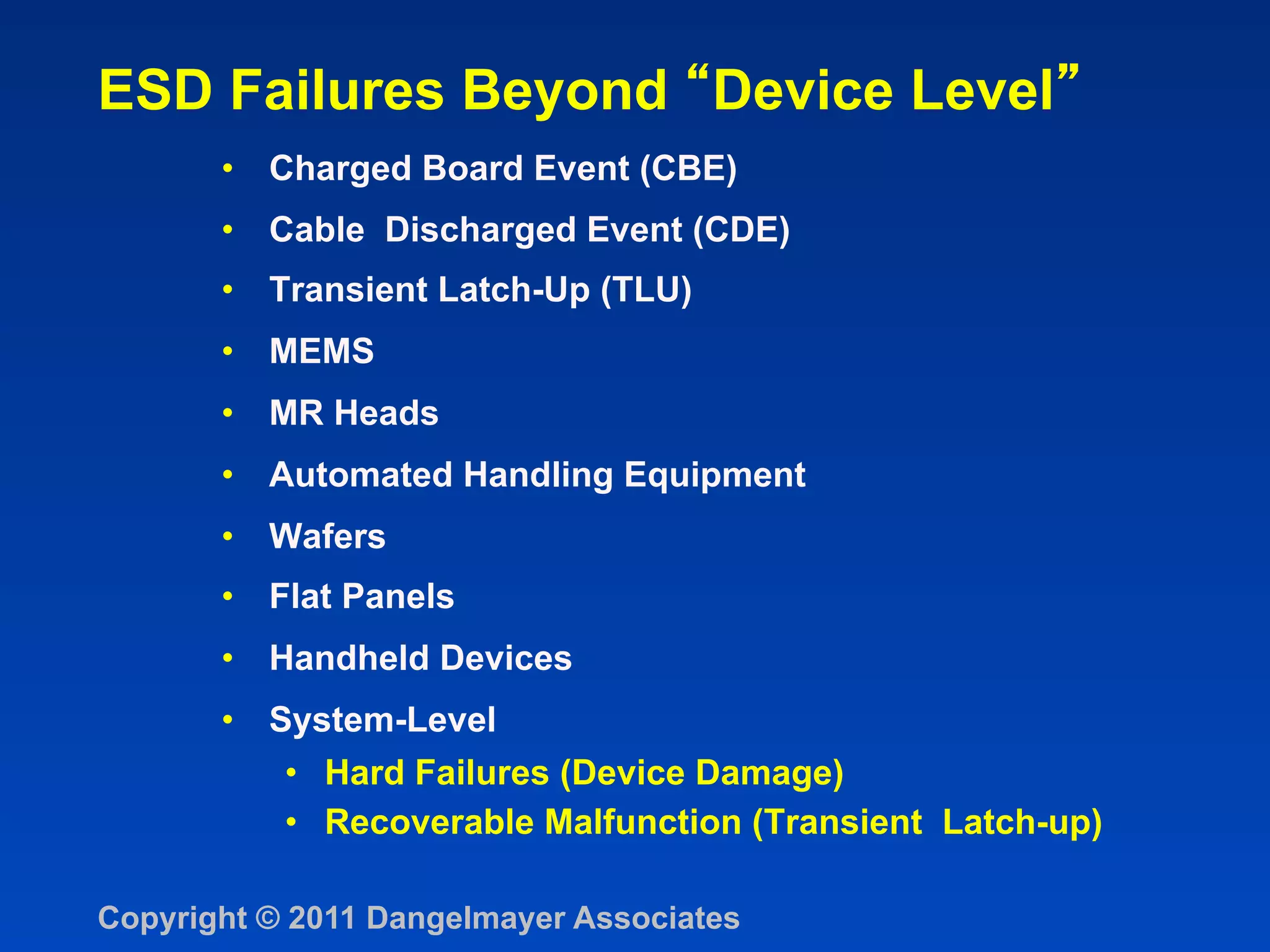
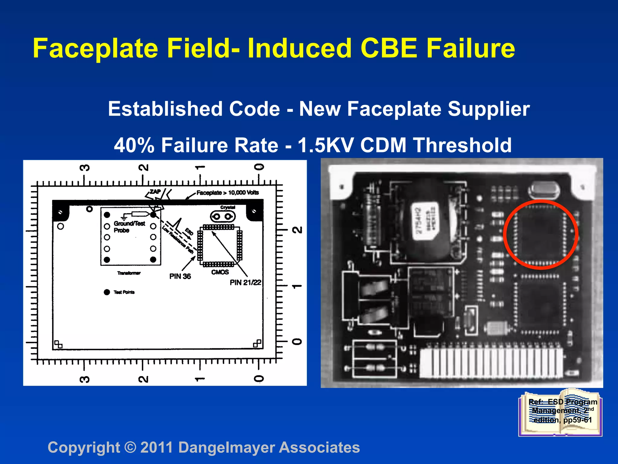
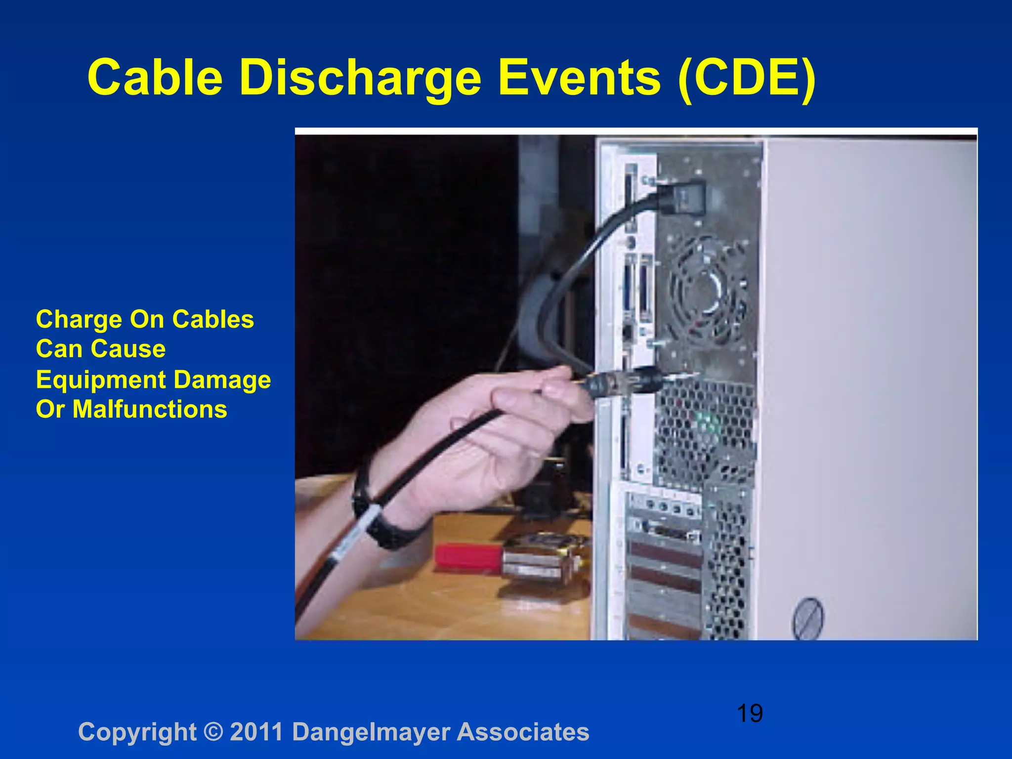
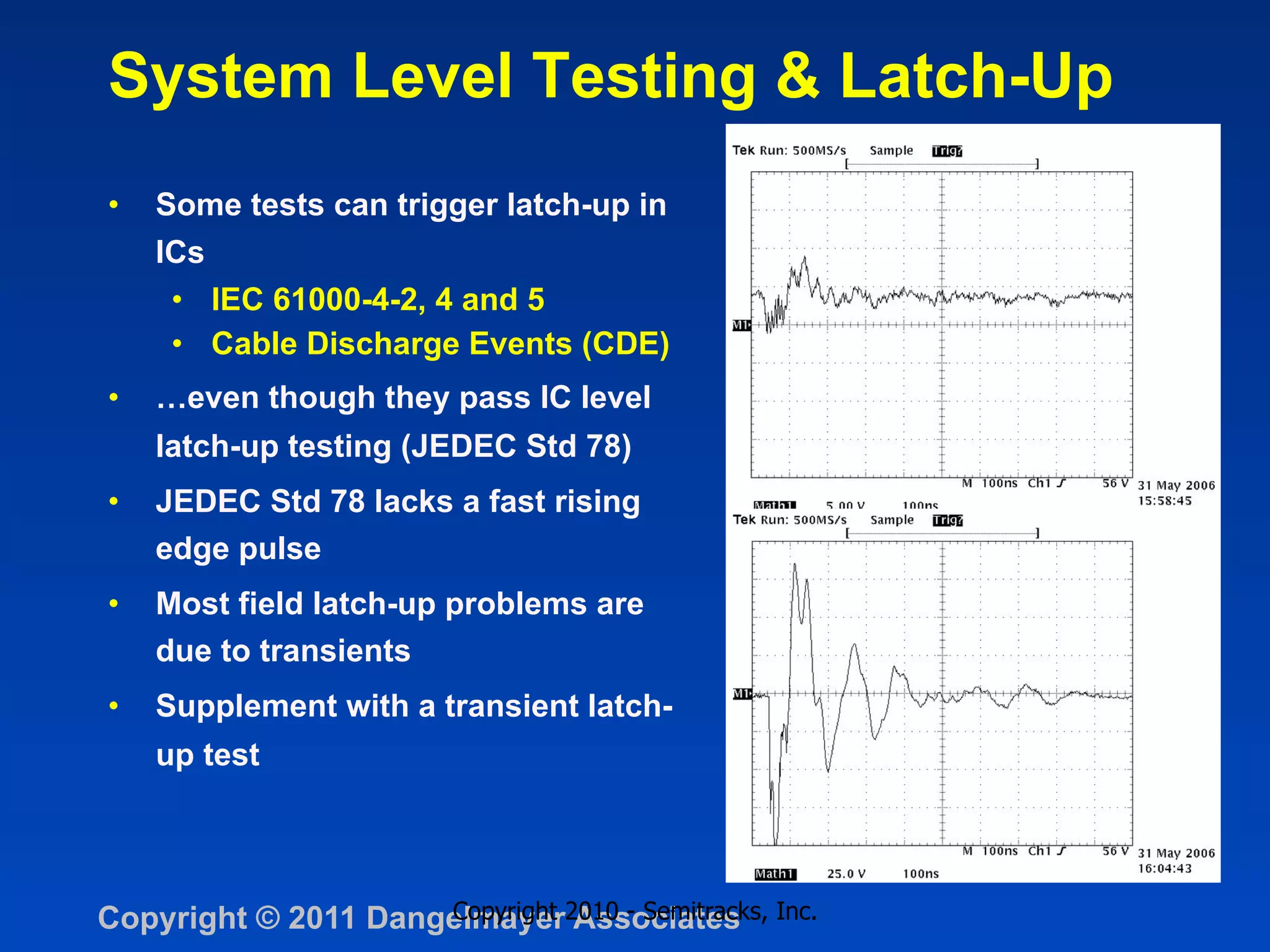
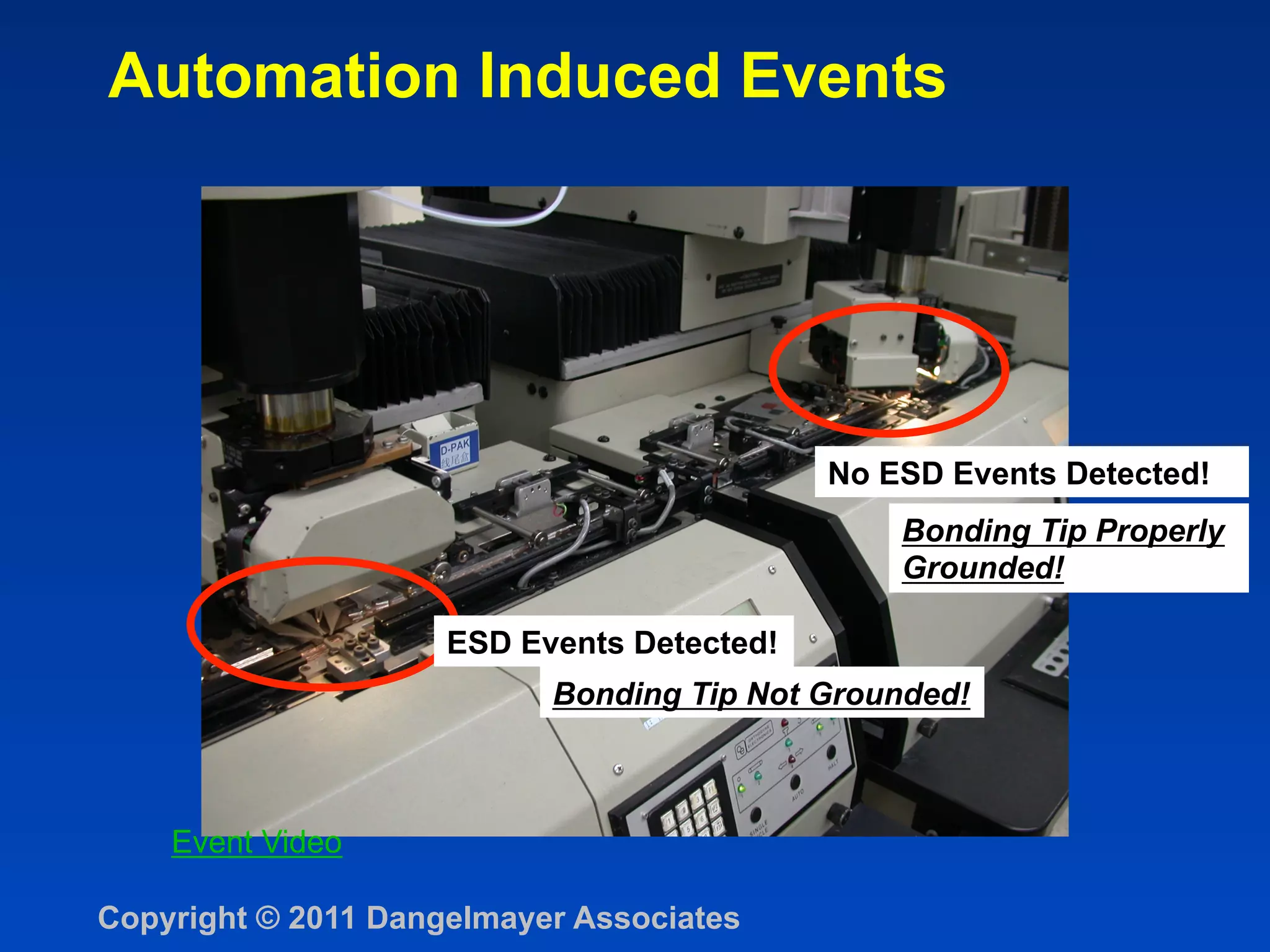

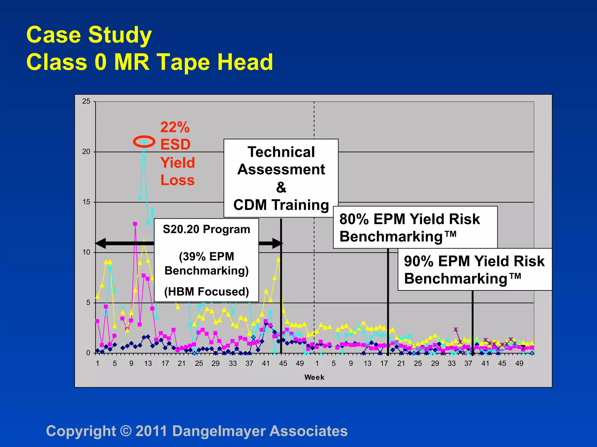
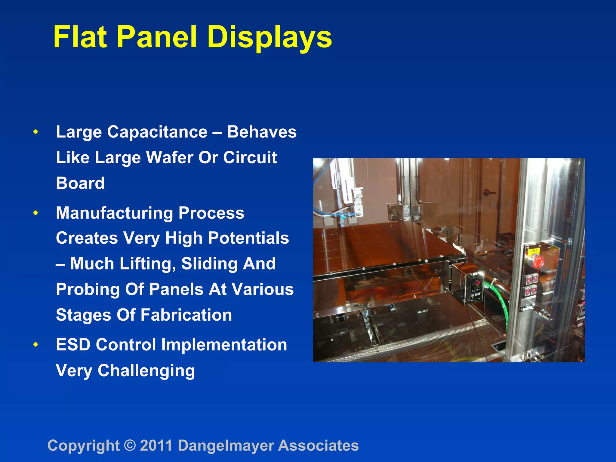
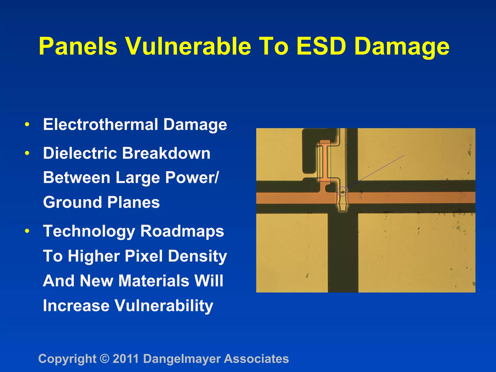
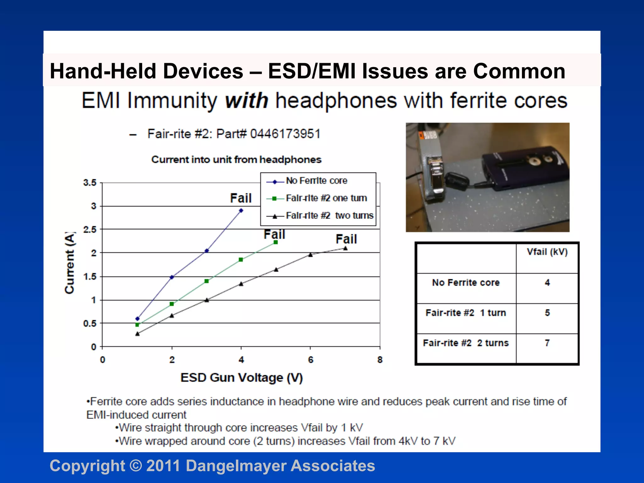
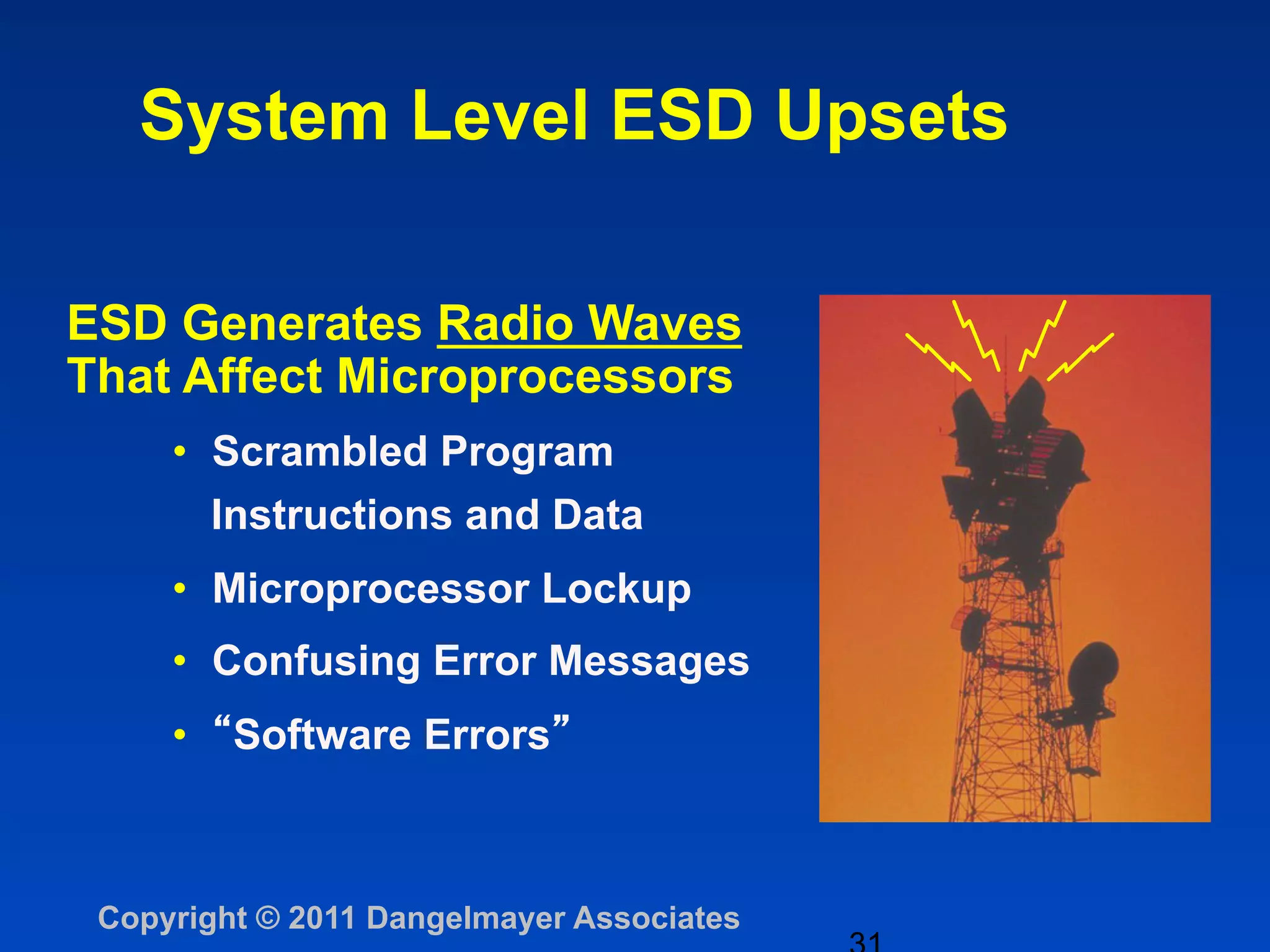


The document discusses the significant impact of electrostatic discharge (ESD) on product quality and reliability, identifying it as a leading cause of integrated circuit failures. It presents trends in ESD sensitivity, reviews different discharge models, and outlines the necessity for effective ESD countermeasures across various device types and assembly processes. Key findings include the importance of addressing failures beyond the device level, including charged board events and system-level testing, as part of ESD management strategies.


![Vibe Coding vs. Spec-Driven Development [Free Meetup]](https://cdn.slidesharecdn.com/ss_thumbnails/vibecodingvsspecdrivendevelopment-251209105622-43f455e7-thumbnail.jpg?width=640&height=640&fit=bounds)


![Coded Agents – with UiPath SDK + LangGraph [Virtual Hands-on Workshop]](https://cdn.slidesharecdn.com/ss_thumbnails/codedagentsdeck-251215155422-5497c599-thumbnail.jpg?width=640&height=640&fit=bounds)


