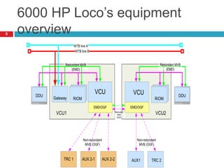
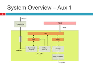
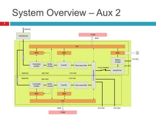
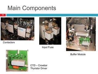
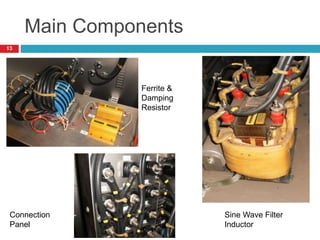
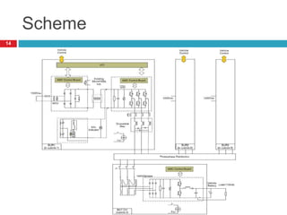
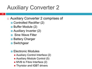
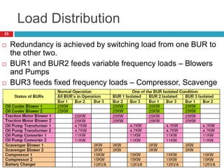
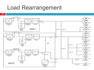
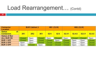
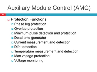
AUXILIARY
CONVERTER
Vishal M J, Traction Engineering
1
Auxiliary System
 Features
 System Overview
 Main Components
 Scheme
 Normal Operation
 Frequency Control
 Voltage Control
 Converter Structure
 Load Distribution & Re-arrangement
 Power Modules
 CREC, Buffer Module, ACPS, LVPS
 Electronic Modules
 ACI, AMC, AGC-T, AGC-I
2
Features
 CREC, ACPS, LVPS and Buffer Module –
exchangeable units, have same control board
 All modules contained in a cabinet having IP65
protection
 Sine Wave Filter and Transformer mounted in
IP20 enclosures
 Heat sink at the rear, service access in the
front
 Field replaceable units
 Remote diagnostics possible
3
Electrics for E-Loco
The Electrical equipment for loco consists of:
 Two Water cooled Traction Converters with 3 independent Motor Side
inverters
 AUX. Converter - 1 with 1*130 kVA inverter
 AUX. Converter - 2 with 2*130 kVA inverter and 11 kW battery charger
 2 Vehicle Control Units
4
6000 HP Loco’s equipment
overview
VCU VCU
TRC 1
DDU DDU
AUX 2-1 AUX 2-2
Non-redundant
MVB (OGF)
Redundant MVB
(EMD)
Redundant
MVB
(OGF)
Gateway
WTB line A
WTB line B
RIOM
RIOM
RIOM RIOM
RIOM
RIOM
Non-redundant
MVB (OGF)
EMD/OGF EMD/OGF
Redundant MVB
(EMD)
VCU1 VCU2
AUX1 TRC 2
5
System Overview – Aux 1
Buffer-
module
Controlled
rectifier
Inverter
Transformer
25kVAC
AMC AMC
ACI
TCMS
MVB
Sine wave filter
1000VAC
625 VDC
415 VAC
6
System Overview – Aux 2
Buffer-
module
Controlled
rectifier
Inverter
Transformer
25kVAC
AMC AMC
ACI
TCMS
MVB
1000VAC 625 VDC
415 VAC
Battery
charger
transformer
415 VAC
AMC AMC
Controlled
rectifier
Buffer-
module
Inverter
ACI
Sine wave filter
Sine wave filter
Circuit breaker
AMC
TCMS
MVB
415V
distribution
415 VAC
140 VAC
110 VDC
625 VDC 415 VAC
1000VAC
Tbat
Ubat
7
System Overview… (Contd)
 Supplied from the 1000V auxiliary winding of
the traction transformer
 3 Auxiliary converters installed. On failure of
one of the auxiliary converter, load will be
redistributed
 DC Link Inductor (part of transformer) used
 Thyristor based controlled rectifier and IGBT
based 3 phase inverter
8
Main Components - BUR
BUR1, BUR2 and BUR3 are identical. Each
Converter contains:
 Single Phase 1000V/50HZ input terminals
 Input Fuse
 Controlled Rectifier (Fully Controlled Thyristor
bridge)
 DC Link Inductor (part of transformer)
 Discharge Resistor for DC Link
 HV indicator
9
Main Components – BUR…
(Contd)
 Buffer Capacitor
 Overvoltage protection – Autonomous crowbar
 Three-Phase IGBT based inverter, 130kVA
 Three phase output filter (for THD<5%)
 Three phase output terminals, 415V/50Hz
10
Main Components – Battery
Charger
 The battery charger consists of:
 Three phase insulating transformer
 Three phase circuit breaker
 Chopper Controlled battery Charger 12kW, 111V,
110A
11
Main Components
Contactors
Input Fuse
Buffer Module
CTD – Crowbar
Thyristor Driver
12
Main Components
Connection
Panel
Sine Wave Filter
Inductor
Ferrite &
Damping
Resistor
13
Scheme
14
Normal Operation
 Each converter generates a symmetrical 3
phase sine wave voltage with low harmonic
distortion
 Aux1 and Aux2 output frequency can be
controlled to a maximum of 50Hz (while
maintaining V/f constant)
 Aux 3 – Output voltage is 415V and frequency
is 50Hz (fixed frequency loads)
 At low output frequency operation – V/f is
slightly made high to assist speeding of motors
with high startup torque
15
Frequency Control
 VCU can change the output frequency in 3
steps – 24Hz, 37Hz and 50Hz (At present only
37Hz & 50Hz available)
 V/f is maintained constant – Motors do operate
normally
 Panto bounce – Frequency will be temporarily
reduced to make use of the stored energy in
running motors. Buffer module capacitors is
the source for extra reserve energy.
16
Voltage Control
 DC link is primarily controlled by CREC
 Voltage Feedback is from a sensor which is
connected to the DC Link
 CREC features an onboard synchronization
transformer
 Self supporting unit – in case of an overload,
rectifier will reduce the output voltage
 For better control of heavy motors at low
frequency, voltage boost feature is
incorporated for Auxiliary Inverter
17
Converter Structure
 Modular Design
 Power Modules are contained in a well sealed
(IP65) compartment
 Modules have heat sink at the rear, cooled by
forced air
18
Converter Structure – Front
View
19
Converter Structure – Rear
View
20
Auxiliary Converter 1
21
Auxiliary Converter 2
22
Auxiliary Converter 1
 Auxiliary Converter 1 comprises of
 Controlled Rectifier (1)
 Buffer Module (1)
 Auxiliary Inverter (1)
 Sine Wave Filter
 Electronic Modules
 Auxiliary Control Interface (1)
 Auxiliary Module Control (2)
 MVB to Fibre Interface (1)
 Thyristor and IGBT drivers
23
Auxiliary Converter 2
 Auxiliary Converter 2 comprises of
 Controlled Rectifier (2)
 Buffer Module (2)
 Auxiliary Inverter (2)
 Sine Wave Filter
 Battery Charger
 Switchgear
 Electronic Modules
 Auxiliary Control Interface (2)
 Auxiliary Module Control (5)
 MVB to Fibre Interface (2)
 Thyristor and IGBT drivers
24
Load Distribution
 Redundancy is achieved by switching load from one BUR to
the other two.
 BUR1 and BUR2 feeds variable frequency loads – Blowers
and Pumps
 BUR3 feeds fixed frequency loads – Compressor, Scavenge
Blower
25
Load Rearrangement
26
Load Rearrangement… (Contd)
27
Controlled Rectifier - CREC
 Converts 1Ph 1000Vac into
controlled DC voltage of 700V
 CREC comprises of
 MOV for over voltage
protection
 Synchronization voltage
sensor
 Thyristors and Snubber
 Thyristor driver (AGC-T)
 AMC Control Board
 Temperature sensor (Heat
28
Controlled Rectifier - CREC
 Completely
independent unit,
requires only a power
supply
 External
communication with a
vehicle network via ACI
 Robust Design
 Protected against over
load, over voltage (i/p &
o/p), DC Link short
circuit and over
29
Buffer Module
 Stores electric energy – line
interruption ride through
 Capacitive buffer
 Contains autonomous
crowbar – protection against
over-voltages
 CTD operates when DC
voltage exceeds 1000V
 Main Parts are
 Buffer capacitor
 Crowbar + Associated trigger
ckt
30
Buffer Module… (Contd)
31
Auxiliary Inverter - ACPS
 Converts DC Link
voltage into 3Ph PWM
sine wave voltage
 Voltage & Frequency
can be independently
controlled
 Localized protections,
implemented in AMC
32
Auxiliary Inverter – ACPS.. (Contd)
 Main components of the
ACPS are
 Three phase-leg IGBT
modules
 AMC Board
 Three AGC-I control boards
 DC Link capacitors
 Discharge Resistor
 Heat sink temperature
sensor
 Three Output current
33
ACPS – Normal Operation
 Inverter will start as soon as the DC voltage
exceeds minimum start value
 Voltage and Frequency will rise with constant
rate (while maintaining V/f constant)
 Output voltage is controlled by modulation
index
 Output frequency is controlled by frequency
modulation
34
Battery Charger - LVPS
 Input voltage supply is an isolated 3Ph
140Vrms/50Hz voltage
 Forced air cooled module
 Includes 3Ph Diode bridge rectifier and a down
chopper
 Has one AMC board for control
35
Main Component List
 Controlled Rectifier
 Buffer Module
36
Main Component List… (Contd)
 Auxiliary Inverter
 Battery Charger
37
Auxiliary Control Interface (ACI)
 Interface between Auxiliary
Modules (AMC) and the
vehicle (VCU)
 Has three processing units:
 DSP – runs control and
regulation tasks
 Microcontroller – runs
communication and support
tasks
 FPGA – several interfaces
and timing tasks
38
Auxiliary Module Control (AMC)
 Used for control of Auxiliary
converter modules
 Three processor boards
 DSP – control and regulation tasks
 Microcontroller – runs communication
and support tasks
 FPGA – interfaces, timing tasks and
phase leg protection
 Control functions configurable by
software
 Main functions are
 Protection of auxiliary converter
modules
 Pulse generation
 Control of Auxiliary modules
39
Auxiliary Module Control (AMC)
 Protection Functions
 Phase leg protection
 Overlap protection
 Minimum pulse detection and protection
 Dead time generator
 Current measurement and detection
 Di/dt detection
 Temperature measurement and detection
 Max voltage protection
 Voltage monitoring
40
MVB to Fiber Interface (MFI)
 Interfaces electrical signals
of the MVB bus with optic
signals
 One electrical MVB
connection and max 5 optical
MVB connections
41
Auxiliary Gate Controller (AGC-
T)
 Driver stages for controlling
the two thyristor modules
 Control electronics through
10 pin flat cable connector
 Power supply and control
signals galvanically isolated
 Compact and rugged –
Maintenance free and easily
replaceable unit
42
Auxiliary Gate Controller (AGC-
I)
 Used to control a
Semikron Semix IGBT
module
 Driver stages for
controlling two IGBTs of
an IGBT module
 Mounted directly on IGBT
 di/dt control
 High speed short-circuit
detection
 Control electronics
43

AuxCnv.ppsx

  • 1.
    AUXILIARY CONVERTER Vishal M J,Traction Engineering 1
  • 2.
    Auxiliary System  Features System Overview  Main Components  Scheme  Normal Operation  Frequency Control  Voltage Control  Converter Structure  Load Distribution & Re-arrangement  Power Modules  CREC, Buffer Module, ACPS, LVPS  Electronic Modules  ACI, AMC, AGC-T, AGC-I 2
  • 3.
    Features  CREC, ACPS,LVPS and Buffer Module – exchangeable units, have same control board  All modules contained in a cabinet having IP65 protection  Sine Wave Filter and Transformer mounted in IP20 enclosures  Heat sink at the rear, service access in the front  Field replaceable units  Remote diagnostics possible 3
  • 4.
    Electrics for E-Loco TheElectrical equipment for loco consists of:  Two Water cooled Traction Converters with 3 independent Motor Side inverters  AUX. Converter - 1 with 1*130 kVA inverter  AUX. Converter - 2 with 2*130 kVA inverter and 11 kW battery charger  2 Vehicle Control Units 4
  • 5.
    6000 HP Loco’sequipment overview VCU VCU TRC 1 DDU DDU AUX 2-1 AUX 2-2 Non-redundant MVB (OGF) Redundant MVB (EMD) Redundant MVB (OGF) Gateway WTB line A WTB line B RIOM RIOM RIOM RIOM RIOM RIOM Non-redundant MVB (OGF) EMD/OGF EMD/OGF Redundant MVB (EMD) VCU1 VCU2 AUX1 TRC 2 5
  • 6.
    System Overview –Aux 1 Buffer- module Controlled rectifier Inverter Transformer 25kVAC AMC AMC ACI TCMS MVB Sine wave filter 1000VAC 625 VDC 415 VAC 6
  • 7.
    System Overview –Aux 2 Buffer- module Controlled rectifier Inverter Transformer 25kVAC AMC AMC ACI TCMS MVB 1000VAC 625 VDC 415 VAC Battery charger transformer 415 VAC AMC AMC Controlled rectifier Buffer- module Inverter ACI Sine wave filter Sine wave filter Circuit breaker AMC TCMS MVB 415V distribution 415 VAC 140 VAC 110 VDC 625 VDC 415 VAC 1000VAC Tbat Ubat 7
  • 8.
    System Overview… (Contd) Supplied from the 1000V auxiliary winding of the traction transformer  3 Auxiliary converters installed. On failure of one of the auxiliary converter, load will be redistributed  DC Link Inductor (part of transformer) used  Thyristor based controlled rectifier and IGBT based 3 phase inverter 8
  • 9.
    Main Components -BUR BUR1, BUR2 and BUR3 are identical. Each Converter contains:  Single Phase 1000V/50HZ input terminals  Input Fuse  Controlled Rectifier (Fully Controlled Thyristor bridge)  DC Link Inductor (part of transformer)  Discharge Resistor for DC Link  HV indicator 9
  • 10.
    Main Components –BUR… (Contd)  Buffer Capacitor  Overvoltage protection – Autonomous crowbar  Three-Phase IGBT based inverter, 130kVA  Three phase output filter (for THD<5%)  Three phase output terminals, 415V/50Hz 10
  • 11.
    Main Components –Battery Charger  The battery charger consists of:  Three phase insulating transformer  Three phase circuit breaker  Chopper Controlled battery Charger 12kW, 111V, 110A 11
  • 12.
    Main Components Contactors Input Fuse BufferModule CTD – Crowbar Thyristor Driver 12
  • 13.
    Main Components Connection Panel Sine WaveFilter Inductor Ferrite & Damping Resistor 13
  • 14.
  • 15.
    Normal Operation  Eachconverter generates a symmetrical 3 phase sine wave voltage with low harmonic distortion  Aux1 and Aux2 output frequency can be controlled to a maximum of 50Hz (while maintaining V/f constant)  Aux 3 – Output voltage is 415V and frequency is 50Hz (fixed frequency loads)  At low output frequency operation – V/f is slightly made high to assist speeding of motors with high startup torque 15
  • 16.
    Frequency Control  VCUcan change the output frequency in 3 steps – 24Hz, 37Hz and 50Hz (At present only 37Hz & 50Hz available)  V/f is maintained constant – Motors do operate normally  Panto bounce – Frequency will be temporarily reduced to make use of the stored energy in running motors. Buffer module capacitors is the source for extra reserve energy. 16
  • 17.
    Voltage Control  DClink is primarily controlled by CREC  Voltage Feedback is from a sensor which is connected to the DC Link  CREC features an onboard synchronization transformer  Self supporting unit – in case of an overload, rectifier will reduce the output voltage  For better control of heavy motors at low frequency, voltage boost feature is incorporated for Auxiliary Inverter 17
  • 18.
    Converter Structure  ModularDesign  Power Modules are contained in a well sealed (IP65) compartment  Modules have heat sink at the rear, cooled by forced air 18
  • 19.
  • 20.
  • 21.
  • 22.
  • 23.
    Auxiliary Converter 1 Auxiliary Converter 1 comprises of  Controlled Rectifier (1)  Buffer Module (1)  Auxiliary Inverter (1)  Sine Wave Filter  Electronic Modules  Auxiliary Control Interface (1)  Auxiliary Module Control (2)  MVB to Fibre Interface (1)  Thyristor and IGBT drivers 23
  • 24.
    Auxiliary Converter 2 Auxiliary Converter 2 comprises of  Controlled Rectifier (2)  Buffer Module (2)  Auxiliary Inverter (2)  Sine Wave Filter  Battery Charger  Switchgear  Electronic Modules  Auxiliary Control Interface (2)  Auxiliary Module Control (5)  MVB to Fibre Interface (2)  Thyristor and IGBT drivers 24
  • 25.
    Load Distribution  Redundancyis achieved by switching load from one BUR to the other two.  BUR1 and BUR2 feeds variable frequency loads – Blowers and Pumps  BUR3 feeds fixed frequency loads – Compressor, Scavenge Blower 25
  • 26.
  • 27.
  • 28.
    Controlled Rectifier -CREC  Converts 1Ph 1000Vac into controlled DC voltage of 700V  CREC comprises of  MOV for over voltage protection  Synchronization voltage sensor  Thyristors and Snubber  Thyristor driver (AGC-T)  AMC Control Board  Temperature sensor (Heat 28
  • 29.
    Controlled Rectifier -CREC  Completely independent unit, requires only a power supply  External communication with a vehicle network via ACI  Robust Design  Protected against over load, over voltage (i/p & o/p), DC Link short circuit and over 29
  • 30.
    Buffer Module  Storeselectric energy – line interruption ride through  Capacitive buffer  Contains autonomous crowbar – protection against over-voltages  CTD operates when DC voltage exceeds 1000V  Main Parts are  Buffer capacitor  Crowbar + Associated trigger ckt 30
  • 31.
  • 32.
    Auxiliary Inverter -ACPS  Converts DC Link voltage into 3Ph PWM sine wave voltage  Voltage & Frequency can be independently controlled  Localized protections, implemented in AMC 32
  • 33.
    Auxiliary Inverter –ACPS.. (Contd)  Main components of the ACPS are  Three phase-leg IGBT modules  AMC Board  Three AGC-I control boards  DC Link capacitors  Discharge Resistor  Heat sink temperature sensor  Three Output current 33
  • 34.
    ACPS – NormalOperation  Inverter will start as soon as the DC voltage exceeds minimum start value  Voltage and Frequency will rise with constant rate (while maintaining V/f constant)  Output voltage is controlled by modulation index  Output frequency is controlled by frequency modulation 34
  • 35.
    Battery Charger -LVPS  Input voltage supply is an isolated 3Ph 140Vrms/50Hz voltage  Forced air cooled module  Includes 3Ph Diode bridge rectifier and a down chopper  Has one AMC board for control 35
  • 36.
    Main Component List Controlled Rectifier  Buffer Module 36
  • 37.
    Main Component List…(Contd)  Auxiliary Inverter  Battery Charger 37
  • 38.
    Auxiliary Control Interface(ACI)  Interface between Auxiliary Modules (AMC) and the vehicle (VCU)  Has three processing units:  DSP – runs control and regulation tasks  Microcontroller – runs communication and support tasks  FPGA – several interfaces and timing tasks 38
  • 39.
    Auxiliary Module Control(AMC)  Used for control of Auxiliary converter modules  Three processor boards  DSP – control and regulation tasks  Microcontroller – runs communication and support tasks  FPGA – interfaces, timing tasks and phase leg protection  Control functions configurable by software  Main functions are  Protection of auxiliary converter modules  Pulse generation  Control of Auxiliary modules 39
  • 40.
    Auxiliary Module Control(AMC)  Protection Functions  Phase leg protection  Overlap protection  Minimum pulse detection and protection  Dead time generator  Current measurement and detection  Di/dt detection  Temperature measurement and detection  Max voltage protection  Voltage monitoring 40
  • 41.
    MVB to FiberInterface (MFI)  Interfaces electrical signals of the MVB bus with optic signals  One electrical MVB connection and max 5 optical MVB connections 41
  • 42.
    Auxiliary Gate Controller(AGC- T)  Driver stages for controlling the two thyristor modules  Control electronics through 10 pin flat cable connector  Power supply and control signals galvanically isolated  Compact and rugged – Maintenance free and easily replaceable unit 42
  • 43.
    Auxiliary Gate Controller(AGC- I)  Used to control a Semikron Semix IGBT module  Driver stages for controlling two IGBTs of an IGBT module  Mounted directly on IGBT  di/dt control  High speed short-circuit detection  Control electronics 43