Downloaded 133 times


![Program:
#include <90s8535.h>
unsigned int timecount=0;
interrupt [TIM0_OVF] void time0_ovf_isr(void)
{
TCNT0=6;
if(++timecount==2)
{
PORTA=PORTA^0x80;
timecount=0;
}
}
void main(void)
{
DDRA=0x80;
TCCR0=0x02;
TCNT0=0x00;
TIMSK=0x01;
#asm("sei");
while (1)
{
};
}](https://image.slidesharecdn.com/practicalmanual1-150323101836-conversion-gate01/85/Embedded-System-Practical-manual-1-10-320.jpg)


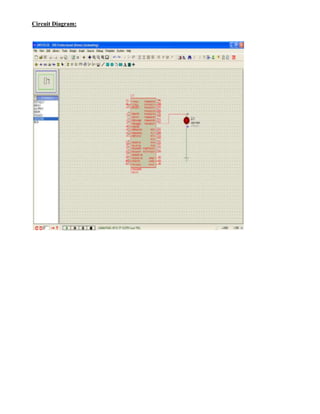
![Program:
#include <90s8535.h>
unsigned int timecount=0;
interrupt[TIM0_OVF] void timeo_ovf_isr(void)
{
TCNT0 = 6;
if(++timecount==2)
{
PORTA=PORTA^0x80;
timecount=0;
}
}
void main(void)
{
DDRA = 0x80;
TCCR0 = 0x02;
TCNT0 = 0x00;
TIMSK = 0x01;
#asm("sei");
while (1)
{
};
}](https://image.slidesharecdn.com/practicalmanual1-150323101836-conversion-gate01/85/Embedded-System-Practical-manual-1-16-320.jpg)


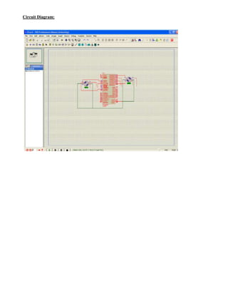
![Program:
#include <90s8535.h>
int count = 9, i ;
int arrValuesHigh[] = {245, 245, 246, 246, 247, 247, 248, 248, 249, 249, 250, 250, 251, 251,
252, 252, 253, 253, 254, 254, 255, 255} ;
int arrValuesLow[] = {0, 0, 0, 0, 1, 1, 2, 2, 3, 3, 4, 4, 5, 5, 6, 6, 7, 7, 8, 8, 9, 9} ;
void main(void)
{
PORTA=0xFF;
DDRA=0xFF;
while (1)
{
if(count == 9)
{
for(i=0 ; i<22 ; i++)
{
PORTA = arrValuesLow[i] ;
}
for(count=9 ; count!=245 ; count++)
{
PORTA = count ;
}
for(i=0 ; i<22 ; i++)
{
PORTA = arrValuesHigh[i] ;
}
}
if(count == 245)
{
for(i=21 ; i>=0 ; i--)
{
PORTA = arrValuesHigh[i] ;
}
for(count=245 ; count!=9 ; count--)
{
PORTA = count ;
}
for(i=21 ; i>=0 ; i--)
{
PORTA = arrValuesLow[i] ;
}
}
};}](https://image.slidesharecdn.com/practicalmanual1-150323101836-conversion-gate01/85/Embedded-System-Practical-manual-1-23-320.jpg)


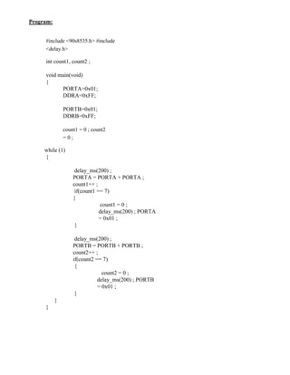
![Program:
#include <90s8535.h>
#define pulse_out PORTC
#define ICP PIND.6
unsigned char ov_counter;
unsigned int rising_edge,falling_edge;
unsigned long pulse_clocks;
interrupt [TIM1_OVF]timer1_ovf_isr(void)
{
ov_counter++;
}
interrupt [TIM1_CAPT] void timer1_capt_isr(void)
{
if(ICP)
{
rising_edge=ICR1;
TCCR1B=TCCR1B &
0xBF; ov_counter=0;
}
else
{
falling_edge=ICR1;
TCCR1B=TCCR1B | 0x40;
pulse_clocks=(unsigned long)falling_edge-(unsigned
long)rising_edge+(unsigned long)ov_counter *100000;
pulse_out=pulse_clocks;
}
}
void main(void)
{
PORTA=0x00;
DDRA=0x00;
PORTB=0x00;
DDRB=0x00;
DDRC=0xff;
TCCR1B=0xc2;](https://image.slidesharecdn.com/practicalmanual1-150323101836-conversion-gate01/85/Embedded-System-Practical-manual-1-34-320.jpg)


![Program:
#include <90s8535.h>
interrupt [EXT_INT0] void ext_int0_isr(void)
{
PORTA=PORTA ^ 0x01;
}
void main(void)
{
PORTB=0x01;
DDRB=0x01;
DDRA=0x01;
GIMSK=0x40;
MCUCR=0x02;
#asm("sei");
while (1)
{
};
}](https://image.slidesharecdn.com/practicalmanual1-150323101836-conversion-gate01/85/Embedded-System-Practical-manual-1-38-320.jpg)

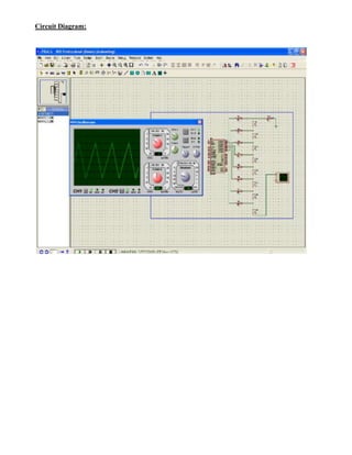
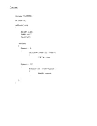
This document contains details of 11 practical experiments conducted using an AT90S8535 microcontroller. Each experiment is summarized in 3 sentences or less: 1. Toggle the state of LEDs connected to two ports by alternately setting the ports high and low with a 0.5 second delay. 2. Simulate an 8-bit binary counter by incrementing the port value and lighting LEDs one by one with a 0.2 second delay. 3. Generate a 1 second delay by toggling an LED connected to one port using a timer overflow interrupt that increments a counter.