Downloaded 304 times
![DHT11
www.researchdesignlab.com Page 9
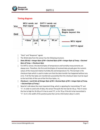
CODE
/* DHT library
*/
#include "DHT.h"
DHT::DHT(uint8_t pin, uint8_t type) {
_pin = pin;
_type = type;
firstreading = true;
}
void DHT::begin(void) {
// set up the pins!
pinMode(_pin, INPUT);
digitalWrite(_pin, HIGH);
_lastreadtime = 0;
}
//boolean S == Scale. True == Farenheit; False == Celcius
float DHT::readTemperature(bool S) {
float f;
if (read()) {
switch (_type) {
case DHT11:
f = data[2];
if(S)
f = convertCtoF(f);
return f;
case DHT22:
case DHT21:
f = data[2] & 0x7F;
f *= 256;
f += data[3];
f /= 10;
if (data[2] & 0x80)
f *= -1;
if(S)
f = convertCtoF(f);
return f;
}
}](https://image.slidesharecdn.com/dht11-151005103213-lva1-app6892/85/DHT11-Digital-Temperature-and-Humidity-Sensor-9-320.jpg)
![DHT11
www.researchdesignlab.com Page 10
Serial.print("Read fail");
return NAN;
}
float DHT::convertCtoF(float c) {
return c * 9 / 5 + 32;
}
float DHT::readHumidity(void) {
float f;
if (read()) {
switch (_type) {
case DHT11:
f = data[0];
return f;
case DHT22:
case DHT21:
f = data[0];
f *= 256;
f += data[1];
f /= 10;
return f;
}
}
Serial.print("Read fail");
return NAN;
}
boolean DHT::read(void) {
uint8_t laststate = HIGH;
uint8_t counter = 0;
uint8_t j = 0, i;
unsigned long currenttime;
// pull the pin high and wait 250 milliseconds
digitalWrite(_pin, HIGH);
delay(250);
currenttime = millis();
if (currenttime < _lastreadtime) {
// ie there was a rollover
_lastreadtime = 0;
}
if (!firstreading && ((currenttime - _lastreadtime) < 2000)) {
return true; // return last correct measurement
//delay(2000 - (currenttime - _lastreadtime));
}
firstreading = false;](https://image.slidesharecdn.com/dht11-151005103213-lva1-app6892/85/DHT11-Digital-Temperature-and-Humidity-Sensor-10-320.jpg)
![DHT11
www.researchdesignlab.com Page 11
/*
Serial.print("Currtime: "); Serial.print(currenttime);
Serial.print(" Lasttime: "); Serial.print(_lastreadtime);
*/
_lastreadtime = millis();
data[0] = data[1] = data[2] = data[3] = data[4] = 0;
// now pull it low for ~20 milliseconds
pinMode(_pin, OUTPUT);
digitalWrite(_pin, LOW);
delay(20);
cli();
digitalWrite(_pin, HIGH);
delayMicroseconds(40);
pinMode(_pin, INPUT);
// read in timings
for ( i=0; i< MAXTIMINGS; i++) {
counter = 0;
while (digitalRead(_pin) == laststate) {
counter++;
delayMicroseconds(1);
if (counter == 255) {
break;
}
}
laststate = digitalRead(_pin);
if (counter == 255) break;
// ignore first 3 transitions
if ((i >= 4) && (i%2 == 0)) {
// shove each bit into the storage bytes
data[j/8] <<= 1;
if (counter > 6)
data[j/8] |= 1;
j++;
}
}
sei();
/*
Serial.println(j, DEC);
Serial.print(data[0], HEX); Serial.print(", ");
Serial.print(data[1], HEX); Serial.print(", ");
Serial.print(data[2], HEX); Serial.print(", ");](https://image.slidesharecdn.com/dht11-151005103213-lva1-app6892/85/DHT11-Digital-Temperature-and-Humidity-Sensor-11-320.jpg)
![DHT11
www.researchdesignlab.com Page 12
Serial.print(data[3], HEX); Serial.print(", ");
Serial.print(data[4], HEX); Serial.print(" =? ");
Serial.println(data[0] + data[1] + data[2] + data[3], HEX);
*/
// check we read 40 bits and that the checksum matches
if ((j >= 40) &&
(data[4] == ((data[0] + data[1] + data[2] + data[3]) & 0xFF)) )
{
return true;
}
return false;
}
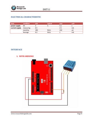
LIBRARY
This is the library function that need to be added to the library
#if ARDUINO >= 100
#include "Arduino.h"
#else
#include "WProgram.h"
#endif
/* DHT library
*/
// how many timing transitions we need to keep track of. 2 * number
bits + extra
#define MAXTIMINGS 85
#define DHT11 11
#define DHT22 22
#define DHT21 21
#define AM2301 21
class DHT {
private:
uint8_t data[6];
uint8_t _pin, _type;
boolean read(void);
unsigned long _lastreadtime;
boolean firstreading;](https://image.slidesharecdn.com/dht11-151005103213-lva1-app6892/85/DHT11-Digital-Temperature-and-Humidity-Sensor-12-320.jpg)

The DHT11 is a digital temperature and humidity sensor that offers calibrated output, high reliability, and low power consumption, with measuring ranges of 20-90% RH for humidity and 0-50°C for temperature. The sensor utilizes a specific data transfer protocol with a microcontroller, delivering data in a 40-bit format that includes relative humidity and temperature values, along with a checksum for error verification. Various specifications, including power requirements and communication methods, are outlined, alongside example Arduino code for implementation.


![INTERNSHIP [Autosaved].pptx](https://cdn.slidesharecdn.com/ss_thumbnails/internshipautosaved-230522174837-dd2e72f7-thumbnail.jpg?width=640&height=640&fit=bounds)


