This laboratory manual introduces students to controlling systems using an Arduino microcontroller. Lab 1 covers basic input and output using LEDs and buttons. Lab 2 adds a photoresistor sensor and implements proportional and proportional-integral control of LED brightness. Lab 3 applies these same control techniques to a motor system using an encoder for position feedback. The labs provide circuit diagrams, code examples, and instructions to help students gather and analyze data on system responses under different control schemes.

![23
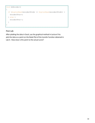
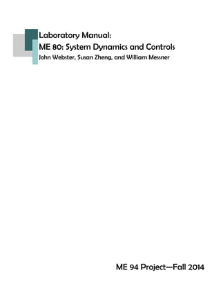
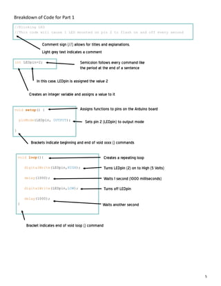
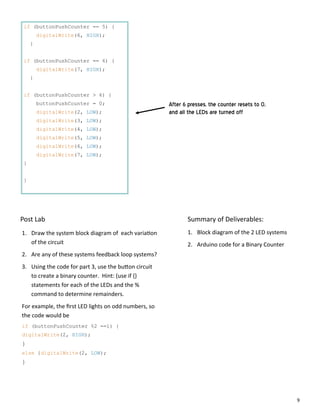
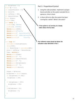
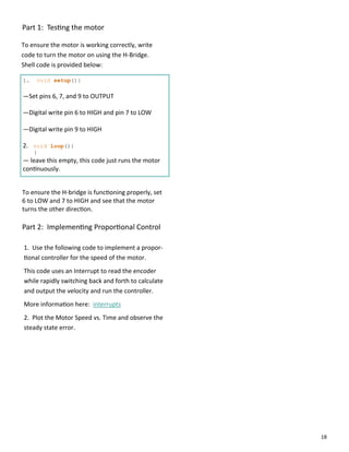
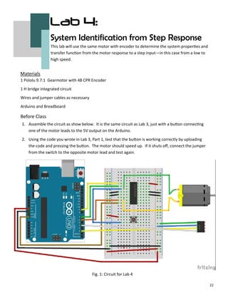
Part 1: System Parameters from Step Response
#define encoder0PinA 2
#define encoder0PinB 4
volatile long encoder0Pos = 0;
int newposition;
int oldposition = 0;
double newtime;
double oldtime = 0;
double vel;
const int numReadings = 11;
int readings[numReadings];
int index = 0;
int total = 0;
int average = 0;
The Pololu encoder does not read steady state speeds very accurately, as small varia ons in
ming intervals can cause large varia ons in motor output speed. To limit this effect, this
code employs a smoothing algorithm to calculate a floa ng average motor speed (based off
of 11 samples). This allows for smoother measurements while s ll maintaining enough res‐
olu on to observe the step response.
Part 1: Code
Code con nued on next page
Sets number of values in each
calculated average](https://image.slidesharecdn.com/098045b1-a61f-401c-93da-44b9d8bded07-150210202441-conversion-gate01/85/publish-manual-23-320.jpg)
![24
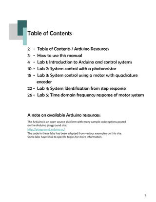
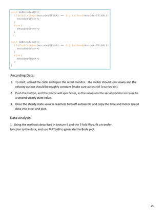
void setup() {
pinMode(9, OUTPUT);
pinMode(6, OUTPUT);
pinMode(7, OUTPUT);
Serial.begin(9600);
Serial.println(" ");
Serial.println(" ");
Serial.print("Time");
Serial.println(" Motor Speed");
attachInterrupt(0, doEncoderA, CHANGE);
attachInterrupt(1, doEncoderB, CHANGE);
digitalWrite(9, HIGH);
digitalWrite(6, LOW);
digitalWrite(7, HIGH);
for (int thisReading = 0; thisReading < numReadings; thisReading++)
readings[thisReading] = 0;
}
void loop() {
newtime=(.000001*micros());
if ((newtime-oldtime)>.00001){
newposition=encoder0Pos;
vel=abs((newposition-oldposition)/(newtime-oldtime));
total= total - readings[index];
readings[index] = vel;
total= total + readings[index];
index = index + 1;
if (index >= numReadings){
index = 0;
}
average = total / numReadings;
Serial.print(newtime);
Serial.print(" ");
Serial.println(average);
oldposition=newposition;
oldtime=newtime;
}
}
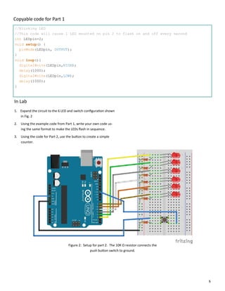
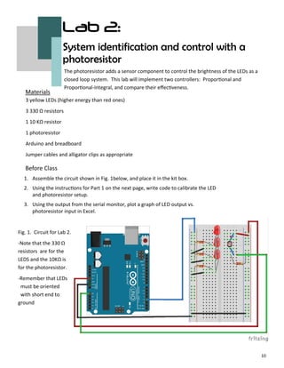
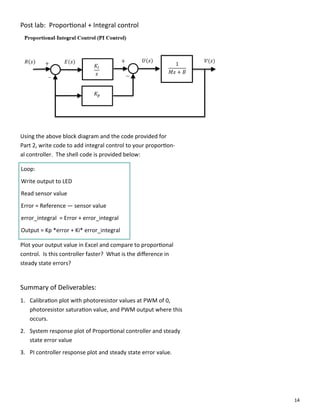
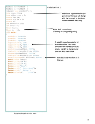
Attaches interrupts both A and B
encoders for higher resolution
Measures average
speed from the
measured motor
speeds and number
of readings
Code con nued on next page](https://image.slidesharecdn.com/098045b1-a61f-401c-93da-44b9d8bded07-150210202441-conversion-gate01/85/publish-manual-24-320.jpg)
![27
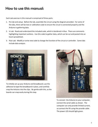
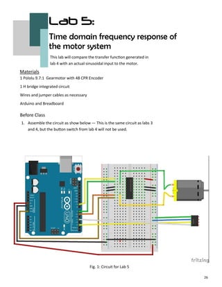
//Lab 5 frequency response
#define encoder0PinA 2
#define encoder0PinB 4
volatile long encoder0Pos=0;
long newposition;
long oldposition = 0;
double newtime;
double oldtime = 0;
long interval = 20;
long vel;
long Output;
int ledPin = 10;
float sinVal;
int ledVal;
const int numReadings = 10;
int readings[numReadings];
int index = 0;
int total = 0;
int average = 0;
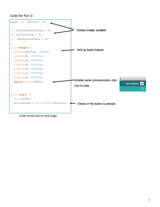
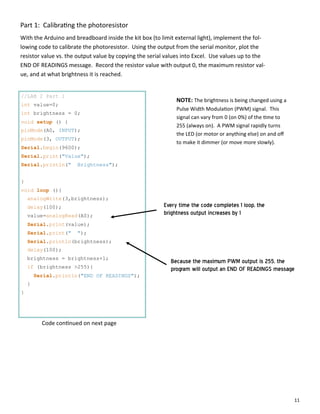
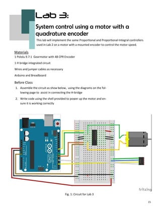
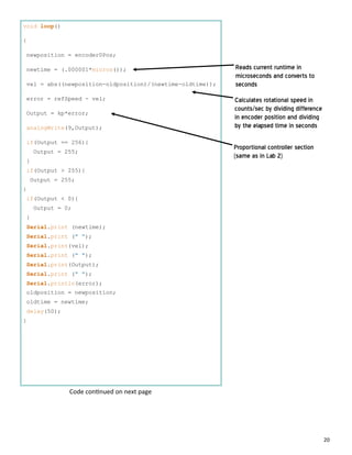
In Lab
Use the code provided to input a sinusoidal waveform into the motor and record the response.
Copy and paste the data into Excel to plot the Output and Motor Speed vs. Time. This data will be
compared with the transfer func on derived in Lab 4.
Code for Lab 5:
Code con nued on next page](https://image.slidesharecdn.com/098045b1-a61f-401c-93da-44b9d8bded07-150210202441-conversion-gate01/85/publish-manual-27-320.jpg)
![28
void setup(){
pinMode(9, OUTPUT);
pinMode(7, OUTPUT);
pinMode(6, OUTPUT);
digitalWrite(7, LOW);
digitalWrite(6, HIGH);
digitalWrite(9, HIGH);
pinMode(encoder0PinA, INPUT);
digitalWrite(encoder0PinA, HIGH);
pinMode(encoder0PinB, INPUT);
digitalWrite(encoder0PinB, HIGH);
attachInterrupt(0, doEncoder, RISING);
Serial.begin (9600);
Serial.println(" ");
Serial.println(" ");
Serial.print("Time");
Serial.print(" ");
Serial.print("Output");
Serial.print(" ");
Serial.println("MotorSpeed");
for (int thisReading = 0; thisReading < numReadings; thisReading++)
readings[thisReading] = 0;
}
Code con nued on next page](https://image.slidesharecdn.com/098045b1-a61f-401c-93da-44b9d8bded07-150210202441-conversion-gate01/85/publish-manual-28-320.jpg)
![29
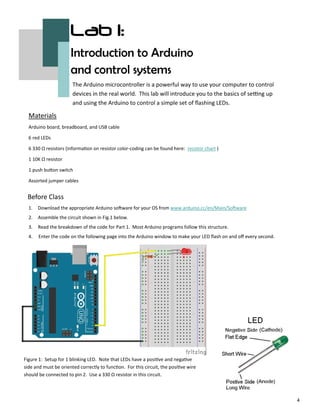
void loop(){
for (int x=0; x<360; x++) {
sinVal = (sin(radians(x)));
Output = int(sinVal*70+185);
delay(10);
analogWrite(9, Output);
newtime = (.000001*micros());
newposition = encoder0Pos;
vel = abs((newposition-oldposition)/(newtime-oldtime));
total= total - readings[index];
readings[index] = vel;
total= total + readings[index];
index = index + 1;
if (index >= numReadings)
index = 0;
average = total / numReadings;
Serial.print(newtime);
Serial.print(" ");
Serial.print(Output);
Serial.print(" ");
Serial.println(average);
}
if (newtime - oldtime > interval){
oldposition = newposition;
oldtime = newtime;
}
}
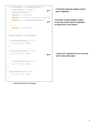
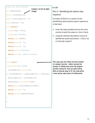
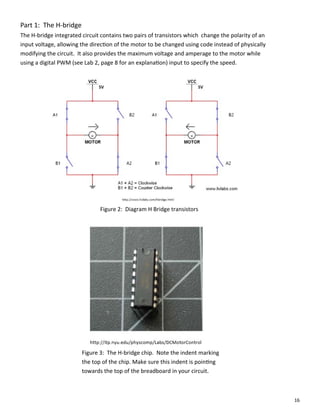
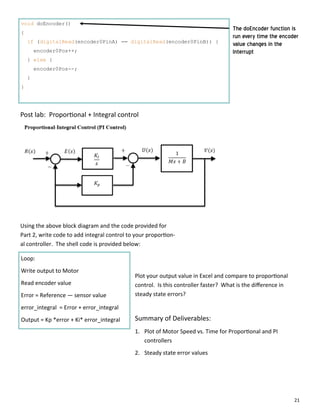
This For loop is the heart of this
lab exercise. It outputs a sine
wave varying from 115 (the
approximate output where the
motor will spin) and 255
(maximum motor speed)
NOTE: if your motor is stopping
at any point while the code is
running, shift the sine wave up by
adding a constant to the
sinVal*70+185 and subtracting half
of that value from 70
This exercise also incorporates the
smoothing algorithm to reduce
timing errors
Code con nued on next page](https://image.slidesharecdn.com/098045b1-a61f-401c-93da-44b9d8bded07-150210202441-conversion-gate01/85/publish-manual-29-320.jpg)