Download as PDF, PPTX


![Integer: used with integer variables with value between
2147483647 and -2147483647.
Ex: int x=1200;
Character: used with single character, represent value from -
127 to 128.
Ex. char c=‘r’;
Long: Long variables are extended size variables for number
storage, and store 32 bits (4 bytes), from -2,147,483,648 to
2,147,483,647.
Ex. long u=199203;
Floating-point numbers can be as large as 3.4028235E+38and
as low as -3.4028235E+38.They are stored as 32 bits (4 bytes) of
information.
Ex. float num=1.291; [The same as double type]
Data Types and operators](https://image.slidesharecdn.com/uctiottrainingpart3arduinoprogramming-200411174837/85/The-IoT-Academy-IoT-Training-Arduino-Part-3-programming-17-320.jpg)
![Statement represents a command, it ends with ;
Ex:
int x;
x=13;
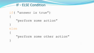
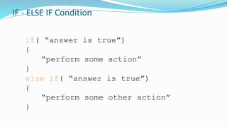
Operators are symbols that used to indicate a specific
function:
- Math operators: [+,-,*,/,%,^]
- Logic operators: [==, !=, &&, ||]
- Comparison operators: [==, >, <, !=, <=, >=]
Syntax:
; Semicolon, {} curly braces, //single line comment,
/*Multi-linecomments*/
Statement and operators:](https://image.slidesharecdn.com/uctiottrainingpart3arduinoprogramming-200411174837/85/The-IoT-Academy-IoT-Training-Arduino-Part-3-programming-18-320.jpg)
![Creating a bar graph using LEDs
const int NoLEDs = 8;
const int ledPins[] = { 70, 71, 72, 73, 74, 75, 76, 77};
const int analogInPin = 0; // Analog input pin const int wait = 30;
const boolean LED_ON = HIGH;
const boolean LED_OFF = LOW;
int sensorValue = 0; // value read from the sensor
int ledLevel = 0; // sensor value converted into LED 'bars'
void setup() {
for (int i = 0; i < NoLEDs; i++)
{
pinMode(ledPins[i], OUTPUT); // make all the LED pins outputs
}
}](https://image.slidesharecdn.com/uctiottrainingpart3arduinoprogramming-200411174837/85/The-IoT-Academy-IoT-Training-Arduino-Part-3-programming-47-320.jpg)
![Creating a bar graph using LEDs
void loop() {
sensorValue = analogRead(analogInPin); // read the analog in value
ledLevel = map(sensorValue, 0, 1023, 0, NoLEDs); // map to the number of LEDs
for (int i = 0; i < NoLEDs; i++)
{
if (i < ledLevel ) {
digitalWrite(ledPins[i], LED_ON); // turn on pins less than the level
}
else {
digitalWrite(ledPins[i], LED_OFF); // turn off pins higher than the level:
}
}
}](https://image.slidesharecdn.com/uctiottrainingpart3arduinoprogramming-200411174837/85/The-IoT-Academy-IoT-Training-Arduino-Part-3-programming-48-320.jpg)
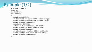
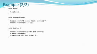


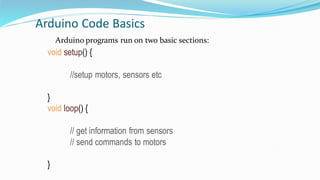
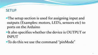
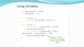
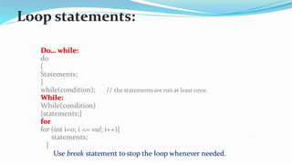
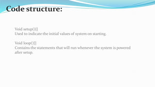
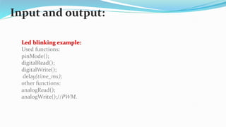
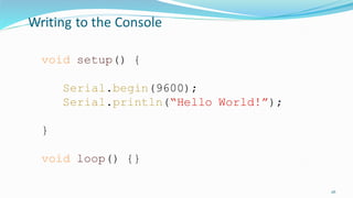
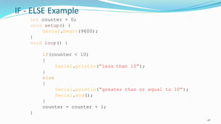
This document provides an overview of basic Arduino code structure and programming concepts. It explains that Arduino programs have two main sections - setup() and loop(). Setup() is used to initialize inputs and outputs, and loop() contains the repeating code. It also covers digital input/output functions, variables, conditional statements, boolean logic, and interrupts. Examples are provided for blinking LEDs, reading sensors, and creating simple programs.