Downloaded 228 times
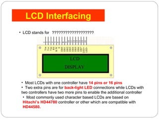
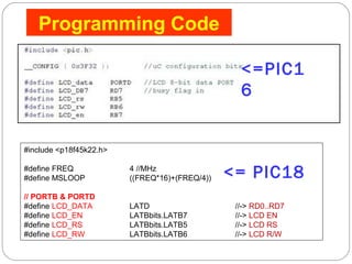
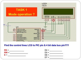
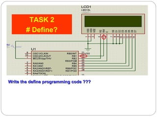
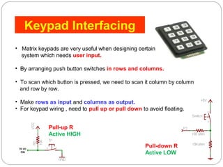
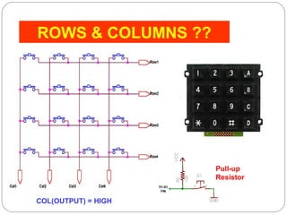
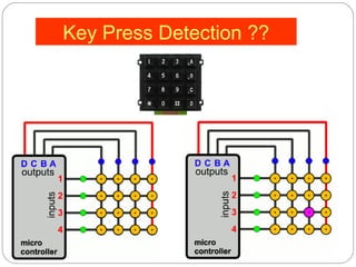
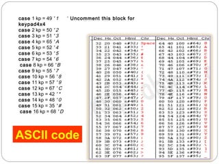
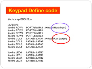
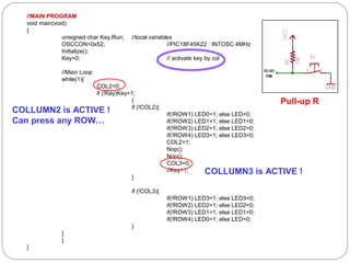
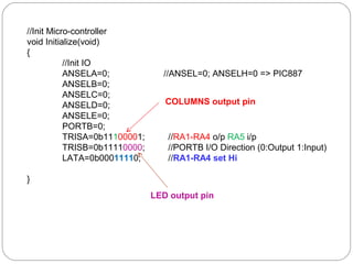
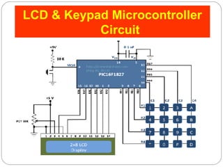

This document describes interfacing an LCD display and 4x4 keypad with a PIC microcontroller. It explains the basics of LCD operation including control lines and data bus. It also explains how a 4x4 matrix keypad works by scanning rows and columns to detect key presses. Programming code is provided to initialize the LCD and keypad interfaces as well as detect and identify keys pressed.


![SEQUENTIAL CIRCUITS [Flip-flops and Latches]](https://cdn.slidesharecdn.com/ss_thumbnails/sequentialcircuits-211217082412-thumbnail.jpg?width=640&height=640&fit=bounds)