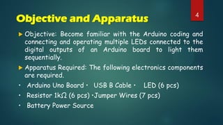
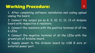
Project No:02
Title of Project: Blinking LEDs
Animation Connected To a Port
Presentation on Project
22Prepared For
Md. Alomgir Hossain
Senior Lecturer
Department of Computer Science & Engineering
Prepared By
Group – Micro Engineers Section-F
Name ID No Name ID No
Rihab Rahman (Leader) SECRET Abu Sufian Sabuj SECRET
Shohag Mia SECRET Mohammad Tamim Rahman SECRET
Alomgir Hossen SECRET Zerin Akter SECRET
Saifullah Al Mamun SECRET Kaisary Zaman SECRET
Tasnia Tahsin SECRET Maseat Nahar SECRET
Ikram Asif Khan Radi SECRET
Contents 3
 Objectives
 Apparatus Required
 Source Code
 Working Procedure
 Circuit And Schemetic Diagram
 Result
 Precautions
Objective and Apparatus
 Objective: Become familiar with the Arduino coding and
connecting and operating multiple LEDs connected to the
digital outputs of an Arduino board to light them
sequentially.
 Apparatus Required: The following electronics components
are required.
• Arduino Uno Board • USB B Cable • LED (6 pcs)
• Resistor 1kΩ (6 pcs) •Jumper Wires (7 pcs)
• Battery Power Source
4
5Source Code
int led = 13;
int led1 = 8;
int led2 = 9;
int led3 = 10;
int led4 = 11;
int led5 = 12;
int led6 = 13;
void setup()
{
pinMode(led1, OUTPUT);
pinMode(led2, OUTPUT);
pinMode(led3, OUTPUT);
pinMode(led4, OUTPUT);
pinMode(led5, OUTPUT);
pinMode(led6, OUTPUT);
}
6Source Code
void loop()
{
digitalWrite(led1, HIGH);
delay(200);
digitalWrite(led1, LOW);
delay(200);
digitalWrite(led2, HIGH);
delay(200);
digitalWrite(led2, LOW);
delay(200);
digitalWrite(led3, HIGH);
delay(200);
digitalWrite(led3, LOW);
delay(200);
digitalWrite(led4, HIGH);
delay(200);
digitalWrite(led4, LOW);
delay(200);
7Source Code
digitalWrite(led5, HIGH);
delay(200);
digitalWrite(led5, LOW);
delay(200);
digitalWrite(led6, HIGH);
delay(200);
digitalWrite(led6, LOW);
delay(200);
}
8Working Procedure:
1. After completing software installation and coding upload
unplug the board.
2. Connect the output pin no 8, 9, 10, 11, 12, 13 of Arduino
board with respective 6 resistors.
3. Connect the resistors with the positive terminal of all the
6 LEDs.
4. Connect the negative terminal of all the LEDs with the
ground pin of Arduino board.
5. Supply power to the Arduino board by USB B wire or
external power port.
9Circuit Diagram Schematic Diagram
10Result
 After making all the connections and uploading the code we found
that the connected LED lights are blinking sequentially as per the
coding.
Precaution:
 All the connections should be tight and proper.
 Handle the Arduino board carefully.
 Check the connection once again before powering the Arduino
board.
 Switch off the Arduino board after performing the Experiment.
Blinking LED's Animation Connected to a Port

Blinking LED's Animation Connected to a Port

  • 1.
    Project No:02 Title ofProject: Blinking LEDs Animation Connected To a Port Presentation on Project
  • 2.
    22Prepared For Md. AlomgirHossain Senior Lecturer Department of Computer Science & Engineering Prepared By Group – Micro Engineers Section-F Name ID No Name ID No Rihab Rahman (Leader) SECRET Abu Sufian Sabuj SECRET Shohag Mia SECRET Mohammad Tamim Rahman SECRET Alomgir Hossen SECRET Zerin Akter SECRET Saifullah Al Mamun SECRET Kaisary Zaman SECRET Tasnia Tahsin SECRET Maseat Nahar SECRET Ikram Asif Khan Radi SECRET
  • 3.
    Contents 3  Objectives Apparatus Required  Source Code  Working Procedure  Circuit And Schemetic Diagram  Result  Precautions
  • 4.
    Objective and Apparatus Objective: Become familiar with the Arduino coding and connecting and operating multiple LEDs connected to the digital outputs of an Arduino board to light them sequentially.  Apparatus Required: The following electronics components are required. • Arduino Uno Board • USB B Cable • LED (6 pcs) • Resistor 1kΩ (6 pcs) •Jumper Wires (7 pcs) • Battery Power Source 4
  • 5.
    5Source Code int led= 13; int led1 = 8; int led2 = 9; int led3 = 10; int led4 = 11; int led5 = 12; int led6 = 13; void setup() { pinMode(led1, OUTPUT); pinMode(led2, OUTPUT); pinMode(led3, OUTPUT); pinMode(led4, OUTPUT); pinMode(led5, OUTPUT); pinMode(led6, OUTPUT); }
  • 6.
    6Source Code void loop() { digitalWrite(led1,HIGH); delay(200); digitalWrite(led1, LOW); delay(200); digitalWrite(led2, HIGH); delay(200); digitalWrite(led2, LOW); delay(200); digitalWrite(led3, HIGH); delay(200); digitalWrite(led3, LOW); delay(200); digitalWrite(led4, HIGH); delay(200); digitalWrite(led4, LOW); delay(200);
  • 7.
    7Source Code digitalWrite(led5, HIGH); delay(200); digitalWrite(led5,LOW); delay(200); digitalWrite(led6, HIGH); delay(200); digitalWrite(led6, LOW); delay(200); }
  • 8.
    8Working Procedure: 1. Aftercompleting software installation and coding upload unplug the board. 2. Connect the output pin no 8, 9, 10, 11, 12, 13 of Arduino board with respective 6 resistors. 3. Connect the resistors with the positive terminal of all the 6 LEDs. 4. Connect the negative terminal of all the LEDs with the ground pin of Arduino board. 5. Supply power to the Arduino board by USB B wire or external power port.
  • 9.
  • 10.
    10Result  After makingall the connections and uploading the code we found that the connected LED lights are blinking sequentially as per the coding. Precaution:  All the connections should be tight and proper.  Handle the Arduino board carefully.  Check the connection once again before powering the Arduino board.  Switch off the Arduino board after performing the Experiment.