This document discusses electronic components and materials, focusing on resistors and capacitors. It provides information on:
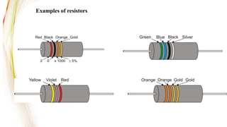
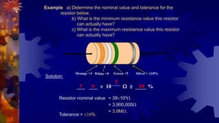
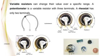
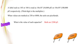
- The basic functions and types of resistors, including fixed resistors like carbon and metal film, as well as variable resistors. It describes how to read resistor color codes and calculate resistance values.
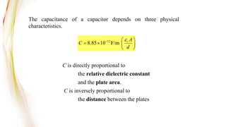
- The basic principle of how capacitors store and discharge electric charge based on capacitance, voltage, and dielectric material. It gives the equations for calculating capacitance and energy storage.
- Common capacitor types including mica, ceramic, electrolytic, and variable capacitors. It explains how capacitance depends on plate area, distance, and dielectric constant.