
Recommended
More Related Content
Similar to R C L Final presentation with main notes
Similar to R C L Final presentation with main notes (20)
Recently uploaded
Recently uploaded (20)
R C L Final presentation with main notes
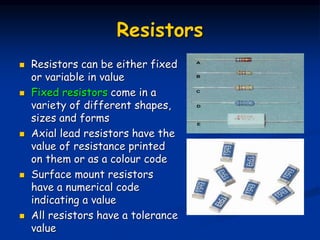
- 1. Resistors Resistors can be either fixed or variable in value Fixed resistors come in a variety of different shapes, sizes and forms Axial lead resistors have the value of resistance printed on them or as a colour code Surface mount resistors have a numerical code indicating a value All resistors have a tolerance value
- 2. Resistors Variable resistors are called potentiometers There is a fixed value of resistance between two terminals The moving part of the potentiometer is called the wiper
- 3. Resistors Four band resistor colour code 1st band provides the first digit of the code 2nd band provides the second digit of the code 3rd band is the multiplier 4th band indicates the tolerance value
- 5. Resistors Resistor colour code calculation The first band red has a value of 2 The second band purple has a value of 7 The third band has a multiplier of x 10 The last band indicates a tolerance value of +/-5% Resistance value is 270Ω +/-5% 2 7 x10 +/-5%
- 6. Capacitors A basic capacitor has two parallel plates separated by an insulating material A capacitor stores an electrical charge between the two plates The unit of capacitance is Farads (F) Capacitance values are normally smaller, such as µF, nF or pF
- 7. Capacitors Basic capacitor construction Dielectric material Plate 1 Plate 2 The dielectric material is an insulator therefore no current flows through the capacitor
- 8. Capacitors Storing a charge between the plates Electrons on the left plate are attracted toward the positive terminal of the voltage source This leaves an excess of positively charged holes The electrons are pushed toward the right plate Excess electrons leave a negative charge + - + _ + _
- 9. Capacitors Types of capacitors The dielectric material determines the type of capacitor Common types of capacitors are: Mica Ceramic Plastic film
- 10. Capacitors Some capacitors are polarised, they can only be connected one way around Electrolytic capacitors are polarised
- 11. Capacitors Variable capacitors are used in communication equipment, radios, televisions and VCRs They can be adjusted by consumers by tuning controls Trimmers are internal adjusted capacitors that a consumer cannot adjust
- 12. Capacitors These variable capacitors would be difficult to squeeze into your mobile phone and iPod Current technology uses semi-conductor variable capacitors called varactors (varicaps)
- 13. Capacitors The capacitance in a varactor is created when a purpose diode is reversed biased Adjusting the reverse bias alters the capacitance value A simple radio receiver using varactor http://www.microst.it
- 14. Capacitors Composed of two conductive plates separated by an insulator (or dielectric). Commonly illustrated as two parallel metal plates separated by a distance, d. C = e A/d where e = er eo er is the relative dielectric constant eo is the vacuum permittivity
- 15. Effect of Dimensions Capacitance increases with increasing surface area of the plates, decreasing spacing between plates, and increasing the relative dielectric constant of the insulator between the two plates.
- 16. Types of Capacitors Fixed Capacitors Nonpolarized May be connected into circuit with either terminal of capacitor connected to the high voltage side of the circuit. Insulator: Paper, Mica, Ceramic, Polymer Electrolytic The negative terminal must always be at a lower voltage than the positive terminal Plates or Electrodes: Aluminum, Tantalum
- 17. Nonpolarized Difficult to make nonpolarized capacitors that store a large amount of charge or operate at high voltages. Tolerance on capacitance values is very large +50%/-25% is not unusual http://www.marvac.com/fun/ceramic_capacitor_codes.a spx PSpice Symbol
- 19. Variable Capacitors Cross-sectional area is changed as one set of plates are rotated with respect to the other. http://www.tpub.com/neets/book2/3f.htm PSpice Symbol
- 20. Energy Storage Charge is stored on the plates of the capacitor. Equation: Q = CV Units: Farad = Coulomb/Voltage Farad is abbreviated as F
- 22. Ceq for Capacitors in Parallel i 4 3 2 1 eq 4 3 2 1 4 4 3 3 2 2 1 1 4 3 2 1 C C C C C dt dv C i dt dv C dt dv C dt dv C dt dv C i dt dv C i dt dv C i dt dv C i dt dv C i i i i i i eq in in in
- 24. Summary Capacitors are energy storage devices. An ideal capacitor act like an open circuit at steady state when a DC voltage or current has been applied. The voltage across a capacitor must be a continuous function; the current flowing through a capacitor can be discontinuous. The equations for equivalent capacitance for capacitors in parallel capacitors in series 1 1 1 S s s eq C C P p P eq C C 1 1 1 t t C C C C o dt i C v dt dv C i
- 25. Magnetic fields A magnetic field may be represented by a mathematical description of the magnetic influence of electric currents and magnetic materials. The magnetic field at any given point is specified by both a direction and a magnitude (or strength); as such it is a vector field Magnetic fields are produced by moving electric charges and the intrinsic magnetic moments of elementary particles Compasses reveal the direction of the local magnetic field. Magnetic field of an ideal cylindrical magnet with its axis of symmetry inside the image plane. Electromagnetism
- 26. Magnetic fields
- 27. Magnetic fields The magnetic flux is measured in webers (Wb) and the applied symbol is the capital Greek letter phi Φ Flux density
- 28. Inductors Inductors are coils of various dimensions designed to introduce specified amounts of inductance into a circuit. The inductance of a coil varies directly with the magnetic properties of the coil. Ferromagnetic materials, are frequently employed to increase the inductance by increasing the flux linking the coil. Inductance is measured in Henries (H) 1 Henry is the inductance level that will establish a voltage of 1 volt across the coil
- 29. Inductors An inductor is a passive two-terminal electrical component that stores energy in its magnetic field. An inductor is typically made of a wire or other conductor wound into a coil, to increase the magnetic field. When the current flowing through an inductor changes, creating a time-varying magnetic field inside the coil, a voltage is induced, according to Faraday's law of electromagnetic induction Inductors are one of the basic components used in electronics where current and voltage change with time, due to the ability of inductors to delay and reshape alternating currents.
- 31. FARADAY’S LAW OF ELECTROMAGNETIC INDUCTION If a conductor is moved through a magnetic field so that it cuts magnetic lines of flux, a voltage will be induced across the conductor The greater the number of flux lines cut per unit Time or the stronger the magnetic field strength, the greater will be the induced voltage across the conductor. Increase the number of magnetic flux lines by increasing the speed with which the conductor passes through the field Equation for voltage induced across a coil if a coil of N turns is placed in the region of a changing flux
- 32. Faraday’s law induced voltage equation If the flux linking the coil ceases to change = is the instantaneous change in flux (in webers) N = number of turns of the coil & Equation for inductance of the coils N = number of turns µ = permeability of the core A = area of the core in square meters l = the mean length of the core in meters. µ is not a constant but depends on the level of B and H, since µ = B/H
- 33. Substituting µ = µr µo into Equation we get Lo is the inductance of the coil with an air core