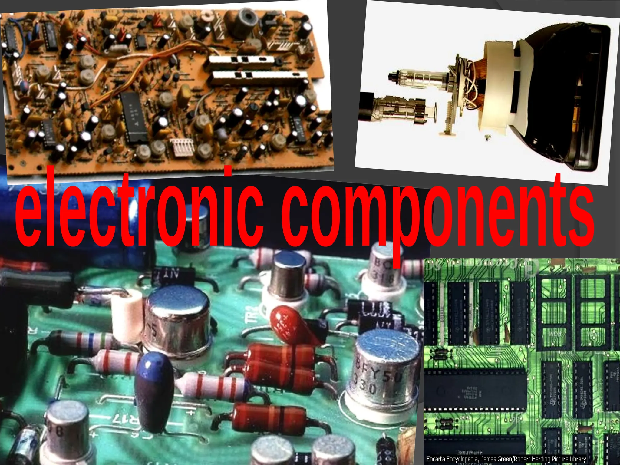
10-ELECTRONIC-COMPONENTS.components of electronicspptx
2.
RESISTANCE
The resistanceof your body to germs or
diseases is its power to remain
unharmed or unaffected by them.
Wind or air resistance is a force which
slows down a moving object or vehicle.
In electrical engineering or physics,
resistance is the ability of a substance or
an electrical circuit to stop the flow of an
electrical current through it.
RESISTOR
A RESISTOR isone of the most common components found in almost
any electrical and electronic equipment.
Resistors are circuit components that resist, control and limit the
amount of current and voltage, these components also produce
certain amounts of voltage drop.
A resistor is manufactured with specific value of ohms for its resistance
R. The purpose of using resistor in a circuit is either to reduce current I to a
specific value or to provide a desired voltage V.
CHARACTERISTICS OF RESISTORS
The two main characteristics of a resistor are its resistance R in ohms and its
power rating W in watts. Resistors are available in a wide range of R values, from a
fraction of an ohm to many thousands and millions of ohms.
Also important is the wattage rating, because it specifies the maximum power
the resistor can dissipate without excessive heat. Dissipation means that the
power is wasted, since the resultant heat is not used. Too much heat can
make the resistor burn. The wattage rating of the resistor is generally more than
the actual power dissipation, as a safety factor.
5.
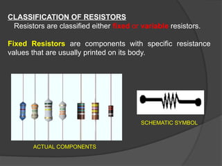
CLASSIFICATION OF RESISTORS
Resistorsare classified either fixed or variable resistors.
Fixed Resistors are components with specific resistance
values that are usually printed on its body.
SCHEMATIC SYMBOL
ACTUAL COMPONENTS
6.
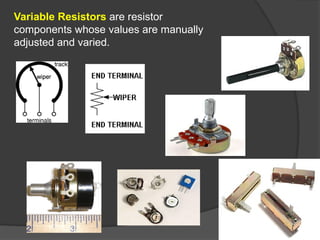
Variable Resistors areresistor
components whose values are manually
adjusted and varied.
7.
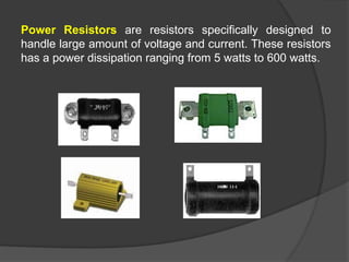
Power Resistors areresistors specifically designed to
handle large amount of voltage and current. These resistors
has a power dissipation ranging from 5 watts to 600 watts.
8.
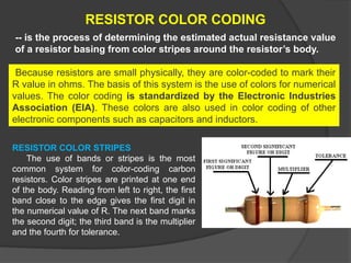
RESISTOR COLOR CODING
--is the process of determining the estimated actual resistance value
of a resistor basing from color stripes around the resistor’s body.
Because resistors are small physically, they are color-coded to mark their
R value in ohms. The basis of this system is the use of colors for numerical
values. The color coding is standardized by the Electronic Industries
Association (EIA). These colors are also used in color coding of other
electronic components such as capacitors and inductors.
RESISTOR COLOR STRIPES
The use of bands or stripes is the most
common system for color-coding carbon
resistors. Color stripes are printed at one end
of the body. Reading from left to right, the first
band close to the edge gives the first digit in
the numerical value of R. The next band marks
the second digit; the third band is the multiplier
and the fourth for tolerance.
9.
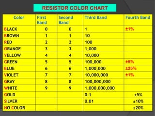
Color First
Band
Second
Band
Third BandFourth Band
BLACK 0 0 1 ±1%
BROWN 1 1 10
RED 2 2 100
ORANGE 3 3 1,000
YELLOW 4 4 10,000
GREEN 5 5 100,000 ±5%
BLUE 6 6 1,000,000 ±25%
VIOLET 7 7 10,000,000 ±1%
GRAY 8 8 100,000,000
WHITE 9 9 1,000,000,000
GOLD 0.1 ±5%
SILVER 0.01 ±10%
NO COLOR ±20%
RESISTOR COLOR CHART
10.
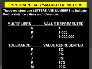
TYPOGRAPHICALYY-MARKED RESISTORS
These resistorsuse LETTERS AND NUMBERS to indicate
their resistance values and tolerances:
MULTIPLIERS VALUE REPRESENTED
R 1
K 1,000
J 1,000,000
TOLERANCE VALUE REPRESENTED
F 1%
G 2%
J 5%
K 10%
M 20%
11.
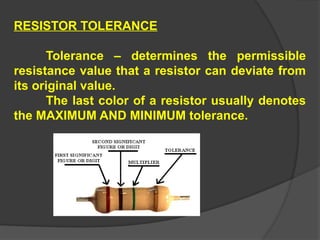
RESISTOR TOLERANCE
Tolerance –determines the permissible
resistance value that a resistor can deviate from
its original value.
The last color of a resistor usually denotes
the MAXIMUM AND MINIMUM tolerance.
12.
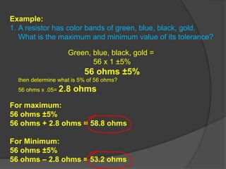
Example:
1. A resistorhas color bands of green, blue, black, gold.
What is the maximum and minimum value of its tolerance?
Green, blue, black, gold =
56 x 1 ±5%
56 ohms ±5%
then determine what is 5% of 56 ohms?
56 ohms x .05= 2.8 ohms
For maximum:
56 ohms ±5%
56 ohms + 2.8 ohms = 58.8 ohms
For Minimum:
56 ohms ±5%
56 ohms – 2.8 ohms = 53.2 ohms
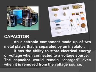
CAPACITOR
An electronic componentmade up of two
metal plates that is separated by an insulator.
It has the ability to store electrical energy
or voltage when connected to a voltage source.
The capacitor would remain “charged” even
when it is removed from the voltage source.
15.
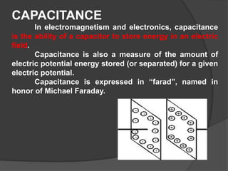
CAPACITANCE
In electromagnetism andelectronics, capacitance
is the ability of a capacitor to store energy in an electric
field.
Capacitance is also a measure of the amount of
electric potential energy stored (or separated) for a given
electric potential.
Capacitance is expressed in “farad”, named in
honor of Michael Faraday.
16.
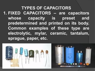
TYPES OF CAPACITORS
1.FIXED CAPACITORS – are capacitors
whose capacity is preset and
predetermined and printed on its body.
Common examples of these type are
electrolytic, mylar, ceramic, tantalum,
sprague, paper, etc.
17.
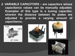
2. VARIABLE CAPACITORS– are capacitors whose
capacitance values can be manually adjusted.
Examples of this type is a tuning capacitor,
wherein the distance between its plates are
adjusted to provide a varying amount of
capacitance.
18.
Defective Capacitors
Defective capacitorscould no longer store charge and
in some cases, it could also cause the circuit to become
defective. Most common defects of capacitors are open,
shorted and leaky.
SHORTED CAPACITOR- when the two plates have very little
amount of resistance.
OPEN CAPACITOR-when the two plates have very high
resistance and voltage can no longer be stored.
LEAKY CAPACITOR- when there is a significant amount of
resistance between the plates that could cause the stored
voltage to leak from one plate to another
19.
HOW TO CHECKA CAPACITOR
To be able to check a capacitor, the component
must be removed from the circuit before it could be
checked with an ohmmeter. Using the ohmmeter in
checking capacitors only determines the presence of
CONTINUITY of the capacitor and to determine the
charging and discharging capability of the component.
1. Set the ohmmeter to Rx1 or Rx10 9or any appropriate
multiplier);
2. Be sure that there is no stored voltage on the capacitor by
means of discharging the stored capacitor present;
3. Slowly connect the test leads of the ohmmeter to the
terminals of the capacitor;
4. The meter should give a reading (needle will deflect) and
gradually the needle should return to infinite.
5. Reverse the polarity of the test leads and the reading
should give the same reading. This is the ideal test result.
20.
1.If the ohmmetergives a very low
resistance and the needle does not return
to infinite, the capacitor is SHORTED.
2.If the ohmmeter does not indicate any
resistance/deflection in any of the
ohmmeter multiplier, the capacitor could
be OPEN.
3.If the ohmmeter needle gives a resistance
reading but the needle do not return
completely to infinite, the capacitor could
be LEAKY.
DEFECTIVE TEST RESULTS
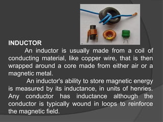
INDUCTOR
An inductor isusually made from a coil of
conducting material, like copper wire, that is then
wrapped around a core made from either air or a
magnetic metal.
An inductor's ability to store magnetic energy
is measured by its inductance, in units of henries.
Any conductor has inductance although the
conductor is typically wound in loops to reinforce
the magnetic field.
23.
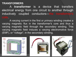
TRANSFORMERS
A transformer isa device that transfers
electrical energy from one circuit to another through
inductively coupled conductors—the transformer's
coils.
A varying current in the first or primary winding creates a
varying magnetic flux in the transformer's core and thus a
varying magnetic field through the secondary winding. This
varying magnetic field induces a varying electromotive force
(EMF), or "voltage", in the secondary winding.
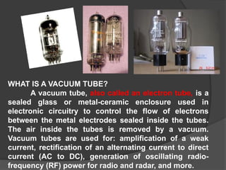
WHAT IS AVACUUM TUBE?
A vacuum tube, also called an electron tube, is a
sealed glass or metal-ceramic enclosure used in
electronic circuitry to control the flow of electrons
between the metal electrodes sealed inside the tubes.
The air inside the tubes is removed by a vacuum.
Vacuum tubes are used for: amplification of a weak
current, rectification of an alternating current to direct
current (AC to DC), generation of oscillating radio-
frequency (RF) power for radio and radar, and more.
26.
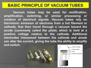
BASIC PRINCIPLE OFVACUUM TUBES
Vacuum tubes may be used for rectification,
amplification, switching, or similar processing or
creation of electrical signals. Vacuum tubes rely on
thermionic emission of electrons from a hot filament or
cathode, that then travel through a vacuum toward the
anode (commonly called the plate), which is held at a
positive voltage relative to the cathode. Additional
electrodes interposed between the cathode and anode
can alter the current, giving the tube the ability to amplify
and switch.
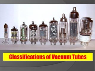
Types of VacuumTubes
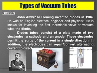
DIODES
John Ambrose Fleming invented diodes in 1904.
He was an English electrical engineer and physicist. He is
known for inventing the first thermionic valve or vacuum
tube, the diode.
Diodes tubes consist of a plate made of two
electrodes: a cathode and an anode. These electrodes
permit the surge of the current in a single direction. In
addition, the electrodes can repair/convert alternating
current to direct current.
29.
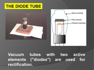
Vacuum tubes withtwo active
elements ("diodes") are used for
rectification.
THE DIODE TUBE
30.
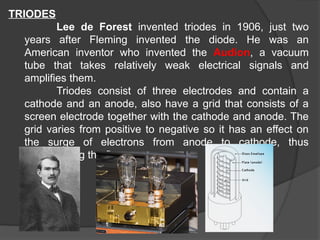
TRIODES
Lee de Forestinvented triodes in 1906, just two
years after Fleming invented the diode. He was an
American inventor who invented the Audion, a vacuum
tube that takes relatively weak electrical signals and
amplifies them.
Triodes consist of three electrodes and contain a
cathode and an anode, also have a grid that consists of a
screen electrode together with the cathode and anode. The
grid varies from positive to negative so it has an effect on
the surge of electrons from anode to cathode, thus
manipulating the flow.
31.
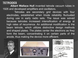
TETRODES
Albert Wallace Hullinvented tetrode vacuum tubes in
1926 and developed amplifiers and oscillators.
Tetrodes are secondary grid devices with four
electrodes, established when triode reliability fluctuated
during use in early radio sets. The issue was solved
because tetrodes increased intensification of energy at
high rates of recurrence. An additional modification is the
beam tetrode, which utilizes distinctive design methods
and shaped plates. The plates center the electrons as they
form the beam, concentrating it on certain parts of the
anode, thus making the device more efficient.
32.
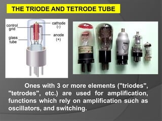
Ones with 3or more elements ("triodes",
"tetrodes", etc.) are used for amplification,
functions which rely on amplification such as
oscillators, and switching.
THE TRIODE AND TETRODE TUBE
33.
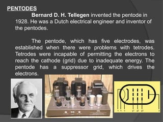
PENTODES
Bernard D. H.Tellegen invented the pentode in
1928. He was a Dutch electrical engineer and inventor of
the pentodes.
The pentode, which has five electrodes, was
established when there were problems with tetrodes.
Tetrodes were incapable of permitting the electrons to
reach the cathode (grid) due to inadequate energy. The
pentode has a suppressor grid, which drives the
electrons.
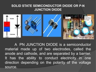
SOLID STATE SEMICONDUCTORDIODE OR P-N
JUNCTION DIODE
A PN JUNCTION DIODE is a semiconductor
material made up of two electrodes, called the
anode and cathode, and are separated by a barrier.
It has the ability to conduct electricity in one
direction depending on the polarity of the voltage
source.
36.
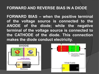
FORWARD AND REVERSEBIAS IN A DIODE
FORWARD BIAS – when the positive terminal
of the voltage source is connected to the
ANODE of the diode; while the negative
terminal of the voltage source is connected to
the CATHODE of the diode. This connection
makes the diode conduct electricity.
37.
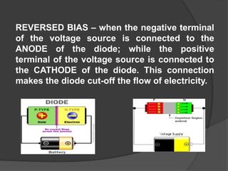
REVERSED BIAS –when the negative terminal
of the voltage source is connected to the
ANODE of the diode; while the positive
terminal of the voltage source is connected to
the CATHODE of the diode. This connection
makes the diode cut-off the flow of electricity.
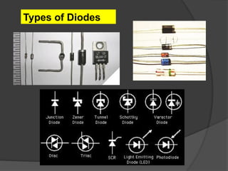
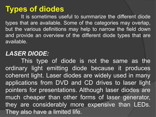
Types of diodes
Itis sometimes useful to summarize the different diode
types that are available. Some of the categories may overlap,
but the various definitions may help to narrow the field down
and provide an overview of the different diode types that are
available.
LASER DIODE:
This type of diode is not the same as the
ordinary light emitting diode because it produces
coherent light. Laser diodes are widely used in many
applications from DVD and CD drives to laser light
pointers for presentations. Although laser diodes are
much cheaper than other forms of laser generator,
they are considerably more expensive than LEDs.
They also have a limited life.
40.
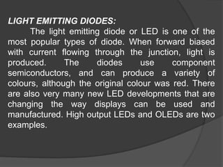
LIGHT EMITTING DIODES:
Thelight emitting diode or LED is one of the
most popular types of diode. When forward biased
with current flowing through the junction, light is
produced. The diodes use component
semiconductors, and can produce a variety of
colours, although the original colour was red. There
are also very many new LED developments that are
changing the way displays can be used and
manufactured. High output LEDs and OLEDs are two
examples.
41.
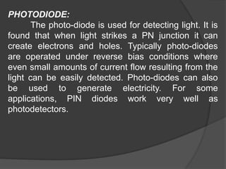
PHOTODIODE:
The photo-diode isused for detecting light. It is
found that when light strikes a PN junction it can
create electrons and holes. Typically photo-diodes
are operated under reverse bias conditions where
even small amounts of current flow resulting from the
light can be easily detected. Photo-diodes can also
be used to generate electricity. For some
applications, PIN diodes work very well as
photodetectors.
42.
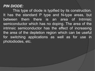
PIN DIODE:
This typeof diode is typified by its construction.
It has the standard P type and N-type areas, but
between them there is an area of Intrinsic
semiconductor which has no doping. The area of the
intrinsic semiconductor has the effect of increasing
the area of the depletion region which can be useful
for switching applications as well as for use in
photodiodes, etc.
43.
SCHOTTKY DIODES:
This typeof diode has a lower forward
voltage drop than ordinary silicon PN junction
diodes. At low currents the drop may be
somewhere between 0.15 and 0.4 volts as
opposed to 0.6 volts for a silicon diode. To achieve
this performance they are constructed in a different
way to normal diodes having a metal to
semiconductor contact. They are widely used as
clamping diodes, in RF applications, and also for
rectifier applications.
44.
PN JUNCTION:
The standardPN junction may be thought of
as the normal or standard type of diode in use
today. These diodes can come as small signal
types for use in radio frequency, or other low
current applications which may be termed as signal
diodes. Other types may be intended for high
current and high voltage applications and are
normally termed rectifier diodes.
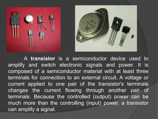
A transistor isa semiconductor device used to
amplify and switch electronic signals and power. It is
composed of a semiconductor material with at least three
terminals for connection to an external circuit. A voltage or
current applied to one pair of the transistor's terminals
changes the current flowing through another pair of
terminals. Because the controlled (output) power can be
much more than the controlling (input) power, a transistor
can amplify a signal.
51.
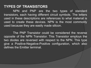
TYPES OF TRANSISTORS
NPNand PNP are the two types of standard
transistors, each having different circuit symbols. The letters
used in these descriptions are references to what material is
used to create these devices. NPN is the most commonly
used because they are easily made silicon.
The PNP Transistor could be considered the reverse
opposite of the NPN Transistor. This Transistor employs the
two diodes are reversed with respect to the NPN. This type
give a Positive-Negative-Positive configuration, which also
defines the Emitter terminal.
52.
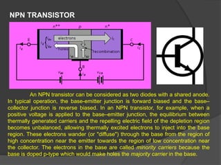
NPN TRANSISTOR
An NPNtransistor can be considered as two diodes with a shared anode.
In typical operation, the base-emitter junction is forward biased and the base–
collector junction is reverse biased. In an NPN transistor, for example, when a
positive voltage is applied to the base–emitter junction, the equilibrium between
thermally generated carriers and the repelling electric field of the depletion region
becomes unbalanced, allowing thermally excited electrons to inject into the base
region. These electrons wander (or "diffuse") through the base from the region of
high concentration near the emitter towards the region of low concentration near
the collector. The electrons in the base are called minority carriers because the
base is doped p-type which would make holes the majority carrier in the base.
53.
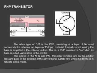
PNP TRANSISTOR
The othertype of BJT is the PNP, consisting of a layer of N-doped
semiconductor between two layers of P-doped material. A small current leaving the
base is amplified in the collector output. That is, a PNP transistor is "on" when its
base is pulled low relative to the emitter.
The arrows in the NPN and PNP transistor symbols are on the emitter
legs and point in the direction of the conventional current flow when the device is in
forward active mode.
54.
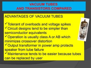
VACUUM TUBES
AND TRANSISTORSCOMPARED
ADVANTAGES OF VACUUM TUBES
Tolerant of overloads and voltage spikes
Circuit designs tend to be simpler than
semiconductor equivalents
Operation is usually class A or AB which
minimizes crossover distortion
Output transformer in power amp protects
speaker from tube failure
Maintenance tends to be easier because tubes
can be replaced by user
55.
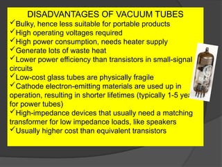
DISADVANTAGES OF VACUUMTUBES
Bulky, hence less suitable for portable products
High operating voltages required
High power consumption, needs heater supply
Generate lots of waste heat
Lower power efficiency than transistors in small-signal
circuits
Low-cost glass tubes are physically fragile
Cathode electron-emitting materials are used up in
operation, resulting in shorter lifetimes (typically 1-5 years
for power tubes)
High-impedance devices that usually need a matching
transformer for low impedance loads, like speakers
Usually higher cost than equivalent transistors
56.
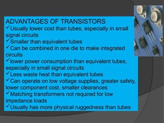
ADVANTAGES OF TRANSISTORS
Usuallylower cost than tubes, especially in small
signal circuits
Smaller than equivalent tubes
Can be combined in one die to make integrated
circuits
lower power consumption than equivalent tubes,
especially in small signal circuits
Less waste heat than equivalent tubes
Can operate on low voltage supplies, greater safety,
lower component cost, smaller clearances
Matching transformers not required for low
impedance loads
Usually has more physical ruggedness than tubes
57.
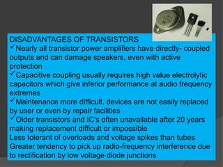
DISADVANTAGES OF TRANSISTORS
Nearlyall transistor power amplifiers have directly- coupled
outputs and can damage speakers, even with active
protection
Capacitive coupling usually requires high value electrolytic
capacitors which give inferior performance at audio frequency
extremes
Maintenance more difficult, devices are not easily replaced
by user or even by repair facilities
Older transistors and IC's often unavailable after 20 years
making replacement difficult or impossible
Less tolerant of overloads and voltage spikes than tubes
Greater tendency to pick up radio-frequency interference due
to rectification by low voltage diode junctions