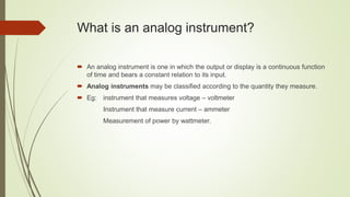
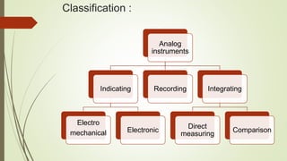
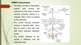
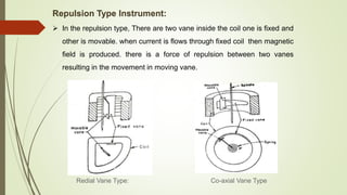
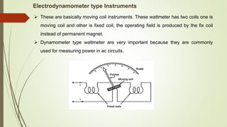
UNIT II
ANALOG INSTRUMENTS
Introduction to analog measuring instruments - Construction, principle and
applications of Moving coil instruments - Moving iron instruments -
Dynamometer type instrument - Induction type instrument - Statistical analysis
of error data (Simple problems) - Error correction methods - Instrument
transformer - Measurements of power using CT and PT.
What is an analog instrument?
 An analog instrument is one in which the output or display is a continuous function
of time and bears a constant relation to its input.
 Analog instruments may be classified according to the quantity they measure.
 Eg: instrument that measures voltage – voltmeter
Instrument that measure current – ammeter
Measurement of power by wattmeter.
Classification :
Analog
instruments
Indicating
Electro
mechanical Electronic
Recording Integrating
Direct
measuring
Comparison
Classification based on the effect
Magnetic effect
Thermal effect
Electrostatic effect
Electromagnetic effect
Hall effect
PMMC Instruments
 The instruments which use the permanent magnet for creating the stationary
magnetic field between which the coil moves is known as the permanent magnet
moving coil or PMMC instrument.
 It operates on the principle that the torque is exerted on the moving coil placed in the
field of the permanent magnet.
 The PMMC instrument gives the accurate result for DC measurement.
PMMC Instruments
 The Basic principle of Permanent
magnet type moving coil
instrument is that when a current
carrying conductor placed in a
magnetic field a force is exerted
on the conductor.
 The current carrying conductor
produce a magnetic field which
tries to come in line with main
field which produces deflection
torque.
 The pointer attached to the
spindle in deflection over the
calibrated scale.
Torque Equation for PMMC Instrument
The deflecting torque induces because of the movement of the coil. The
deflecting torque is expressed by the equation shown below.
Where,
N – Number of turns of coil
B – flux density in the air gap
L, d – the vertical and horizontal length of the side.
I – current through the coil.
The spring provides the restoring torque to the moving coil which is
expressed as
Where K = Spring constant.
For final deflection,
By substituting the value of equation
The above equation shows that the deflection torque is directly proportional
to the current passing through the coil.
Errors in Permanent Magnet Moving Coil
Instruments
(a) Errors due to permanent magnets.
(b) Error may appear in PMMC Instrument due to the aging of the spring.
(c) Change in the resistance of the moving coil with the temperature.
Advantages
1. Torque/weight is high
2. Power consumption is less
3. Scale is uniform
4. Damping is very effective
5. Since operating field is very strong, the effect of stray field is negligible
6. Range of instrument can be extended
Disadvantages
1. Use only for D.C.
2. Cost is high
3. Error is produced due to ageing effect of PMMC
4. Friction and temperature error are present
MI Instruments
Moving Iron Instruments are the most common type of ammeter and voltmeter used
at power frequencies in laboratories. These instruments are very accurate, cheap
and rugged as compared to other AC instruments.
Classification of Moving iron instruments:
 Attraction type
 Repulsion type
 The coil is flat and narrow slot like
opening.
 The moving iron is a flat disc and
made by nickel iron alloy
 When the current flows through the
coil, a magnetic field is produced and
the moving iron moves from the
weaker field outside the coil to the
stronger field inside it or in other
words the moving iron is attracted in.
 The controlling torque is provide by springs but gravity control can be
used for panel type of instruments which are vertically mounted.
 Damping is provided by air friction with the help of a light aluminium
piston (attached to the moving system) which move in a fixed chamber
closed at one end as shown in Fig. or with the help of a vane (attached
to the moving system) which moves in a fixed sector shaped chamber a
shown.
Attraction Type Instrument:
 In the repulsion type, There are two vane inside the coil one is fixed and
other is movable. when current is flows through fixed coil then magnetic
field is produced. there is a force of repulsion between two vanes
resulting in the movement in moving vane.
Repulsion Type Instrument:
Co-axial Vane Type
Redial Vane Type:
Torque equation of moving iron instruments can be draw by energy relation.
Where
Td = Deflection torque
θ = deflection and
L = coil inductance
Controlling Torque Tc is provided by controlling spring. Deflection torque is
balanced by
Controlling torque Tc = Kθ { Where K=Spring constant
Advantages
1. MI can be used in AC and DC
2. It is cheap
3. Supply is given to a fixed coil, not in moving coil.
4. Simple construction
5. Less friction error.
Disadvantages
1. It suffers from eddy current and hysteresis error
2. Scale is not uniform
3. It consumed more power
4. Calibration is different for AC and DC operation
Electrodynamometer type Instruments
 These are basically moving coil instruments. These wattmeter has two coils one is
moving coil and other is fixed coil, the operating field is produced by the fix coil
instead of permanent magnet.
 Dynamometer type wattmeter are very important because they are commonly
used for measuring power in ac circuits.
 The basic principle of Dynamometer type wattmeter is that when the
current carrying fixed coil produce magnetic field and current carrying
moving coil placed in magnetic field produce by fixed coil.
 A forced exerted on the moving coils sides and moving coil deflection
take place.
 Show the fig in which fixed coils are series coils connected with load in
series and carries the load current I1 .
 The moving coil is potential coil, it is connected parallel with load and
carries current I2 which is proportional to the load voltage when supply is
applied.
 Fixed coils produce the field Fm and Moving produce the field Fr.
 The field Fr tries to line with main field Fm , which produce the deflection
torque on the moving coil.
Electrodynamometer type Instruments
For D.C. operation :
For d.c current of I1 and I2,
The controlling torque is provided by springs hence
For A.C. operation :
Advantages:
1. Free from eddy current losses and hysteresis errors.
2. Used on both a.c. and d.c. They are also used as a transfer
instruments.
3. Provide accurate r.m.s values of voltage, irrespective of waveforms,
are required.
4. Low power Consumption.
5. Light in weight.
Disadvantages:
1. Low sensitivity due to a low torque to weight ratio.
2. Increased frictional losses.
3. More expensive than other type of instruments.
4. Non-uniform scale.
5. The operation current of these instruments is large due to the fact that
they have weak magnetic field.
 The meter which is used for measuring the energy utilizes by the electric load
is known as the energy meter.
Single Phase Induction Type Energy Meter
Other Representations:
 The energy is the total power consumed and utilized by the load at a
particular interval of time.
 It is used in domestic and industrial AC circuit for measuring the power
consumption. The meter is less expensive and accurate.
 The energy meter has four main parts. They are the
1. Driving System
2. Registering System
3. Moving System
4. Braking System
Driving System
 The electromagnet is the main component of the driving system.
 It is the temporary magnet which is excited by the current flow through
their coil.
 The core of the electromagnet is made up of silicon steel lamination.
 The driving system has two electromagnets. The upper one is called
the shunt electromagnet, and the lower one is called series
electromagnet.
Registration (Counting Mechanism)
 The main function of the registration or counting mechanism is to
record the number of rotations of the aluminium disc.
 Their rotation is directly proportional to the energy consumed by the
loads in the kilowatt hour.
Moving System
 The moving system is the aluminium disc mounted on the shaft of the
alloy.
 The disc is placed in the air gap of the two electromagnets.
 The eddy current is induced in the disc because of the change of the
magnetic field. This eddy current is cut by the magnetic flux.
 The interaction of the flux and the disc induces the deflecting torque.
Braking System
 The permanent magnet is used for reducing the rotation of the
aluminium disc.
 The aluminium disc induces the eddy current because of their rotation.
 The eddy current cut the magnetic flux of the permanent magnet and
hence produces the braking torque.
Instrument Transformer
• Instrument Transformers are used in AC system for measurement of electrical
quantities i.e. voltage, current, power, energy, power factor, frequency.
• Instrument transformers are also used with protective relays for protection of
power system.
• Basic function of Instrument transformers is to step down the AC System voltage
and current.
• Generally measuring instruments are designed for 5 A and 110 V.
• The current and voltage transformers are together called as the Instrument
transformers.
Current transformer:
• It is used for the measurement of the alternating current by taking
samples of the higher currents of the system. These reduced samples
are in accurate proportions with the actual high currents of the system.
Potential transformer:
It is quite similar to the current transformer, but it is used for taking
samples of high voltages of a system for providing low-voltage to the
relays of protection system and also to the low-rating meters for voltage
measurement.
Advantages:
1. The large voltage and current of AC Power system can be measured by
using small rating measuring instrument i.e. 5 A, 110 – 120 V.
2. By using the instrument transformers, measuring instruments can be
standardized.
3. Instrument transformers provide electrical isolation between high
voltage power circuit and measuring instruments.
4. Several measuring instruments can be connected through a single
transformer to power system.
5. Due to low voltage and current level in measuring and protective circuit,
there is low power consumption in measuring and protective circuits.
Solved Problems
S. No. Topic/Title Details of Resources
1 PMMC instruments https://www.youtube.com/watch?v=ZtBKC6WSjD0
2 MI Instruments https://www.youtube.com/watch?v=L9wHaLyv94Q
3 Electrodynamo meter https://www.youtube.com/watch?v=pyuVITDT0sE&t=32s
4 Instrument transformer
https://www.youtube.com/watch?v=CB0xyL5PHHI
https://www.youtube.com/watch?v=U3CubKnkO4c
5 1Φ induction type energy meter https://www.youtube.com/watch?v=mQmckFPo5_c
Animations:

UNIT 2.pptx

  • 1.
    UNIT II ANALOG INSTRUMENTS Introductionto analog measuring instruments - Construction, principle and applications of Moving coil instruments - Moving iron instruments - Dynamometer type instrument - Induction type instrument - Statistical analysis of error data (Simple problems) - Error correction methods - Instrument transformer - Measurements of power using CT and PT.
  • 2.
    What is ananalog instrument?  An analog instrument is one in which the output or display is a continuous function of time and bears a constant relation to its input.  Analog instruments may be classified according to the quantity they measure.  Eg: instrument that measures voltage – voltmeter Instrument that measure current – ammeter Measurement of power by wattmeter.
  • 3.
  • 4.
    Classification based onthe effect Magnetic effect Thermal effect Electrostatic effect Electromagnetic effect Hall effect
  • 5.
    PMMC Instruments  Theinstruments which use the permanent magnet for creating the stationary magnetic field between which the coil moves is known as the permanent magnet moving coil or PMMC instrument.  It operates on the principle that the torque is exerted on the moving coil placed in the field of the permanent magnet.  The PMMC instrument gives the accurate result for DC measurement.
  • 6.
    PMMC Instruments  TheBasic principle of Permanent magnet type moving coil instrument is that when a current carrying conductor placed in a magnetic field a force is exerted on the conductor.  The current carrying conductor produce a magnetic field which tries to come in line with main field which produces deflection torque.  The pointer attached to the spindle in deflection over the calibrated scale.
  • 7.
    Torque Equation forPMMC Instrument The deflecting torque induces because of the movement of the coil. The deflecting torque is expressed by the equation shown below. Where, N – Number of turns of coil B – flux density in the air gap L, d – the vertical and horizontal length of the side. I – current through the coil. The spring provides the restoring torque to the moving coil which is expressed as
  • 8.
    Where K =Spring constant. For final deflection, By substituting the value of equation The above equation shows that the deflection torque is directly proportional to the current passing through the coil.
  • 9.
    Errors in PermanentMagnet Moving Coil Instruments (a) Errors due to permanent magnets. (b) Error may appear in PMMC Instrument due to the aging of the spring. (c) Change in the resistance of the moving coil with the temperature.
  • 10.
    Advantages 1. Torque/weight ishigh 2. Power consumption is less 3. Scale is uniform 4. Damping is very effective 5. Since operating field is very strong, the effect of stray field is negligible 6. Range of instrument can be extended Disadvantages 1. Use only for D.C. 2. Cost is high 3. Error is produced due to ageing effect of PMMC 4. Friction and temperature error are present
  • 11.
    MI Instruments Moving IronInstruments are the most common type of ammeter and voltmeter used at power frequencies in laboratories. These instruments are very accurate, cheap and rugged as compared to other AC instruments. Classification of Moving iron instruments:  Attraction type  Repulsion type
  • 12.
     The coilis flat and narrow slot like opening.  The moving iron is a flat disc and made by nickel iron alloy  When the current flows through the coil, a magnetic field is produced and the moving iron moves from the weaker field outside the coil to the stronger field inside it or in other words the moving iron is attracted in.  The controlling torque is provide by springs but gravity control can be used for panel type of instruments which are vertically mounted.  Damping is provided by air friction with the help of a light aluminium piston (attached to the moving system) which move in a fixed chamber closed at one end as shown in Fig. or with the help of a vane (attached to the moving system) which moves in a fixed sector shaped chamber a shown. Attraction Type Instrument:
  • 13.
     In therepulsion type, There are two vane inside the coil one is fixed and other is movable. when current is flows through fixed coil then magnetic field is produced. there is a force of repulsion between two vanes resulting in the movement in moving vane. Repulsion Type Instrument: Co-axial Vane Type Redial Vane Type:
  • 14.
    Torque equation ofmoving iron instruments can be draw by energy relation. Where Td = Deflection torque θ = deflection and L = coil inductance Controlling Torque Tc is provided by controlling spring. Deflection torque is balanced by Controlling torque Tc = Kθ { Where K=Spring constant
  • 15.
    Advantages 1. MI canbe used in AC and DC 2. It is cheap 3. Supply is given to a fixed coil, not in moving coil. 4. Simple construction 5. Less friction error. Disadvantages 1. It suffers from eddy current and hysteresis error 2. Scale is not uniform 3. It consumed more power 4. Calibration is different for AC and DC operation
  • 16.
    Electrodynamometer type Instruments These are basically moving coil instruments. These wattmeter has two coils one is moving coil and other is fixed coil, the operating field is produced by the fix coil instead of permanent magnet.  Dynamometer type wattmeter are very important because they are commonly used for measuring power in ac circuits.
  • 17.
     The basicprinciple of Dynamometer type wattmeter is that when the current carrying fixed coil produce magnetic field and current carrying moving coil placed in magnetic field produce by fixed coil.  A forced exerted on the moving coils sides and moving coil deflection take place.  Show the fig in which fixed coils are series coils connected with load in series and carries the load current I1 .  The moving coil is potential coil, it is connected parallel with load and carries current I2 which is proportional to the load voltage when supply is applied.  Fixed coils produce the field Fm and Moving produce the field Fr.  The field Fr tries to line with main field Fm , which produce the deflection torque on the moving coil.
  • 18.
    Electrodynamometer type Instruments ForD.C. operation : For d.c current of I1 and I2, The controlling torque is provided by springs hence For A.C. operation :
  • 19.
    Advantages: 1. Free fromeddy current losses and hysteresis errors. 2. Used on both a.c. and d.c. They are also used as a transfer instruments. 3. Provide accurate r.m.s values of voltage, irrespective of waveforms, are required. 4. Low power Consumption. 5. Light in weight. Disadvantages: 1. Low sensitivity due to a low torque to weight ratio. 2. Increased frictional losses. 3. More expensive than other type of instruments. 4. Non-uniform scale. 5. The operation current of these instruments is large due to the fact that they have weak magnetic field.
  • 20.
     The meterwhich is used for measuring the energy utilizes by the electric load is known as the energy meter. Single Phase Induction Type Energy Meter
  • 21.
  • 22.
     The energyis the total power consumed and utilized by the load at a particular interval of time.  It is used in domestic and industrial AC circuit for measuring the power consumption. The meter is less expensive and accurate.  The energy meter has four main parts. They are the 1. Driving System 2. Registering System 3. Moving System 4. Braking System
  • 23.
    Driving System  Theelectromagnet is the main component of the driving system.  It is the temporary magnet which is excited by the current flow through their coil.  The core of the electromagnet is made up of silicon steel lamination.  The driving system has two electromagnets. The upper one is called the shunt electromagnet, and the lower one is called series electromagnet. Registration (Counting Mechanism)  The main function of the registration or counting mechanism is to record the number of rotations of the aluminium disc.  Their rotation is directly proportional to the energy consumed by the loads in the kilowatt hour.
  • 24.
    Moving System  Themoving system is the aluminium disc mounted on the shaft of the alloy.  The disc is placed in the air gap of the two electromagnets.  The eddy current is induced in the disc because of the change of the magnetic field. This eddy current is cut by the magnetic flux.  The interaction of the flux and the disc induces the deflecting torque. Braking System  The permanent magnet is used for reducing the rotation of the aluminium disc.  The aluminium disc induces the eddy current because of their rotation.  The eddy current cut the magnetic flux of the permanent magnet and hence produces the braking torque.
  • 25.
    Instrument Transformer • InstrumentTransformers are used in AC system for measurement of electrical quantities i.e. voltage, current, power, energy, power factor, frequency. • Instrument transformers are also used with protective relays for protection of power system. • Basic function of Instrument transformers is to step down the AC System voltage and current. • Generally measuring instruments are designed for 5 A and 110 V. • The current and voltage transformers are together called as the Instrument transformers.
  • 26.
    Current transformer: • Itis used for the measurement of the alternating current by taking samples of the higher currents of the system. These reduced samples are in accurate proportions with the actual high currents of the system.
  • 27.
    Potential transformer: It isquite similar to the current transformer, but it is used for taking samples of high voltages of a system for providing low-voltage to the relays of protection system and also to the low-rating meters for voltage measurement.
  • 29.
    Advantages: 1. The largevoltage and current of AC Power system can be measured by using small rating measuring instrument i.e. 5 A, 110 – 120 V. 2. By using the instrument transformers, measuring instruments can be standardized. 3. Instrument transformers provide electrical isolation between high voltage power circuit and measuring instruments. 4. Several measuring instruments can be connected through a single transformer to power system. 5. Due to low voltage and current level in measuring and protective circuit, there is low power consumption in measuring and protective circuits.
  • 30.
  • 32.
    S. No. Topic/TitleDetails of Resources 1 PMMC instruments https://www.youtube.com/watch?v=ZtBKC6WSjD0 2 MI Instruments https://www.youtube.com/watch?v=L9wHaLyv94Q 3 Electrodynamo meter https://www.youtube.com/watch?v=pyuVITDT0sE&t=32s 4 Instrument transformer https://www.youtube.com/watch?v=CB0xyL5PHHI https://www.youtube.com/watch?v=U3CubKnkO4c 5 1Φ induction type energy meter https://www.youtube.com/watch?v=mQmckFPo5_c Animations: