This document explains the function and principles of various electrical measuring instruments, including ammeters, voltmeters, wattmeters, and power factor meters. It describes how each device measures current, voltage, power, and power factor with examples, classifications of types, and the underlying principles of their operation. Additionally, it presents numerical examples to illustrate calculations related to power measurement.

![Solution
Given: I3 = 2.5 A; I2 = 2.4 A; I1 = 4.5 A; V = 250 V.
Non-inductive resistance, R = (V/I2) = 250/2.4 = 104.17
i) Power absorbed by the load, P:
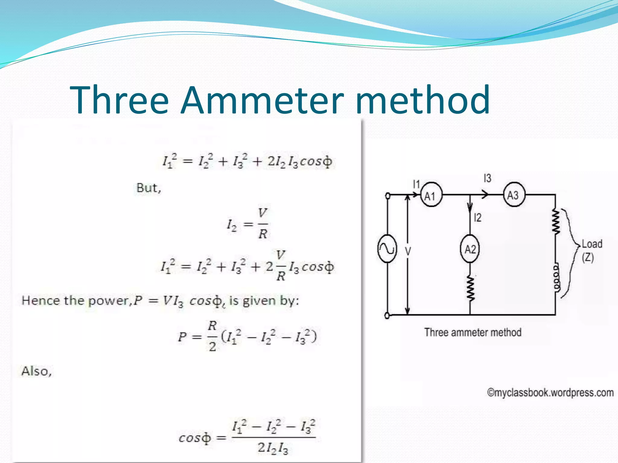
P = (R/2)*(I1^2 – I2^2 – I3^2)
= (104.17/2)((4.5^2)-(2.4^2)-(2.5^2)) = 429.2 W
ii) Load impedance, Z:
Z = (V/I3) = (250/2.5) = 100
iii) Power factor of the load, cos ? = (I1^2 – I2^2
– I3^2) /2I2I3
= [(4.5^2)-(2.4^2)-(2.5^2)]/(2*2.4*2.5) = 0.687 (Ans.)](https://image.slidesharecdn.com/ammetervoltmeterwattmeterpowerfactormeter-200615101716/75/Ammeter-voltmeter-wattmeter-power-factor-meter-8-2048.jpg)

![Numerical Example:
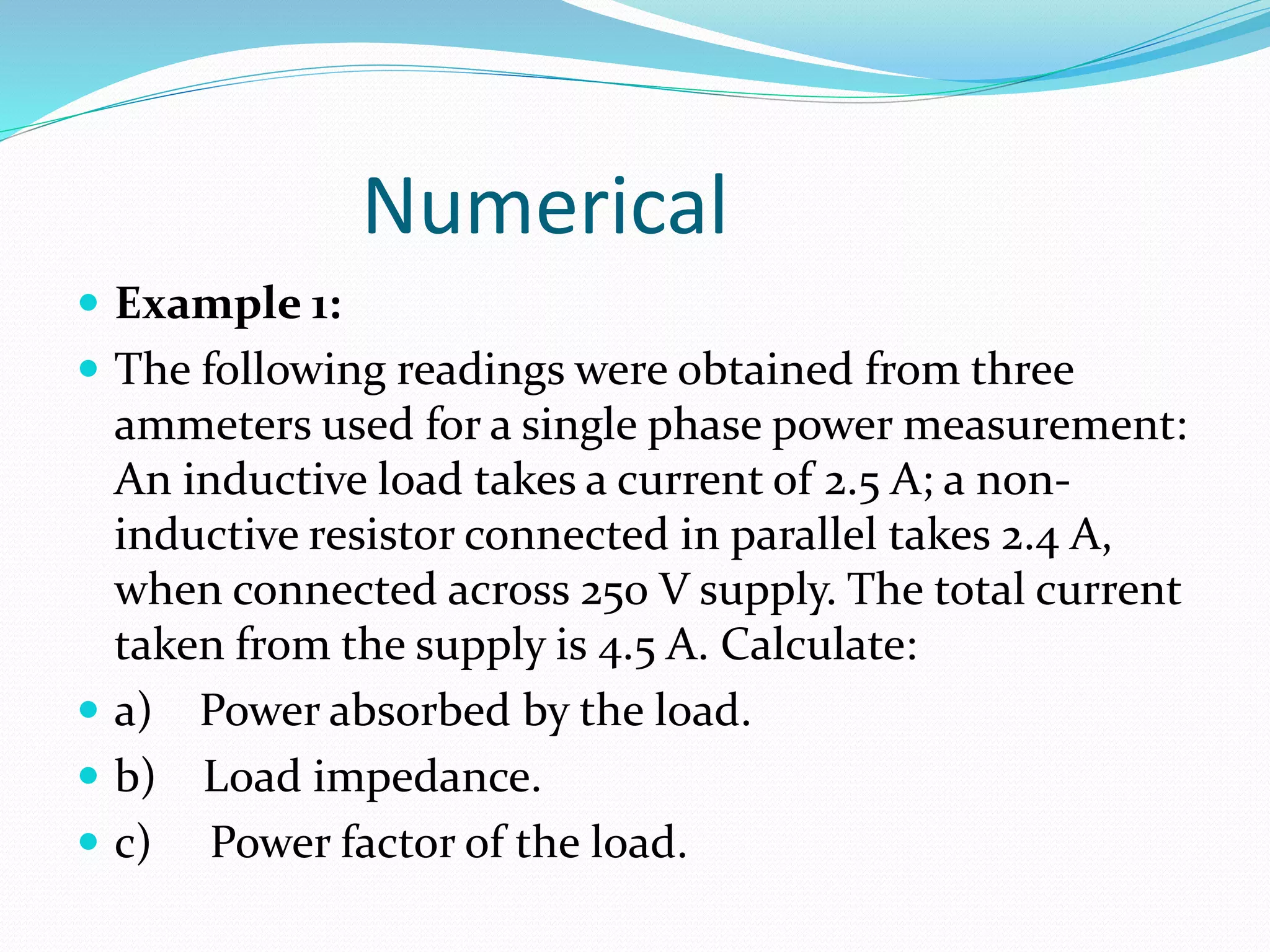
Example 1:
The following readings were obtained from three
voltmeters used for a single phase power measurement:
V2 = 180 voltas across a non-inductive resistaor; V3 = 200
volts across an inductive load; V1 = 300 volts across the two
in series.
Calculate the power factor of the inductive load.
Solution:
Given: V2 = 180 V; V3 = 200 V; V1 = 300 V
Power factor, cos ? = (V1^2 – V2^2 – V3^3)/2V2V3
Or cos ? = [(300^2) – (180^2) – (200^2)]/(2*180*200) =
0.244 (Ans.)](https://image.slidesharecdn.com/ammetervoltmeterwattmeterpowerfactormeter-200615101716/75/Ammeter-voltmeter-wattmeter-power-factor-meter-14-2048.jpg)


![potentiometer presentation slide [Autosaved].pptx](https://cdn.slidesharecdn.com/ss_thumbnails/potentiometerpresentationslideautosaved-240204142748-a5b488e5-thumbnail.jpg?width=640&height=640&fit=bounds)
![ELECTRICAL MEASUREMENT & MEASURING INSTRUMENTS [Emmi- (NEE-302) -unit-1]](https://cdn.slidesharecdn.com/ss_thumbnails/emmi-nee-302-unit-1-170607090405-thumbnail.jpg?width=640&height=640&fit=bounds)