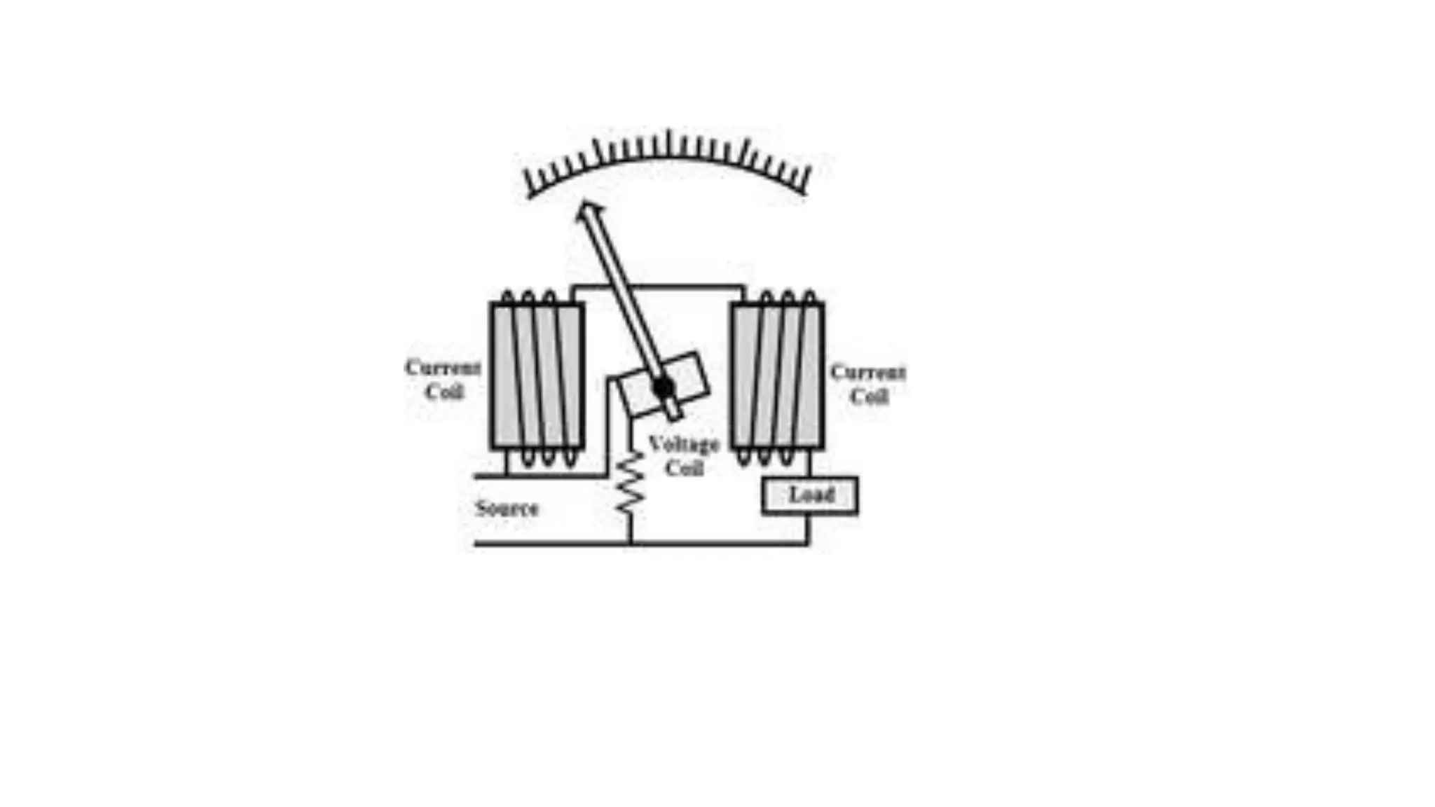
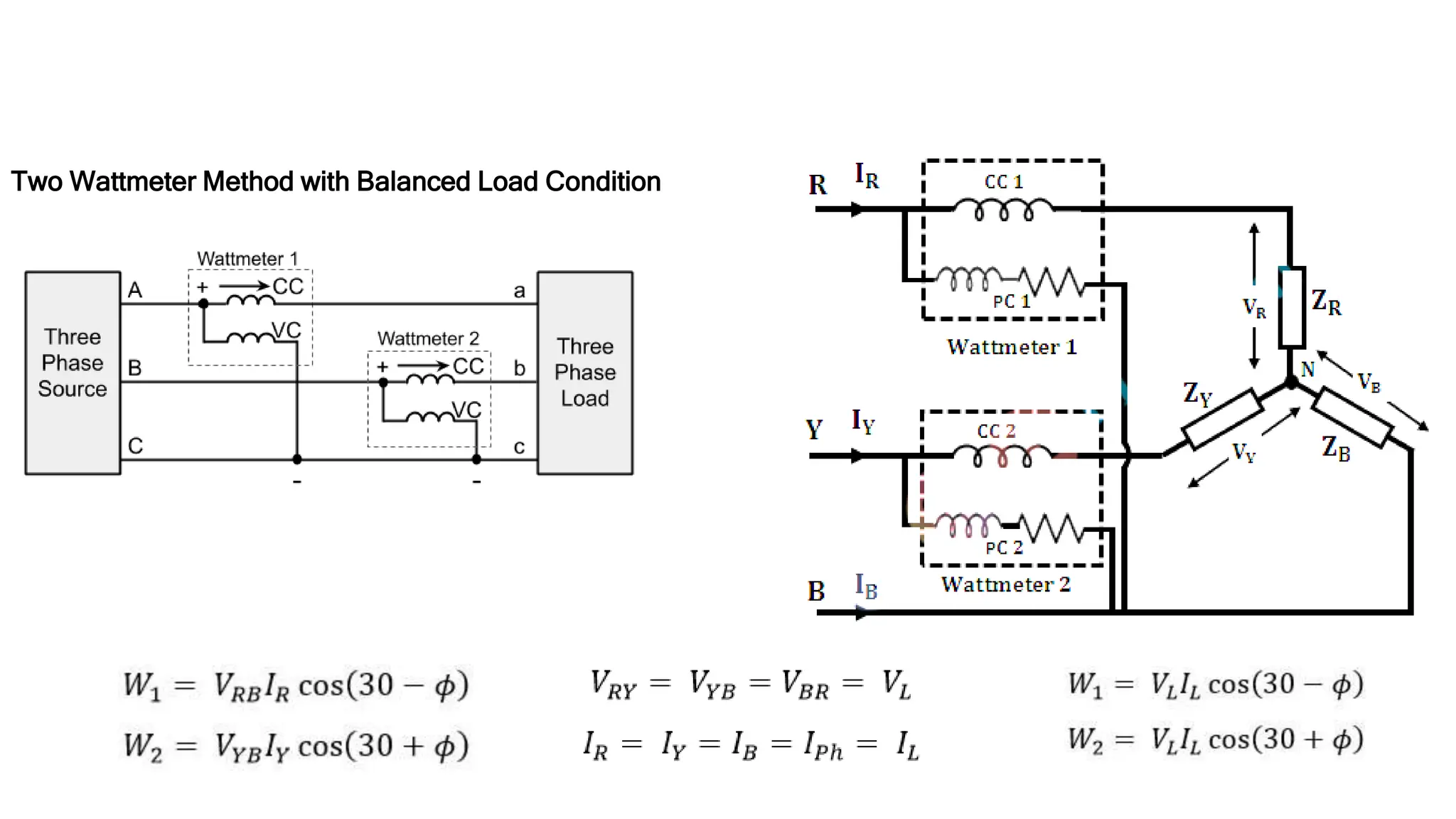
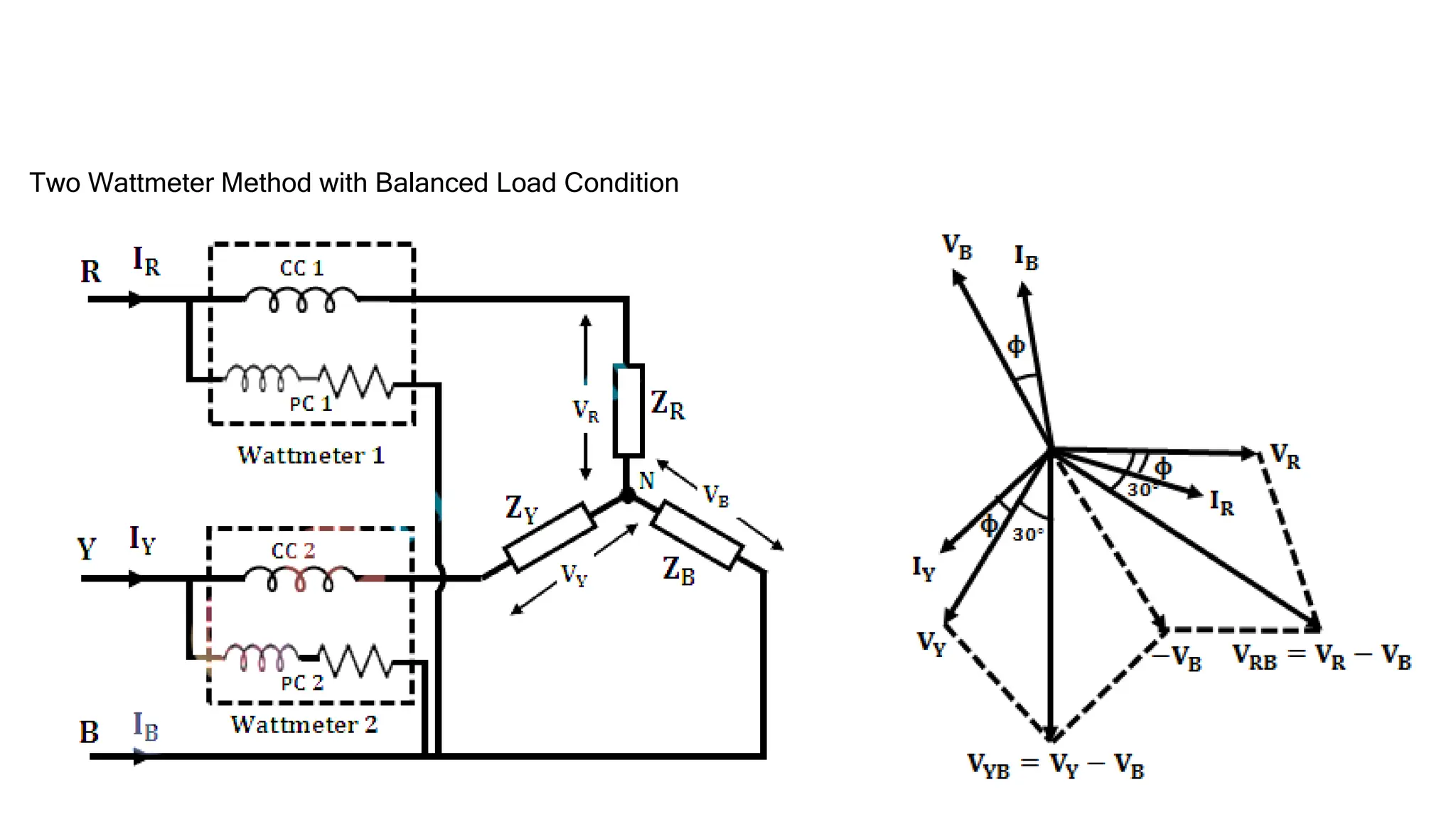
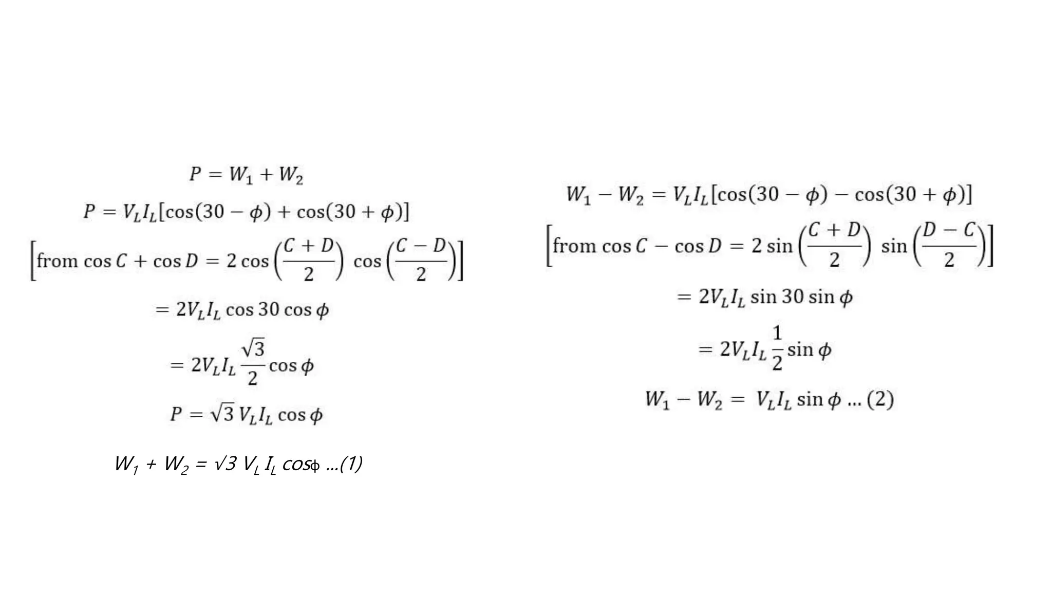
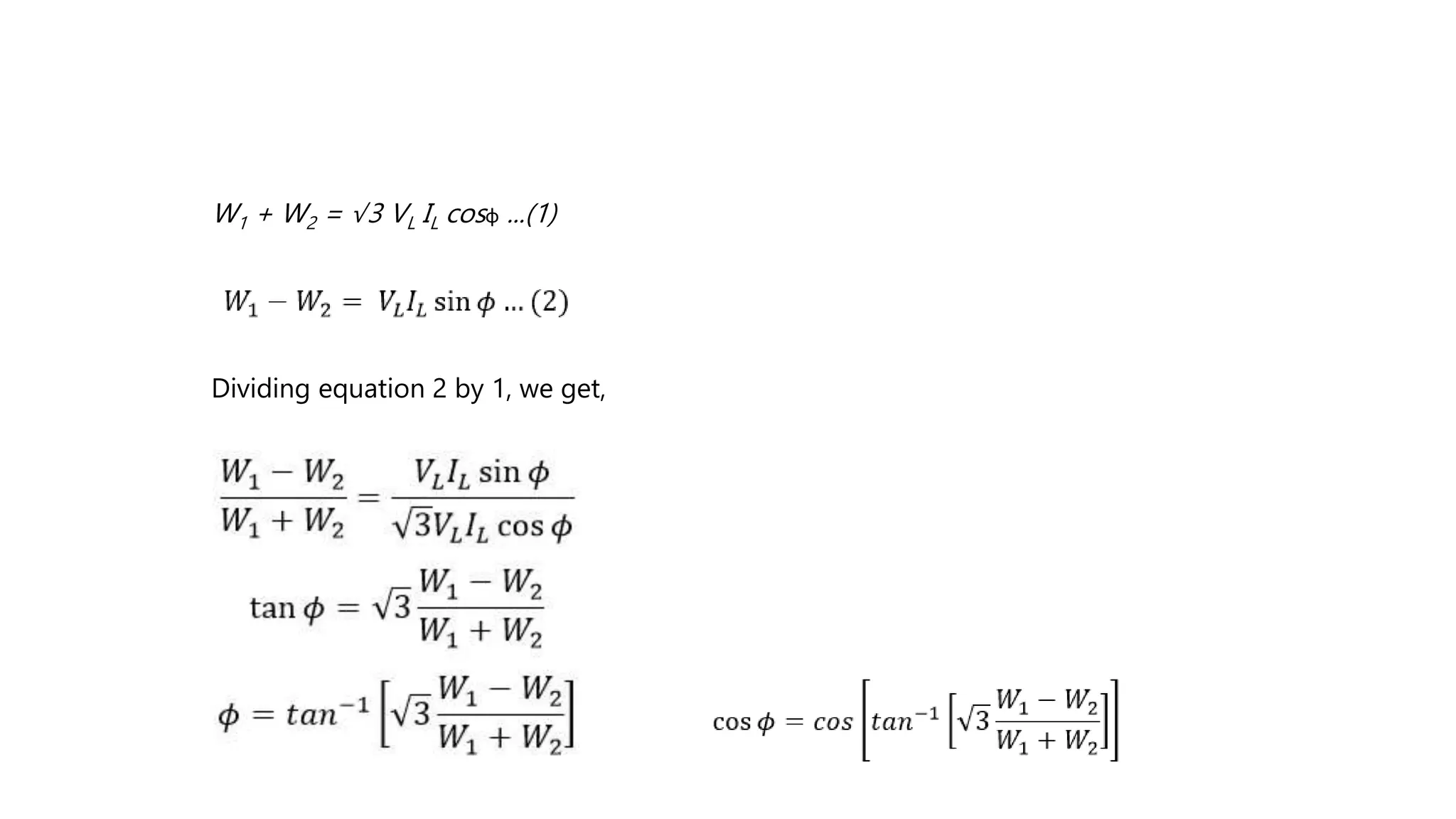
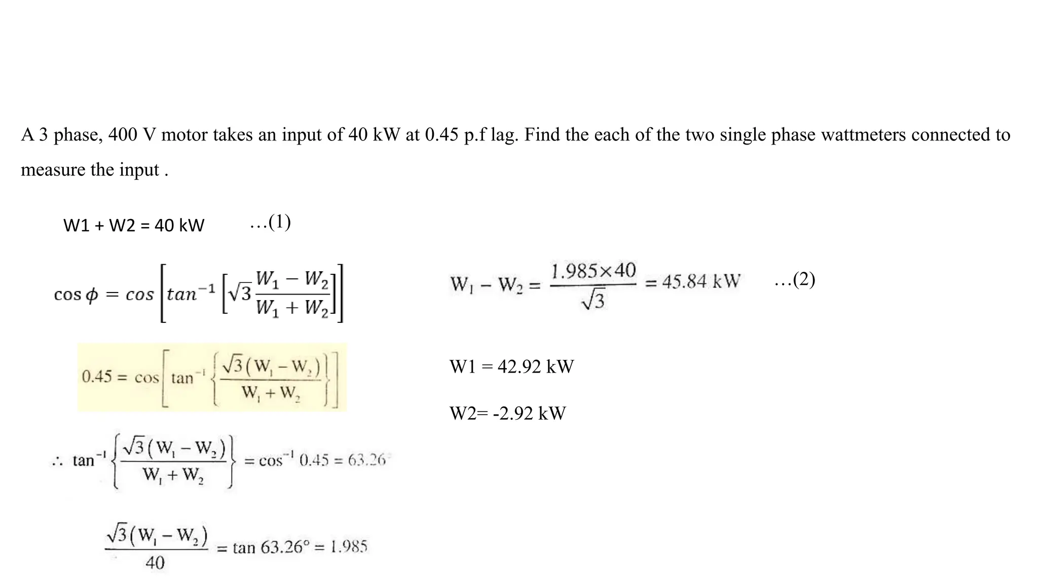
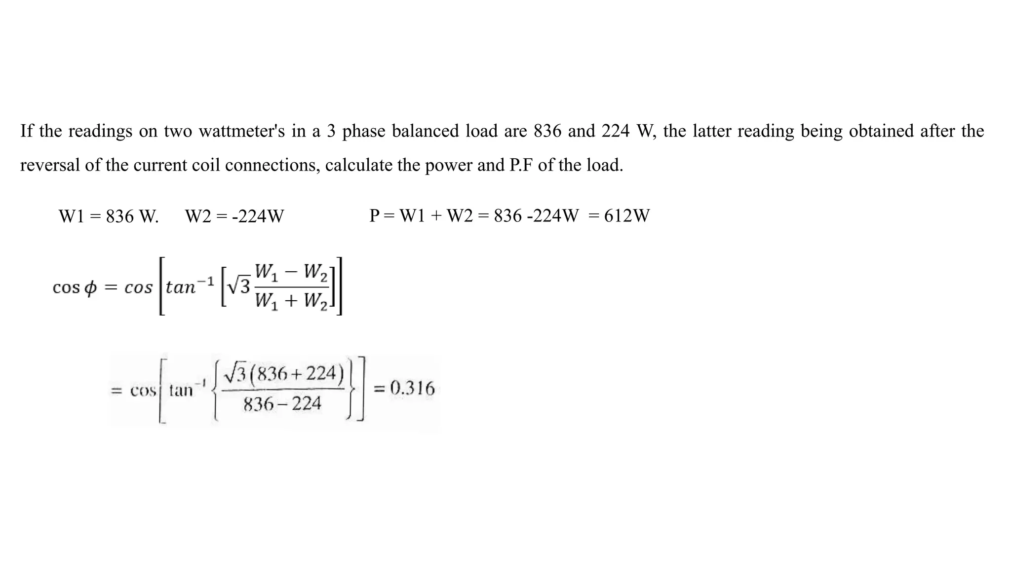
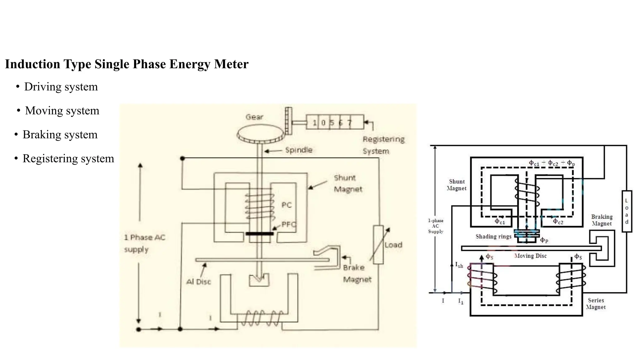
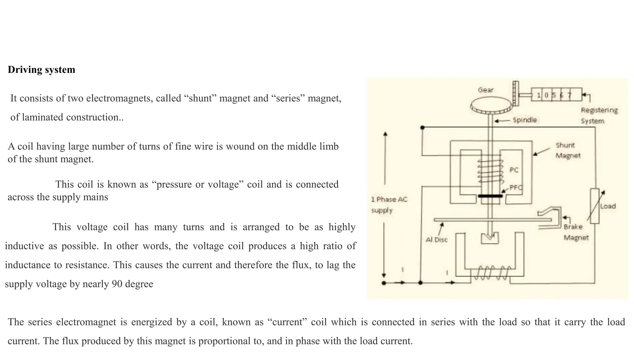
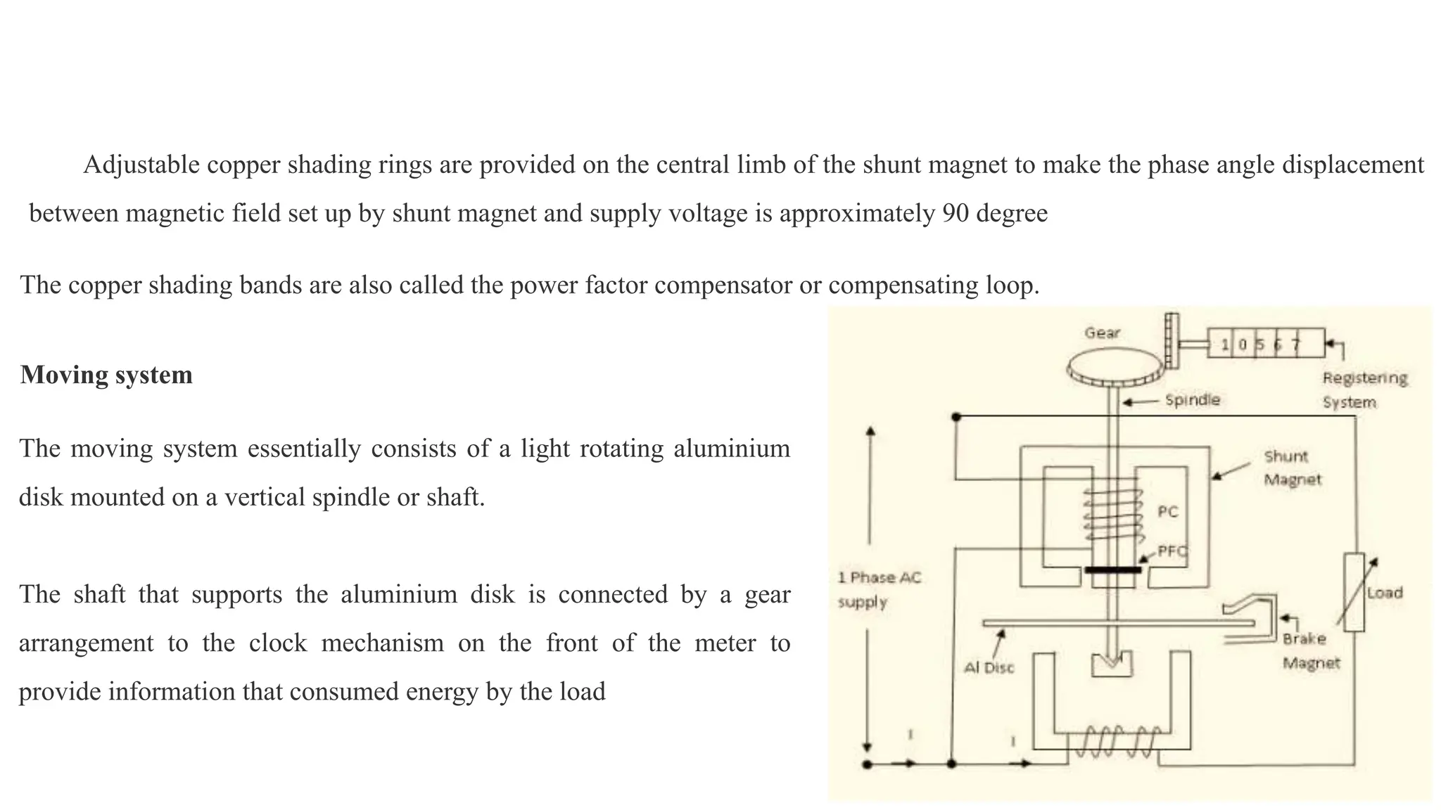
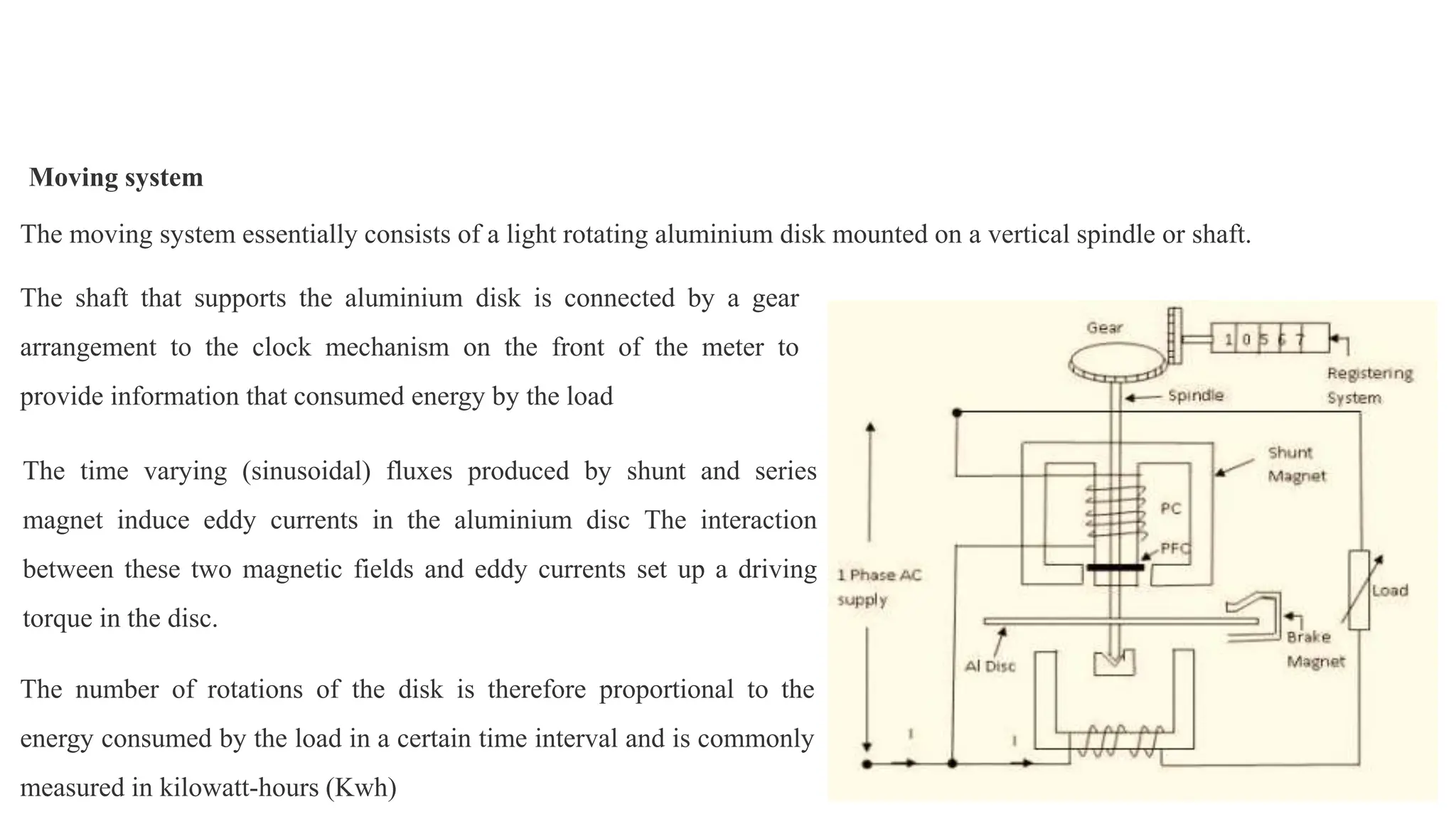
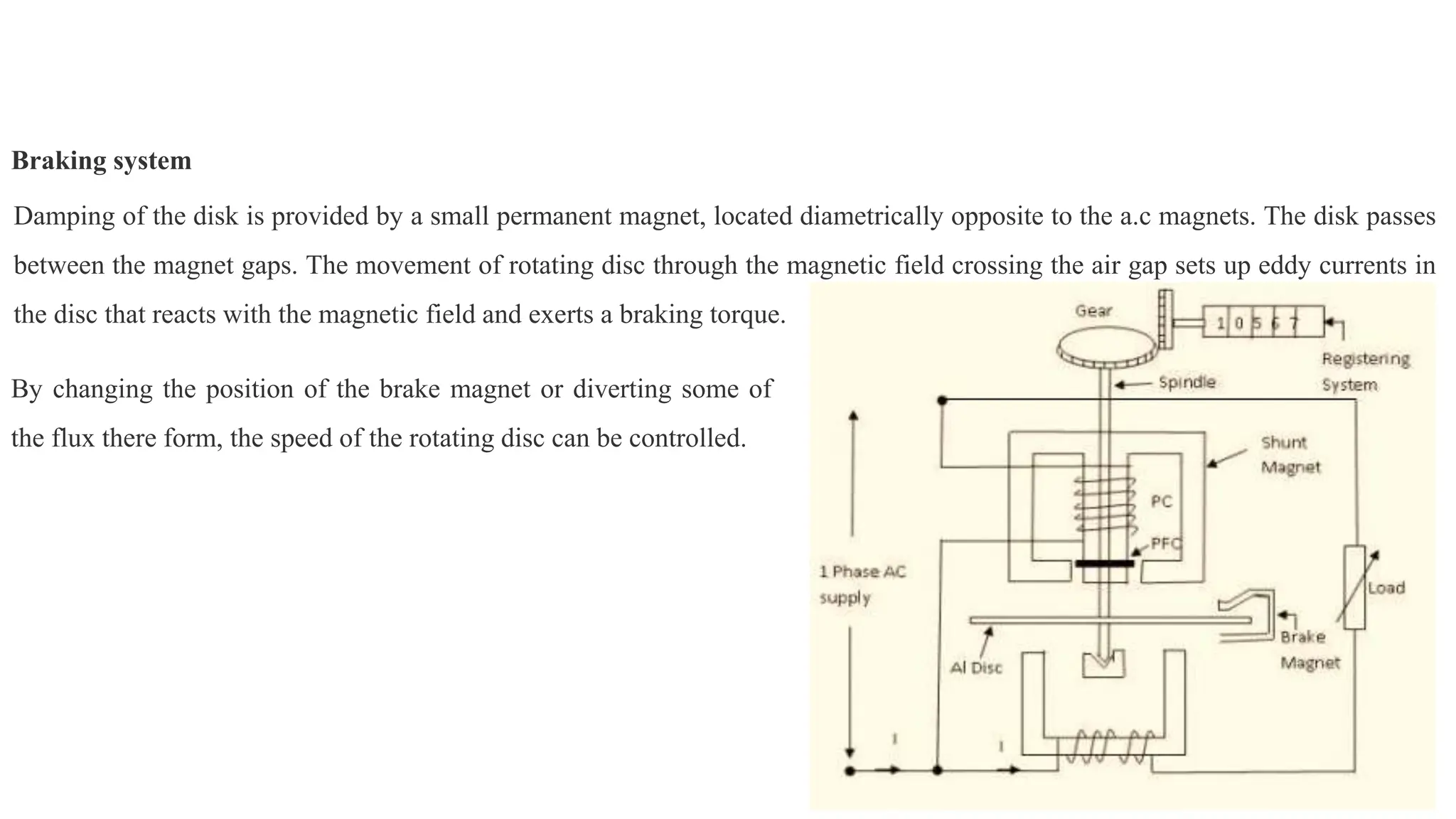
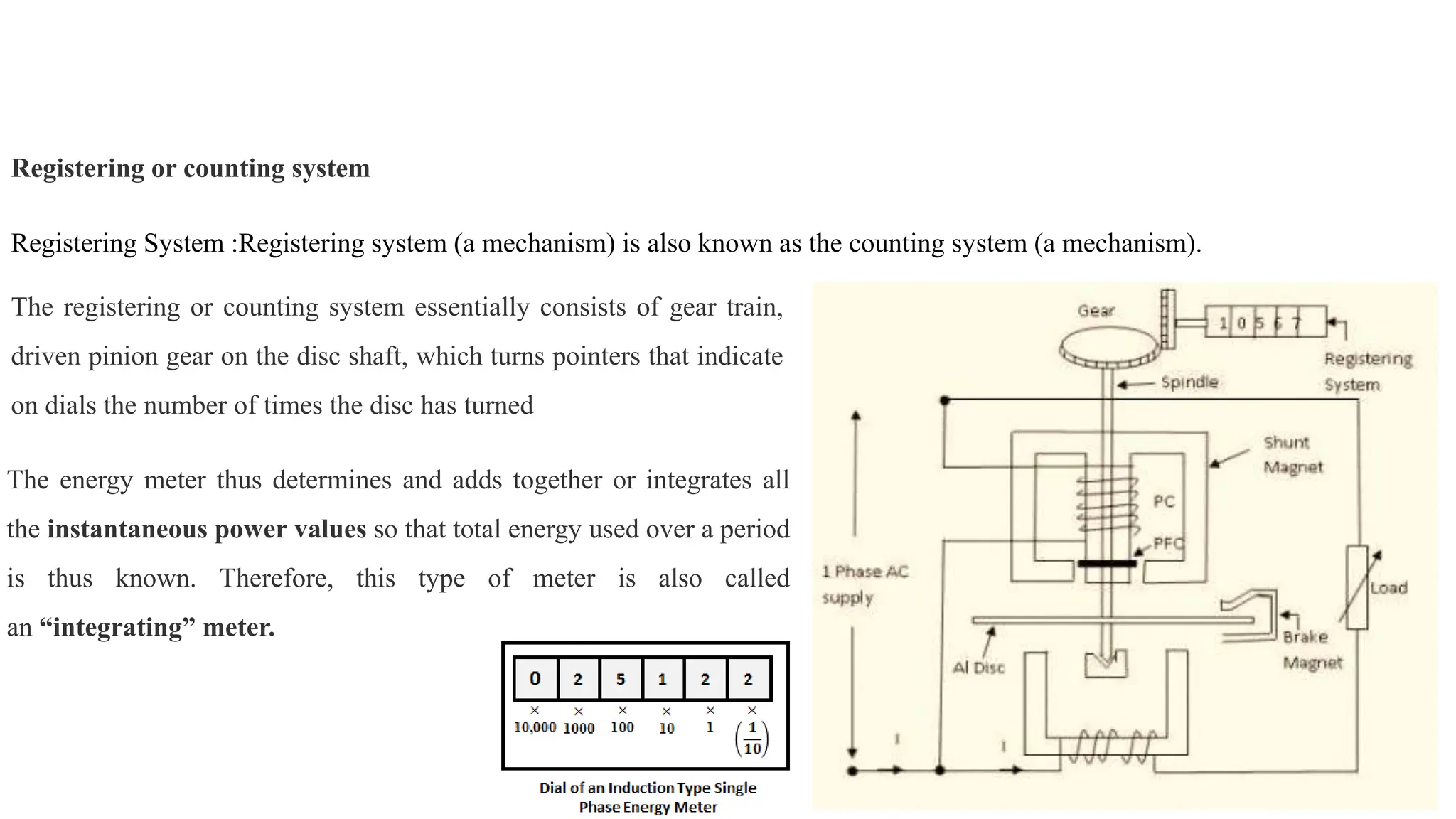
Module - II
Measurement of Power factor, Frequency and
Phase
Two Wattmeter Method with Balanced Load Condition
W1 + W2 = √3 VL IL cosφ ...(1)
Dividing equation 2 by 1, we get,
A 3 phase, 400 V motor takes an input of 40 kW at 0.45 p.f lag. Find the each of the two single phase wattmeters connected to
measure the input .
W1 + W2 = 40 kW
W1 = 42.92 kW
W2= -2.92 kW
…(1)
…(2)
If the readings on two wattmeter's in a 3 phase balanced load are 836 and 224 W, the latter reading being obtained after the
reversal of the current coil connections, calculate the power and P.F of the load.
P = W1 + W2 = 836 -224W = 612W
W1 = 836 W. W2 = -224W
A 3 phase star connected load draws a line current of 25 A. The load kVA and kW are 20 and 15 respectively. Find the reading
on each of the two wattmeters used to measure the three phase power.
P = W1 + W2 = 16kW …(1)
…(2)
W1 =11.464W. W2 = 4.536W
Two wattmeters are connected to measure the input to a 3 phase, 12 H.P, 50 Hz induction motor which works at a full load
efficiency of 85% and a power factor of 0.8. Find the readings of the two wattmeters. Also find the reactive power taken by the
I.M.
…(1)
…(2)
W1 =7439.87 W. W2 = 2943.66 W
Output of I.M =12 H.P =12*735.5= 8826 watts
Input of I.M = 8826 / 0.85 = 10, 383.53 watts
P = W1 + W2 = 10383.53 watts
Induction Type Single Phase Energy Meter
• Driving system
• Moving system
• Braking system
• Registering system
Driving system
It consists of two electromagnets, called “shunt” magnet and “series” magnet,
of laminated construction..
A coil having large number of turns of fine wire is wound on the middle limb
of the shunt magnet.
This coil is known as “pressure or voltage” coil and is connected
across the supply mains
This voltage coil has many turns and is arranged to be as highly
inductive as possible. In other words, the voltage coil produces a high ratio of
inductance to resistance. This causes the current and therefore the flux, to lag the
supply voltage by nearly 90 degree
The series electromagnet is energized by a coil, known as “current” coil which is connected in series with the load so that it carry the load
current. The flux produced by this magnet is proportional to, and in phase with the load current.
Adjustable copper shading rings are provided on the central limb of the shunt magnet to make the phase angle displacement
between magnetic field set up by shunt magnet and supply voltage is approximately 90 degree
The copper shading bands are also called the power factor compensator or compensating loop.
Moving system
The moving system essentially consists of a light rotating aluminium
disk mounted on a vertical spindle or shaft.
The shaft that supports the aluminium disk is connected by a gear
arrangement to the clock mechanism on the front of the meter to
provide information that consumed energy by the load
Moving system
The moving system essentially consists of a light rotating aluminium disk mounted on a vertical spindle or shaft.
The time varying (sinusoidal) fluxes produced by shunt and series
magnet induce eddy currents in the aluminium disc The interaction
between these two magnetic fields and eddy currents set up a driving
torque in the disc.
The shaft that supports the aluminium disk is connected by a gear
arrangement to the clock mechanism on the front of the meter to
provide information that consumed energy by the load
The number of rotations of the disk is therefore proportional to the
energy consumed by the load in a certain time interval and is commonly
measured in kilowatt-hours (Kwh)
Braking system
Damping of the disk is provided by a small permanent magnet, located diametrically opposite to the a.c magnets. The disk passes
between the magnet gaps. The movement of rotating disc through the magnetic field crossing the air gap sets up eddy currents in
the disc that reacts with the magnetic field and exerts a braking torque.
By changing the position of the brake magnet or diverting some of
the flux there form, the speed of the rotating disc can be controlled.
Registering or counting system
Registering System :Registering system (a mechanism) is also known as the counting system (a mechanism).
The registering or counting system essentially consists of gear train,
driven pinion gear on the disc shaft, which turns pointers that indicate
on dials the number of times the disc has turned
The energy meter thus determines and adds together or integrates all
the instantaneous power values so that total energy used over a period
is thus known. Therefore, this type of meter is also called
an “integrating” meter.
Three Phase Energy Meter
Power Factor Meters
• Single Phase Electrodynamometer type power factor
meter
• It consists of a fixed coil and pressure coil
• The fixed coil is split up into 2 parts and carries the maximum current of the
circuit.
• The current flowing through the fixed coil creates magnetic field around it.
• The two identical pressure coils A & B moving coil
• Current in the two coils carry same current
• R = w * L
• IB lags voltage V by 90 deg whereas IA is in phase with voltage V
• Therefore IB lags voltage IA by 90 deg
Weston Frequency Meter
Phase sequence Indicators
• There are two types of phase sequence indicators and they are:
• Rotating type
• Static type
Rotating Type Phase Sequence Indicators
• It works on the principle of induction motors

Electrical and electronics measurements Power Measurement

  • 1.
    Module - II Measurementof Power factor, Frequency and Phase
  • 3.
    Two Wattmeter Methodwith Balanced Load Condition
  • 4.
    Two Wattmeter Methodwith Balanced Load Condition
  • 5.
    W1 + W2= √3 VL IL cosφ ...(1)
  • 6.
    W1 + W2= √3 VL IL cosφ ...(1) Dividing equation 2 by 1, we get,
  • 7.
    A 3 phase,400 V motor takes an input of 40 kW at 0.45 p.f lag. Find the each of the two single phase wattmeters connected to measure the input . W1 + W2 = 40 kW W1 = 42.92 kW W2= -2.92 kW …(1) …(2)
  • 8.
    If the readingson two wattmeter's in a 3 phase balanced load are 836 and 224 W, the latter reading being obtained after the reversal of the current coil connections, calculate the power and P.F of the load. P = W1 + W2 = 836 -224W = 612W W1 = 836 W. W2 = -224W
  • 9.
    A 3 phasestar connected load draws a line current of 25 A. The load kVA and kW are 20 and 15 respectively. Find the reading on each of the two wattmeters used to measure the three phase power. P = W1 + W2 = 16kW …(1) …(2) W1 =11.464W. W2 = 4.536W
  • 10.
    Two wattmeters areconnected to measure the input to a 3 phase, 12 H.P, 50 Hz induction motor which works at a full load efficiency of 85% and a power factor of 0.8. Find the readings of the two wattmeters. Also find the reactive power taken by the I.M. …(1) …(2) W1 =7439.87 W. W2 = 2943.66 W Output of I.M =12 H.P =12*735.5= 8826 watts Input of I.M = 8826 / 0.85 = 10, 383.53 watts P = W1 + W2 = 10383.53 watts
  • 11.
    Induction Type SinglePhase Energy Meter • Driving system • Moving system • Braking system • Registering system
  • 12.
    Driving system It consistsof two electromagnets, called “shunt” magnet and “series” magnet, of laminated construction.. A coil having large number of turns of fine wire is wound on the middle limb of the shunt magnet. This coil is known as “pressure or voltage” coil and is connected across the supply mains This voltage coil has many turns and is arranged to be as highly inductive as possible. In other words, the voltage coil produces a high ratio of inductance to resistance. This causes the current and therefore the flux, to lag the supply voltage by nearly 90 degree The series electromagnet is energized by a coil, known as “current” coil which is connected in series with the load so that it carry the load current. The flux produced by this magnet is proportional to, and in phase with the load current.
  • 13.
    Adjustable copper shadingrings are provided on the central limb of the shunt magnet to make the phase angle displacement between magnetic field set up by shunt magnet and supply voltage is approximately 90 degree The copper shading bands are also called the power factor compensator or compensating loop. Moving system The moving system essentially consists of a light rotating aluminium disk mounted on a vertical spindle or shaft. The shaft that supports the aluminium disk is connected by a gear arrangement to the clock mechanism on the front of the meter to provide information that consumed energy by the load
  • 14.
    Moving system The movingsystem essentially consists of a light rotating aluminium disk mounted on a vertical spindle or shaft. The time varying (sinusoidal) fluxes produced by shunt and series magnet induce eddy currents in the aluminium disc The interaction between these two magnetic fields and eddy currents set up a driving torque in the disc. The shaft that supports the aluminium disk is connected by a gear arrangement to the clock mechanism on the front of the meter to provide information that consumed energy by the load The number of rotations of the disk is therefore proportional to the energy consumed by the load in a certain time interval and is commonly measured in kilowatt-hours (Kwh)
  • 15.
    Braking system Damping ofthe disk is provided by a small permanent magnet, located diametrically opposite to the a.c magnets. The disk passes between the magnet gaps. The movement of rotating disc through the magnetic field crossing the air gap sets up eddy currents in the disc that reacts with the magnetic field and exerts a braking torque. By changing the position of the brake magnet or diverting some of the flux there form, the speed of the rotating disc can be controlled.
  • 16.
    Registering or countingsystem Registering System :Registering system (a mechanism) is also known as the counting system (a mechanism). The registering or counting system essentially consists of gear train, driven pinion gear on the disc shaft, which turns pointers that indicate on dials the number of times the disc has turned The energy meter thus determines and adds together or integrates all the instantaneous power values so that total energy used over a period is thus known. Therefore, this type of meter is also called an “integrating” meter.
  • 18.
  • 19.
    Power Factor Meters •Single Phase Electrodynamometer type power factor meter
  • 20.
    • It consistsof a fixed coil and pressure coil • The fixed coil is split up into 2 parts and carries the maximum current of the circuit. • The current flowing through the fixed coil creates magnetic field around it. • The two identical pressure coils A & B moving coil • Current in the two coils carry same current • R = w * L • IB lags voltage V by 90 deg whereas IA is in phase with voltage V • Therefore IB lags voltage IA by 90 deg
  • 21.
  • 22.
    Phase sequence Indicators •There are two types of phase sequence indicators and they are: • Rotating type • Static type
  • 23.
    Rotating Type PhaseSequence Indicators • It works on the principle of induction motors