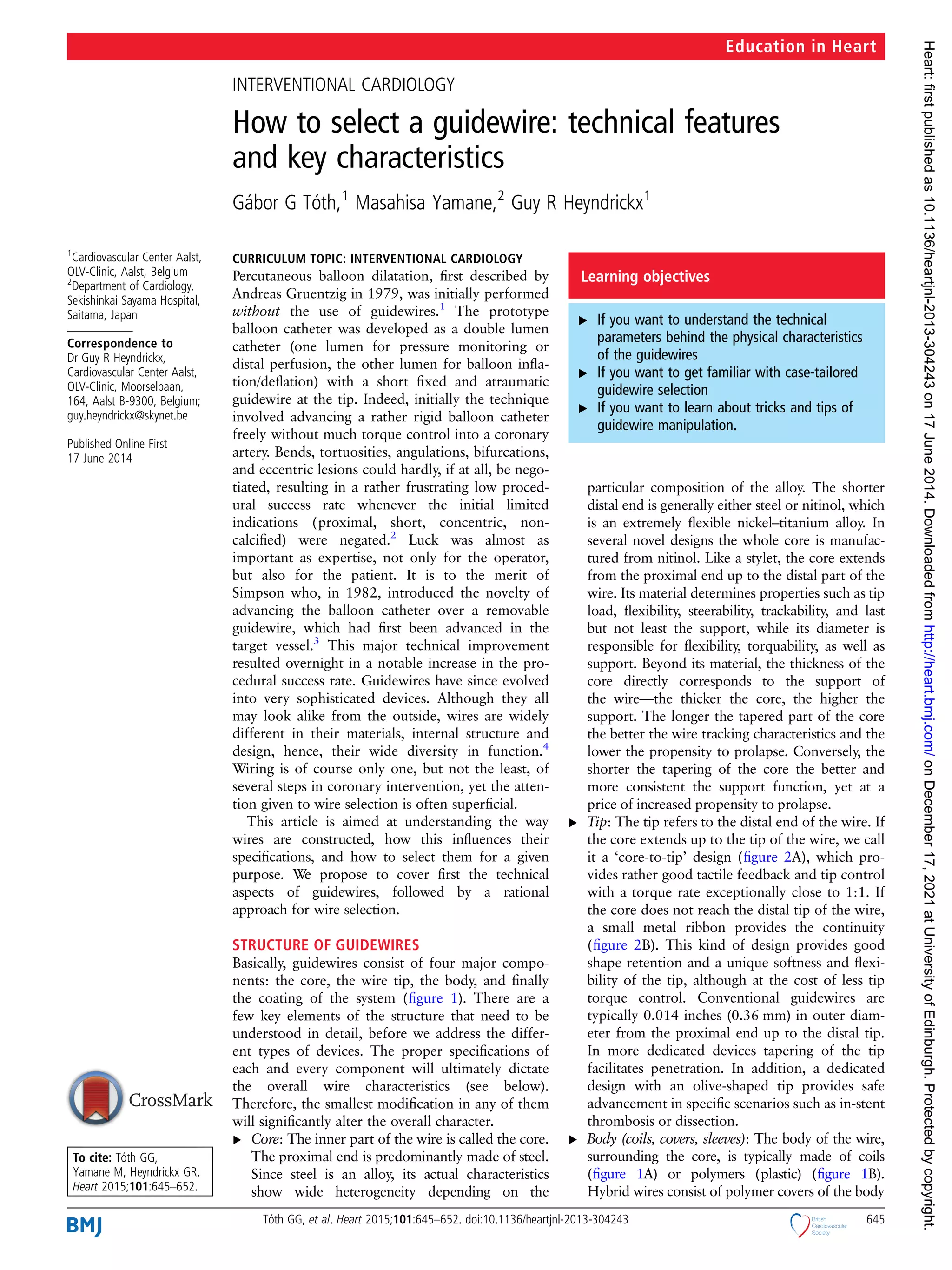
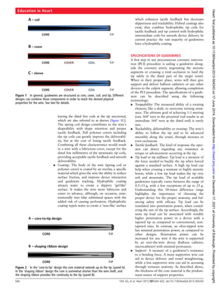
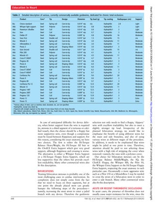
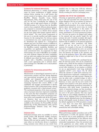
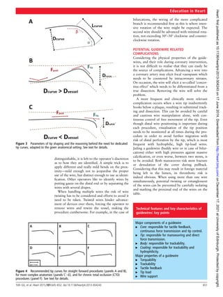
INTERVENTIONAL CARDIOLOGY
How to select a guidewire: technical features
and key characteristics
Gábor G Tóth,1
Masahisa Yamane,2
Guy R Heyndrickx1
1
Cardiovascular Center Aalst,
OLV-Clinic, Aalst, Belgium
2
Department of Cardiology,
Sekishinkai Sayama Hospital,
Saitama, Japan
Correspondence to
Dr Guy R Heyndrickx,
Cardiovascular Center Aalst,
OLV-Clinic, Moorselbaan,
164, Aalst B-9300, Belgium;
guy.heyndrickx@skynet.be
Published Online First
17 June 2014
To cite: Tóth GG,
Yamane M, Heyndrickx GR.
Heart 2015;101:645–652.
CURRICULUM TOPIC: INTERVENTIONAL CARDIOLOGY
Percutaneous balloon dilatation, first described by
Andreas Gruentzig in 1979, was initially performed
without the use of guidewires.1
The prototype
balloon catheter was developed as a double lumen
catheter (one lumen for pressure monitoring or
distal perfusion, the other lumen for balloon infla-
tion/deflation) with a short fixed and atraumatic
guidewire at the tip. Indeed, initially the technique
involved advancing a rather rigid balloon catheter
freely without much torque control into a coronary
artery. Bends, tortuosities, angulations, bifurcations,
and eccentric lesions could hardly, if at all, be nego-
tiated, resulting in a rather frustrating low proced-
ural success rate whenever the initial limited
indications (proximal, short, concentric, non-
calcified) were negated.2
Luck was almost as
important as expertise, not only for the operator,
but also for the patient. It is to the merit of
Simpson who, in 1982, introduced the novelty of
advancing the balloon catheter over a removable
guidewire, which had first been advanced in the
target vessel.3
This major technical improvement
resulted overnight in a notable increase in the pro-
cedural success rate. Guidewires have since evolved
into very sophisticated devices. Although they all
may look alike from the outside, wires are widely
different in their materials, internal structure and
design, hence, their wide diversity in function.4
Wiring is of course only one, but not the least, of
several steps in coronary intervention, yet the atten-
tion given to wire selection is often superficial.
This article is aimed at understanding the way
wires are constructed, how this influences their
specifications, and how to select them for a given
purpose. We propose to cover first the technical
aspects of guidewires, followed by a rational
approach for wire selection.
STRUCTURE OF GUIDEWIRES
Basically, guidewires consist of four major compo-
nents: the core, the wire tip, the body, and finally
the coating of the system (figure 1). There are a
few key elements of the structure that need to be
understood in detail, before we address the differ-
ent types of devices. The proper specifications of
each and every component will ultimately dictate
the overall wire characteristics (see below).
Therefore, the smallest modification in any of them
will significantly alter the overall character.
▸ Core: The inner part of the wire is called the core.
The proximal end is predominantly made of steel.
Since steel is an alloy, its actual characteristics
show wide heterogeneity depending on the
particular composition of the alloy. The shorter
distal end is generally either steel or nitinol, which
is an extremely flexible nickel–titanium alloy. In
several novel designs the whole core is manufac-
tured from nitinol. Like a stylet, the core extends
from the proximal end up to the distal part of the
wire. Its material determines properties such as tip
load, flexibility, steerability, trackability, and last
but not least the support, while its diameter is
responsible for flexibility, torquability, as well as
support. Beyond its material, the thickness of the
core directly corresponds to the support of
the wire—the thicker the core, the higher the
support. The longer the tapered part of the core
the better the wire tracking characteristics and the
lower the propensity to prolapse. Conversely, the
shorter the tapering of the core the better and
more consistent the support function, yet at a
price of increased propensity to prolapse.
▸ Tip: The tip refers to the distal end of the wire. If
the core extends up to the tip of the wire, we call
it a ‘core-to-tip’ design (figure 2A), which pro-
vides rather good tactile feedback and tip control
with a torque rate exceptionally close to 1:1. If
the core does not reach the distal tip of the wire,
a small metal ribbon provides the continuity
(figure 2B). This kind of design provides good
shape retention and a unique softness and flexi-
bility of the tip, although at the cost of less tip
torque control. Conventional guidewires are
typically 0.014 inches (0.36 mm) in outer diam-
eter from the proximal end up to the distal tip.
In more dedicated devices tapering of the tip
facilitates penetration. In addition, a dedicated
design with an olive-shaped tip provides safe
advancement in specific scenarios such as in-stent
thrombosis or dissection.
▸ Body (coils, covers, sleeves): The body of the wire,
surrounding the core, is typically made of coils
(figure 1A) or polymers (plastic) (figure 1B).
Hybrid wires consist of polymer covers of the body
Learning objectives
▸ If you want to understand the technical
parameters behind the physical characteristics
of the guidewires
▸ If you want to get familiar with case-tailored
guidewire selection
▸ If you want to learn about tricks and tips of
guidewire manipulation.
Education in Heart
Tóth GG, et al. Heart 2015;101:645–652. doi:10.1136/heartjnl-2013-304243 645
on
December
17,
2021
at
University
of
Edinburgh.
Protected
by
copyright.
http://heart.bmj.com/
Heart:
first
published
as
10.1136/heartjnl-2013-304243
on
17
June
2014.
Downloaded
from
leaving the distal free coils at the tip uncovered,
which are also referred to as sleeves (figure 1C).
The spring coil design contributes to the wire’s
shapeability with shape retention and proper
tactile feedback. Full polymer covers including
the tip coils can greatly improve the deliverabil-
ity, but at the cost of losing tactile feedback.
Combining all these characteristics would result
in a wire with a lubricious cover, except for the
distal few millimetres of the atraumatic tip coils,
providing acceptable tactile feedback and smooth
deliverability.
▸ Coating: The body of the wire (spring coil or
polymer cover) is coated by an overlay, a specific
material which gives the wire the ability to reduce
surface friction, and improve device interaction
and guidewire tracking. Hydrophilic coating
attracts water to create a slippery ‘gel-like’
surface. It makes the wire more lubricous and
easier to advance, although, on occasion, unin-
tentionally into false subintimal spaces with the
added risk of causing perforation. Hydrophobic
coating repels water to create a ‘wax-like’ surface
which enhances tactile feedback but decreases
slipperiness and trackability. Hybrid coatings also
exist; they combine hydrophobic tip coils for
tactile feedback and tip control with hydrophilic
intermediate coils for smooth device delivery. In
current practice the vast majority of guidewires
have a hydrophilic coating.
SPECIFICATIONS OF GUIDEWIRES
A first step in any percutaneous coronary interven-
tion (PCI) procedure is sailing a guidewire along-
side the coronary artery, negotiating the stenotic
segments or crossing a total occlusion to land the
tip safely in the distal part of the target vessel.
When in their proper place, wires will then give
support and deliver balloon catheters or any other
devices to the culprit segment, allowing completion
of the PCI procedure. The specifications of a guide-
wire can be described using the following
terminology:
▸ Torquability: The measured ability of a rotating
element, like a shaft, to overcome turning resist-
ance. The ultimate goal of achieving 1:1 steering
(one 360° turn at the proximal end results in an
immediate 360° turn at the distal end) is rarely
met.
▸ Trackability, deliverability or crossing: The wire’s
ability to follow the tip and to be advanced
smoothly along the vessel, through stenoses or
even occlusions.
▸ Tactile feedback: The kind of response the oper-
ator can detect regarding any resistance in
torque or advancement occurring at the tip.
▸ Tip load or tip stiffness: Tip load is a measure of
the force needed to buckle the tip when forced
against a standard surface. A high tip load can
help when crossing a resistant or highly stenotic
lesion, while a low tip load makes the tip very
soft and atraumatic. The tip load of available
guidewires typically varies between the range of
0.5–15 g, with a few exceptions of up to 25 g.
Understanding this 50-times difference range
highlights the importance of choosing the
proper device for the proper anatomy, and bal-
ancing safety with efficacy. Tip load can be
translated into penetration power, when consid-
ering the size of the tip surface. Accordingly, the
same tip load can be associated with notably
higher penetration power in a device with a
tapered tip as compared to conventional, non-
tapered ones. In contrast, an olive-tipped wire
has minimal penetration power, as compared to
other designs. Penetration power can be
increased for any wire if the wire is supported
by an over-the-wire device (balloon catheter,
microcatheter) with minimal protrusion.
▸ Support: A measure of a guidewire’s resistance
to a bending force. A more supportive wire can
aid in device delivery and vessel straightening,
while a less supportive wire can aid in accessing
through tortuous anatomy. As described above,
the thickness of the core material is the predom-
inant source of support properties.
Figure 1 In general, guidewires are structured as core, cover, coil, and tip. Different
designs can combine these components in order to reach the desired physical
properties for the wire. See text for details.
Figure 2 In the ‘core-to-tip’ design the core material extends up to the tip (panel A).
In the ‘shaping ribbon’ design the core is somewhat shorter than the wire itself, and
the shaping ribbon provides the continuity to the tip (panel B).
Education in Heart
646 Tóth GG, et al. Heart 2015;101:645–652. doi:10.1136/heartjnl-2013-304243
on
December
17,
2021
at
University
of
Edinburgh.
Protected
by
copyright.
http://heart.bmj.com/
Heart:
first
published
as
10.1136/heartjnl-2013-304243
on
17
June
2014.
Downloaded
from
WIRE SELECTION
Knowing the properties of guidewires in general as
well as the specifics of the different types is crucial.
However, it is advisable to master extensively (by
hands and mind) a few wires instead of having
superficial knowledge about many. This could make
the difference not only between success and failure,
but also between an economical or squandering
practice. The challenge will always be to choose the
wire with the best characteristics to tackle the
problem at hand5
(tables 1 and 2).
SIMPLE LESIONS
For the treatment of simple, short, concentric sten-
oses in the presence of a straightforward anatomy,
the top priority attribute required from the wire is
safety. For this purpose all the companies have
designed a so-called workhorse wire, which can be
the first choice in the vast majority of the proce-
dures. Since these wires are not meant to be used
in difficult or extreme anatomies, weighing any spe-
cific property is not required. So the design of a
workhorse wire aims to find an optimal compos-
ition, flexibility, and support. These wires are rather
atraumatic at the tip, and are associated with good
torquability and favourable trackability. For such
anatomy our choice would be the Hi-Torque
Balance MiddleWeight Universal II, the IQ or the
ChoICE Floppy. Many other commercial wires also
fit this description.
TORTUOUS ANATOMY
In cases of more complex anatomy the use of the
workhorse wires may fail or compromise the favour-
able outcome of the procedure. Negotiating severe
tortuosities in a vessel segment, distal to a target
lesion, may pose a challenge because positioning a
wire properly in the very distal segment of a vessel
may not be feasible. The potential risk is that the tip
of the wire, unable to negotiate the most distal curve,
will be left inside a bend during the procedure,
making it prone to vessel injury due to cyclic move-
ment of its tip during cardiac contraction. Therefore,
in the case of severe tortuosity the emphasis needs to
be placed on flexibility, lubricity and excellent track-
ability. Thus, for this kind of procedure the best
choice might be a wire with a polymer/hydrophilic
cover. Note that a soft tip is more favourable, since
the risk of vessel injury over multiple bends is
increased with a stiffer tip. It is also safe to make a
terminal loop of the tip of the wire which may then
facilitate distal landing. Therefore our first choice for
such anatomy would be the Hi-Torque Balance
Middle Weight, the IQ, the ChoICE Floppy, the
Whisper MS or the Pilot 50.
Table 1 Detailed description of various, currently commercially available guidewires, dedicated for ordinary anatomies
Product Core* Tip Design Diameter Tip load (g) Tip coating Radiopaque (cm) Support
Mtr Zinger Light Steel Spring coil Shaping ribbon 0.01400
ntp n/a Hydrophilic 3 Light
Mtr Cougar LS Nitinol Spring coil Shaping ribbon 0.01400
ntp n/a Hydrophilic 3 Light
Abb Whisper Light Support Steel Polymer Core-to-tip 0.01400
ntp 0.8 Hydrophilic 3 Light
Bsc ChoICE Floppy Steel Spring coil Core-to-tip 0.01400
ntp 0.8 Hybrid† 2.8 Light
Abb Powerturn Ultraflex Steel Coil Core-to-tip 0.01400
ntp 0.9 Hydrophilic 3 Light
Bsc PT 2 light support Nitinol Polymer Shaping ribbon 0.01400
ntp 2.5 Hydrophilic 2 Light
Mtr Zinger medium Steel Spring coil Shaping ribbon 0.01400
ntp n/a Hydrophilic 3 Moderate
Mtr Cougar MS Nitinol Spring coil Shaping ribbon 0.01400
ntp n/a Hydrophilic 3 Moderate
Abb Balance middle weight Nitinol Coil Shaping ribbon 0.01400
ntp 0.7 Hydrophilic 3 Moderate
Asa Sion Steel Coil Core-to-tip 0.01400
ntp 0.7 Hydrophilic 3 Moderate
Asa Fielder FC Steel Polymer Core-to-tip 0.01400
ntp 0.8 Hydrophilic 3 Moderate
Bsc Luge Steel Spring coil Core-to-tip 0.01400
ntp 0.9 Hybrid† 3 Moderate
Abb Powerturn flex Steel Coil Core-to-tip 0.01400
ntp 0.9 Hydrophilic 3 Moderate
Abb Whisper medium support Steel Polymer Core-to-tip 0.01400
ntp 1.0 Hydrophilic 3 Moderate
Bsc IQ Nitinol Spring coil Shaping ribbon 0.01400
ntp 1.1 Hydrophobic 2 Moderate
Abb Pilot 50 Steel Polymer Core-to-tip 0.01400
ntp 1.5 Hydrophilic 3 Moderate
Abb Cross-IT 100XT Steel Spring coil Core-to-tip 0.01000
tp 1.7 Hydrophilic 3 Moderate
Abb Pilot 150 Steel Polymer Core-to-tip 0.01400
ntp 2.7 Hydrophilic 3 Moderate
Bsc PT 2 moderate support Nitinol Polymer Shaping ribbon 0.01400
ntp 2.9 Hydrophilic 2 Moderate
Mtr Thunder Steel Spring coil Core-to-tip 0.01400
ntp n/a Hydrophilic 3 Extra
Mtr Zinger support Steel Spring coil Shaping ribbon 0.01400
ntp n/a Hydrophilic 3 Extra
Asa Grand slam Steel Spring coil Core-to-tip 0.01400
ntp 0.7 Hydrophobic 4 Extra
Abb Balance heavy weight Nitinol Coil Shaping ribbon 0.01400
ntp 0.7 Hydrophilic 4.5 Extra
Bsc ChoICE extra support Steel Spring coil Core-to-tip 0.01400
ntp 0.9 Hybrid† 2.8 Extra
Abb Powerturn Steel Coil Core-to-tip 0.01400
ntp 0.9 Hydrophilic 3 Extra
Bsc Choice PT extra support Steel Polymer Core-to-tip 0.01400
ntp 1.2 Hydrophilic 35 Extra
Abb Whisper extra support Steel Polymer Core-to-tip 0.01400
ntp 1.2 Hydrophilic 3 Extra
*Various alloys of steel, such as stainless steel, durasteel, etc, are not specified.
†Hybrid: distal 3 cm uncoated.
Abb, Abbott Laboratories, Abbott Park, Illinois, USA; Asa, Asahi Intecc Co, Aichi, Japan; Bsc, Boston Scientific Corp, Natick, Massachusetts, USA; Mtr, Medtronic Inc, Minneapolis,
Minnesota, USA; ntp, non-tapered, tp, tapered; 00
, inch.
Education in Heart
Tóth GG, et al. Heart 2015;101:645–652. doi:10.1136/heartjnl-2013-304243 647
on
December
17,
2021
at
University
of
Edinburgh.
Protected
by
copyright.
http://heart.bmj.com/
Heart:
first
published
as
10.1136/heartjnl-2013-304243
on
17
June
2014.
Downloaded
from
In case of anticipated difficulty for device deliv-
ery, when better support from the wire is required
(ie, stenosis in a distal segment of a tortuous or calci-
fied vessel), then the choice should be a floppy but
more supportive wire, even though a compromise
must be found between floppiness and support. For
this reason, considering the exact anatomy, we have
two choices. The first is either the Hi-Torque
Balance HeavyWeight, the Hi-Torque All Star or
the ChoICE Extra Support which give very good
support, although floppiness and crossing is worse.
The alternative is either a Whisper Extra Support
or a Hi-Torque Floppy Extra Support, which are
less supportive than the others but provide excel-
lent trackability. Many other commercial wires also
fit this description.
BIFURCATIONS
Treating bifurcation stenoses is probably one of the
most challenging cases in cardiac intervention. Its
complexity does not simply come from the fact
that we need to focus on three segments, but at
one point the already placed stent can greatly
hamper the following steps of the procedure—
namely, recrossing the stent struts to enter a jailed
branch with any device. Therefore the guidewire
selection not only needs to find a floppy, ‘slippery’
wire with excellent trackability, but also to meet a
slightly stronger tip load. Irrespective of the
planned bifurcation strategy, we would like to
emphasise the benefit of using different wires for
the main and side branches, and also of using
various wires at different stages of the procedure.
In addition, it needs to be emphasised that wires
might be jailed at one point in time. Therefore,
attention should be paid to not selecting those
wires with a high risk of stripping the cover when
removed—namely, the ones with a polymer cover.
Our choice for bifurcation stenoses can be the
Hi-Torque Balance MiddleWeight, the IQ, the
ChoICE Floppy, the Whisper MS, the Pilot 50,
the Whisper Extra Support or the Hi-Torque Floppy
Extra Support, respecting the exact anatomy in each
particular case. Occasionally a more aggressive wire
such as a Pilot 150 or a MiracleBros 3 may be needed
to cross the struts of a bifurcation stent in order to
enter a side branch. Many other commercial wires
also fit this description.
ACUTE OR RECENT THROMBOTIC OCCLUSIONS
In acute cases, the presence of thrombus does not
usually cause major resistance for the wire, since the
Table 2 Detailed description of various, currently commercially available guidewires, dedicated for chronic total occlusions
Product Core* Tip Design Diameter Tip load (g) Tip coating Radiopaque (cm) Support
Bsc Choice standard Steel Spring coil Core-to-tip 0.01400
ntp n/a Hydrophilic 2.8 Light
Abb Whisper light support Steel Polymer Core-to-tip 0.01400
ntp 0.8 Hydrophilic 3 Light
Abb Powerturn Ultraflex Steel Coil Core-to-tip 0.01400
ntp 0.9 Hydrophilic† 3 Light
Asa Sion Steel Coil Core-to-tip 0.01400
ntp 0.7 Hydrophilic 3 Moderate
Asa Fielder XT Steel Polymer Core-to-tip 0.00900
tp 0.8 Hydrophilic 16 Moderate
Asa Gaia First Steel Double coil Core-to-tip 0.01000
tp‡ 1.5 Hydrophilic 15 n/a
Asa Miracle 3 Steel Spring coil Core-to-tip 0.01400
ntp 3.0 Hydrophobic 11 Moderate
Asa UltimateBros 3 Steel Spring coil Core-to-tip 0.01400
ntp 3.0 Hydrophilic 11 Moderate
Mtr Provia 3 Steel Spring coil Shaping ribbon 0.01400
ntp 3.0 Hydrophilic† 3 Moderate
Asa Gaia Second Steel Double coil Core-to-tip 0.01100
tp‡ 3.5 Hydrophilic 15 n/a
Abb Pilot 200 Steel Polymer Core-to-tip 0.01400
ntp 4.1 Hydrophilic 3 Moderate
Asa Miracle 4.5 Steel Spring coil Core-to-tip 0.01400
ntp 4.5 Hydrophobic 11 Moderate
Abb Cross-IT 200XT Steel Spring coil Core-to-tip 0.01000
tp 4.7 Hydrophilic 3 Moderate
Abb Progress 40 Steel Spring coil Core-to-tip 0.01200
ntp 4.8 Hydrophilic† 3 Moderate
Mtr Provia 6 Steel Spring coil Shaping ribbon 0.01400
ntp 6.0 Hydrophilic† 3 Moderate
Asa Miracle 6 Steel Spring coil Core-to-tip 0.01400
ntp 6.0 Hydrophobic 11 Moderate
Abb Cross-IT 300XT Steel Coil Core-to-tip 0.01000
tp 6.2 Hydrophilic 3 Moderate
Abb Cross-IT 400XT Steel Coil Core-to-tip 0.01000
tp 8.7 Hydrophilic 3 Moderate
Asa Confianza Pro Steel Spring coil Core-to-tip 0.00900
tp 9.0 Hydrophilic† 20 Moderate
Mtr Provia 9 Steel Spring coil Shaping ribbon 0.00900
tp 9.0 Hydrophilic† 3 Moderate
Abb Progress 80 Steel Coil Core-to-tip 0.01200
ntp 9.7 Hydrophilic† 3 Moderate
Asa Confianza Pro 12 Steel Spring coil Core-to-tip 0.00900
tp 12.0 Hydrophilic† 20 Moderate
Asa Miracle 12 Steel Spring coil Core-to-tip 0.01400
ntp 12.0 Hydrophobic 11 Moderate
Abb Progress 140T Steel Coil Core-to-tip 0.01000
tp 12.5 Hydrophilic† 3 Moderate
Abb Progress 200T Steel Coil Core-to-tip 0.00900
tp 13.3 Hydrophilic† 3 Moderate
Abb Progress 120 Steel Coil Core-to-tip 0.01000
ntp 13.9 Hydrophilic† 3 Moderate
Mtr Provia 12 Steel Spring coil Shaping ribbon 0.00900
tp 12.0 Hydrophilic† 3 Extra
Mtr Provia 15 Steel Spring coil Shaping ribbon 0.00900
tp 15.0 Hydrophilic† 3 Extra
*Various alloys of steel, such as stainless steel, durasteel, etc, are not specified.
†Hydrophilic, except very distal tip.
‡Tapered with straight segment at the distal 15 mm (Gaia First) or 6 mm (Gaia Second).
Abb, Abbott Laboratories, Abbott Park, Illinois, USA; Asa, Asahi Intecc Co, Aichi, Japan; Bsc, Boston Scientific Corp, Natick, Massachusetts, USA; Mtr, Medtronic Inc, Minneapolis,
Minnesota, USA; ntp, non-tapered, tp, tapered; 00
, inch.
Education in Heart
648 Tóth GG, et al. Heart 2015;101:645–652. doi:10.1136/heartjnl-2013-304243
on
December
17,
2021
at
University
of
Edinburgh.
Protected
by
copyright.
http://heart.bmj.com/
Heart:
first
published
as
10.1136/heartjnl-2013-304243
on
17
June
2014.
Downloaded
from
thrombus is still fresh and mainly quite soft. These
situations become more difficult when it is not pos-
sible to visualise the morphology of the culprit
lesions and the vessel distal to the stenosis.
Therefore the key to wiring is to cross the occlusion
safely and quickly and to be able to advance the wire
softly and atraumatically to the distal lumen. In the
case of ST elevation myocardial infarction (STEMI)
in particular, the culprit lesion can be complicated
by the presence of a disruptive flap as a consequence
of plaque rupture. Using a soft wire is perhaps less
risky than using a stiffer one, especially a hydro-
philic or coated wire, which can easily find its way
subintimally without being noticed. Therefore our
choice for STEMI is the Hi-Torque Balance
MiddleWeight, the IQ, or the ChoICE Floppy.
Hydrophilic wires with a higher tip load—that is,
the Whisper MS or the Pilot 50—may also have a
slightly increased risk for subintimal dissection,
although their use may be favourable in particular
cases, when occlusion occurs within a ‘chronically
stenosed’ or even tortuous coronary segment. For
in-stent thrombosis the use of an olive-tipped guide-
wire (Magnum, Biotronik GmbH, Germany) with a
0.028 inch olive, can be considered a safe wire to
negotiate potentially malapposed stent struts.
Subacute coronary occlusions represent a com-
pletely different substrate. Here, the thrombus
material has become much harder, and it can there-
fore be a challenge to pass the thrombotic burden.
For these settings, besides the above mentioned
wires, we need to consider other wires with a
stiffer tip and higher tip load that can successfully
facilitate the crossing. However, handling such a
device requires much more care, for the reasons
described above. Our preferences are the Pilot 50,
the Fielder XT or the Pilot 150. Many other com-
mercial wires also fit this description.
CHRONIC TOTAL OCCLUSIONS
Crossing chronic total occlusions (CTOs) require a
set of dedicated CTO guidewires as well as addi-
tional technical skills. The key features to recognise
when selecting a guidewire are: (1) tapered tip or
not; (2) polymer cover or not; (3) stiffness; and (4)
trackability. It is not uncommon to exchange one
set of wires for another during a complex proced-
ure, which is done usually through a microcatheter.
So balloon trapping inside the guide catheter is a
routine measure in order not to lose the wire pos-
ition or avoid wire tip injury when there is a need
for an over-the-wire system exchange.
Anterograde approach: Potential choices cover a
wide range of devices. For a focal (<10–20 mm
length), tapered, straight CTO without a side
branch, the first choice is a soft, tapered, polymer
covered wire for initial (micro) channel tracking. At
the other end of the spectrum—as in intravascular
ultrasound guided re-entry from subintimal space
to true lumen—a tapered, high gram stiff wire with
a larger secondary curve may be required. Because
direct linear transmission of wire manipulation to
the tip is often attenuated, wiring by drilling or
penetration is commonly adopted. Wire escalation
was initially advised, often starting with a soft
tapered polymer covered wire in the above men-
tioned shorter CTOs, to be followed by a middle
weight, spring coil wire and then, if needed, a
stiffer device. Once a wire passes the hard, resistant
part, it is reasonable to exchange (over a micro-
catheter) the wire for a softer, manoeuvrable wire
so as to minimise any expansion of the subintimal
space at the entry point (either in the proximal or
distal CTO caps), in order to reach the distal true
lumen—that is, a wire step-down. Parallel wire
technique follows the same principle. In case the
first wire fails to enter the distal true lumen, advan-
cing a second stiffer, tapered wire, while leaving
the first wire in place as a road map to the target,
may help in finding a different entry point, thereby
avoiding enlarging the subintimal space created by
the first wire. Co-axial wiring over a double lumen
microcatheter provides the best platform to support
the second wire through the over-the-wire lumen.
Most recent wire designs such as the Gaia series
allow for better active wire control inside CTOs,
realising 1:1 torque response with a durable
double-coil structure, pre-shaped tip, and round
core design to minimise whip motion.
Retrograde approach: The choice and manipulation
of guidewires play an even more crucial role in the
combined retrograde–anterograde approach for
CTO, as first described by Kato et al.6
Detailed tech-
nical aspects are beyond the scope of this article.
Controlling the guidewire remains key for this novel
and complex approach, especially in steering through
collateral channels to reach the distal end of the CTO
as well as (re-)entering the other side of the true
lumen. Soft polymer coated wires—either tapered,
such as Fielder XT-R, or non-tapered, such as Sion
wire or Whisper LS—are the mainstream in collateral
crossing, either in septal, epicardial or atrial channels,
with slow to-and-fro wire rotation being the essence
of safe crossing. While CTO crossing can be achieved
by many different strategies (kissing or wire marking
technique, direct retrograde crossing, controlled
anterograde and retrograde subintimal tracking
(CART), and reverse CART, retrograde wiring should
aim at close apposition with an anterograde wire
inside the CTO, which will facilitate wire re-entry by
anterograde balloon inflation (ie, reverse CART).
Among the most frequently used retrograde wires are
Miraclebros 3, Gaia 1 and Gaia 2 over the closely
positioned microcatheter. Confianza Pro 9 and
Confianza Pro 12 are often applied in a very limited,
hard segment, while other operators use a Pilot 200
or Fielder XT as a retrograde ‘knuckle’ wiring to
facilitate subintimal passage in a long, calcified occlu-
sion. However, ‘knuckling’ should be reserved as a
last resort, since it may potentially enlarge the dissec-
tion plane and shear off the side branches in an
unpredictable way. Many other commercial wires
also fit this description.
GUIDEWIRES DESIGNED FOR SPECIAL
SCENARIOS
For the sake of completeness a couple of specially
designed guidewires also need to be mentioned.
Education in Heart
Tóth GG, et al. Heart 2015;101:645–652. doi:10.1136/heartjnl-2013-304243 649
on
December
17,
2021
at
University
of
Edinburgh.
Protected
by
copyright.
http://heart.bmj.com/
Heart:
first
published
as
10.1136/heartjnl-2013-304243
on
17
June
2014.
Downloaded
from
Guidewire for rotational atherectomy
Rotational atherectomy is a widely accepted tech-
nique for lesion modification of highly calcified
stenoses before stenting. As is well known, this
system consists of an engine, a burr, and a so-called
RotaWire (Boston Scientific Corp, Natick,
Massachusetts, USA), which plays the role of the
axle for the burr. Considering the bulkiness of
the burr, and its high speed rotation of 150 000–
180 000 revs/min, it is obvious that the RotaWire
needs to have completely different physical proper-
ties compared to conventional guidewires. With its
0.009 inch diameter it is a thinner device (except
for the more distal radio-opaque segment which is
0.014 inches).7
The most crucial requirement of
this wire is to provide excellent and stable support
function for the rotating burr. For obvious reasons
a conventional core cover coated structure had to
be abandoned and replaced by a homogeneous
stainless steel wire. For these reasons, in addition to
its length (300 mm), the manipulative properties of
the RotaWire—namely trackability, flexibility and
torquability—are significantly weaker compared to
most conventional wires. To compensate for these
shortcomings, two types of RotaWires are available:
one with moderate support but better trackability,
and one with extra support but poorer trackability.
In difficult cases where the lesion cannot be wired
properly with a RotaWire, conventional wiring
with a more appropriate wire is advised, where-
upon exchange for a RotaWire over a microcatheter
is performed.
Guidewire for intracoronary pressure/flow
measurement
Measurements of physiological parameters such as
intracoronary pressure and flow during diagnostic
and interventional procedures are now routinely
available and frequently applied for decision
making during PCI. Guided revascularisation by
measuring fractional flow reserve (FFR) is well
established and strongly recommended in specific
clinical scenarios. FFR is determined using a special
guidewire, mounted with a distal pressure sensor.8
The mechanical properties of the most recent gene-
ration of pressure wires have improved considerably
to the point that their manipulative properties are
becoming indistinct from most conventional work-
horse wires, and compatible with all the PCI mater-
ial. However, their use in more challenging
anatomies can be still cumbersome. Two models are
available at the moment: the PressureWire (St Jude
Medical Inc, St Paul, Massachusetts, USA), and the
PrimewirePrestige (Volcano Corp, San Diego,
California, USA).
Extension wires
Dedicated extension wires are available in various
brands (Galeo EW
, Biotronik GmbH, Germany;
Doc Wire, Abbott Laboratories, Abbott Park,
Illinois, USA, etc) and are useful, if not essential, in
cases where an over-the-wire device is mandatory.
Using extension wires allows an easy switch from
standard wire to long wire (320 cm) whenever
equipped with a dedicated proximal connector,
thereby avoiding the need for exchanging wires.
SHAPING THE TIP OF THE GUIDEWIRE
Choosing an appropriate guidewire is just the first
step to safe and successful wire advancement. The
proper shaping of the tip can enhance its manoeuv-
rability, and so it can be the second key to a
straightforward procedure. As no clear recommen-
dations about optimal tip curves exist, we would
like to share our experience in this matter. As
shown in figure 3A, preparation of the tip curve
means optimisation of several geometrical proper-
ties. The wire tip needs to be shaped with respect
to the optimal and case specific length (L), and
primary (α) and, if needed, secondary (β) angula-
tions. These three components will define the curve
diameter (D). In addition to the physical properties
of a guidewire, these parameters will define
whether or not we can use it for the given
anatomy. For example, in the case of a challenging
bifurcation, a well prepared tip curve can provide
an ideal and well controlled transmission of the
force (F) between the hands of the operator and
the tip of the guidewire (figure 3B), while a default
angulation might lead to loss of force and control
(figure 3C).
Some wires are available with a preshaped tip (ie,
Pilot 50 and Gaia series). This can be considered a
default curve, which fits the majority of anatomical
variations, although it can be rather insufficient in
several other situations. In our practice, as default,
we use an approximately 3 mm long, moderately
angulated (α≈45°) curve (figure 4A, B) which
allows the operator to tackle with continuous rota-
tional advancement moderately complicated tortu-
osities, bifurcations and tight stenoses. Shaping the
wire tip either with a rounded J-shape or with a
sharp angle may be sufficient to start a procedure.
However, in many cases the tip curve needs to be
adapted more properly to the given anatomy, espe-
cially when negotiating pronounced tortuosities or
bifurcations with sharp bends. Considering the
variety of anatomical settings, our best recommen-
dation is to adapt the length and angulation of the
tip curve to the given anatomy. This may require
long, sharp or even multiple angulations in the tip
(figure 4C–E). Tackling CTOs, as described above,
requires special, dedicated wires, but the shaping of
the tip is still equally crucial. As shown in figure 4F,
the default angulation for CTO procedures consists
of a very short (no more than approximately
1 mm), sharply angulated curve, allowing for
powerful but well controllable drilling.
GUIDEWIRE MANAGEMENT
When performing complex procedures such as PCI
of bifurcations or CTOs, the operator might face
the need for two or more guidewires at the same
time. Accurate identification of the different wires
is crucial in order to avoid unnecessary or even
unintended manipulation. Since the proximal ends
of the guidewires are rather similar and barely
Education in Heart
650 Tóth GG, et al. Heart 2015;101:645–652. doi:10.1136/heartjnl-2013-304243
on
December
17,
2021
at
University
of
Edinburgh.
Protected
by
copyright.
http://heart.bmj.com/
Heart:
first
published
as
10.1136/heartjnl-2013-304243
on
17
June
2014.
Downloaded
from
distinguishable, it is left to the operator’s discretion
as to how they are identified. A simple trick is to
apply different and really mild bends on the prox-
imity—mild enough not to jeopardise the proper
use of the wire, but distinct enough to use as identi-
fication. Other operators like to identify wires by
putting gauze on the distal end or by separating the
wires with several drapes.
When handling multiple wires the risk of wire
twisting has to be considered and efforts to avoid it
need to be taken. Twisted wires hinder advance-
ment of devices over them, forcing the operator to
remove wires and rewire the vessel, making the
procedure cumbersome. For example, in the case of
bifurcations, the wiring of the more complicated
branch is recommended first as this is where inten-
sive rotation of the wire might be expected. The
second wire should be advanced with minimal rota-
tion, not exceeding 30°–30° clockwise and counter-
clockwise rotation.
POTENTIAL GUIDEWIRE RELATED
COMPLICATIONS
Considering the physical properties of the guide-
wires, and their role during coronary intervention,
it is not difficult to realise that they can easily be
the source of complications. Advancing a wire into
a coronary artery may elicit focal vasospasm which
needs to be countered by intracoronary nitrates.
On occasion, the wire will elicit a so-called ‘concer-
tina effect’ which needs to be differentiated from a
true dissection. Removing the wire will solve the
problem.
A more frequent and clinically more relevant
complication occurs when a wire tip inadvertently
hooks below a plaque, resulting in subintimal track-
ing and dissection. This can be avoided by careful
and cautious wire manipulation alone, with con-
tinuous control of free movement of the tip. Even
though distal wire positioning is important during
each procedure, visualisation of the tip position
needs to be monitored at all times during the pro-
cedure in order to avoid further migration with
risk of distal perforation by the tip, which is most
frequent with hydrophilic, high tip-load wires.
Jailing a guidewire (buddy wire or in case of bifur-
cations) either with high pressures against massive
calcification, or even worse, between two stents, is
to be avoided. Both manoeuvres risk stent fracture
or denudation of the cover during pullback.
Considering that this may result in foreign material
being left in the lumen, its thrombotic risk is
indeed obvious. When using more than one wire
simultaneously, potential twisting or entanglement
of the wires can be prevented by carefully isolating
and marking the proximal end of the wires on the
table.
Figure 4 Recommended tip curves for straight forward procedures (panels A and B),
for more complex anatomies (panels C –E), and for chronic total occlusion (CTO)
procedures (panel F). See text for details.
Figure 3 Parameters of tip shaping and the reasoning behind the need for dedicated
tip curves, adapted to the given anatomical setting. See text for details.
Technical features and key characteristics of
guidewires: key points
Major components of a guidewire
▸ Core: responsible for tactile feedback,
continuous force transmission and tip control.
▸ Tip: responsible for manoeuvring and direct
force transmission.
▸ Body: responsible for trackability.
▸ Coating: responsible for trackability and
hydrophilicity.
Major properties of a guidewire
▸ Torquability
▸ Trackability
▸ Tactile feedback
▸ Tip load
▸ Wire support
Education in Heart
Tóth GG, et al. Heart 2015;101:645–652. doi:10.1136/heartjnl-2013-304243 651
on
December
17,
2021
at
University
of
Edinburgh.
Protected
by
copyright.
http://heart.bmj.com/
Heart:
first
published
as
10.1136/heartjnl-2013-304243
on
17
June
2014.
Downloaded
from
CONCLUSION
The available stock of guidewires to choose from
can prove challenging to the operator looking for a
specific wire.4
In view of the importance of guide-
wire selection to tackle specific lesions, it is disturb-
ing to note the lack of knowledge in this regard
and the superficiality with which they are selected.
Considering the important role guidewires play in a
procedure, a superficial choice may not only
unnecessarily prolong the procedure, but also com-
promise its success. Operators therefore need to be
aware of the most basic properties and technical
background of guidewires, and be familiar with at
least half a dozen of them. Armed with this knowl-
edge, operators will be more at ease with tackling a
broad range of possible anatomical scenarios. In
other words, we strongly recommend that opera-
tors have an extensive experience and knowledge
with fewer types of wires, instead of having superfi-
cial information and less experience about many of
them.
Contributors All authors contributed to the writing of this paper.
Competing interests In compliance with EBAC/EACCME
guidelines, all authors participating in Education in Heart have
disclosed potential conflicts of interest that might cause a bias in
the article. The authors have no competing interests.
Provenance and peer review Commissioned; externally peer
reviewed.
REFERENCES
1 Gruentzig AR, Senning A, Siegenthaler WE. Non-operative
dilatation of coronary artery stenosis: percutaneous transluminal
angioplasty. N Engl J Med 1979;301:61.
▸ The first description of percutaneous coronary intervention.
However, in these early days of PCI no guidewires were used.
2 Detre K, Holubkov R, Kelsey S, et al. Percutaneous transluminal
coronary angioplasty in 1985–1986 and 1977–1981. The
National Heart, Lung, and Blood Institute Registry. N Engl J Med
1988;318:265–70.
3 Simpson JB, Baim DS, Robert EW, et al. A new catheter system
for coronary angioplasty. Am J Cardiol 1982;49:1216–22.
▸ Introduction of guidewires, as an innovative tool to facilitate
coronary interventions, started with this paper; therefore it can be
considered a real landmark publication.
4 Lim ST, Koh TH. Guide catheters and wires. Percutaneous
Interventional Cardiovascular Medicine: The EAPCI Textbook
2012, vol II, 1, 3–34.
▸ This chapter provides an extensive overview on guidewires,
including material, structure, etc. Furthermore it describes
tips and tricks of their usage, such as wire of choice, tip
shaping, etc.
5 Erglis A, Narbute I, Sondore D, et al. Tools & techniques: coronary
guidewires. EuroIntervention 2010;6:1–8.
6 Kato O, Tsuchikane E, Nasu K, et al. Coronary collaterals as an
access for the retrograde approach in the percutaneous treatment
of coronary chronic total occlusions. Catheter Cardiovasc Interv
2007;69:826–32.
7 Barbato E, Colombo A, Heyndrickx GR. Interventional technology:
rotational atherectomy. Percutaneous Interventional Cardiovascular
Medicine: The EAPCI Textbook 2012, vol II, 3–6, 195–211.
8 Tonino PAL, Sels J-W EM, Pils NHJ. Invasive physiological
assessment of coronary disease. Percutaneous Interventional
Cardiovascular Medicine: The EAPCI Textbook 2012, vol I, 2–8,
505–528.
You can get CPD/CME credits for Education in Heart
Education in Heart articles are accredited by both the UK Royal College of
Physicians (London) and the European Board for Accreditation in Cardiology—
you need to answer the accompanying multiple choice questions (MCQs). To
access the questions, click on BMJ Learning: Take this module on BMJ
Learning from the content box at the top right and bottom left of the online
article. For more information please go to: http://heart.bmj.com/misc/education.
dtl
▸ RCP credits: Log your activity in your CPD diary online (http://www.
rcplondon.ac.uk/members/CPDdiary/index.asp)—pass mark is 80%.
▸ EBAC credits: Print out and retain the BMJ Learning certificate once you
have completed the MCQs—pass mark is 60%. EBAC/ EACCME Credits can
now be converted to AMA PRA Category 1 CME Credits and are recognised
by all National Accreditation Authorities in Europe (http://www.ebac-cme.
org/newsite/?hit=men02).
Please note: The MCQs are hosted on BMJ Learning—the best available
learning website for medical professionals from the BMJ Group. If prompted,
subscribers must sign into Heart with their journal’s username and password.
All users must also complete a one-time registration on BMJ Learning and
subsequently log in (with a BMJ Learning username and password) on every
visit.
Education in Heart
652 Tóth GG, et al. Heart 2015;101:645–652. doi:10.1136/heartjnl-2013-304243
on
December
17,
2021
at
University
of
Edinburgh.
Protected
by
copyright.
http://heart.bmj.com/
Heart:
first
published
as
10.1136/heartjnl-2013-304243
on
17
June
2014.
Downloaded
from

Coronary guidewire

  • 1.
    INTERVENTIONAL CARDIOLOGY How toselect a guidewire: technical features and key characteristics Gábor G Tóth,1 Masahisa Yamane,2 Guy R Heyndrickx1 1 Cardiovascular Center Aalst, OLV-Clinic, Aalst, Belgium 2 Department of Cardiology, Sekishinkai Sayama Hospital, Saitama, Japan Correspondence to Dr Guy R Heyndrickx, Cardiovascular Center Aalst, OLV-Clinic, Moorselbaan, 164, Aalst B-9300, Belgium; guy.heyndrickx@skynet.be Published Online First 17 June 2014 To cite: Tóth GG, Yamane M, Heyndrickx GR. Heart 2015;101:645–652. CURRICULUM TOPIC: INTERVENTIONAL CARDIOLOGY Percutaneous balloon dilatation, first described by Andreas Gruentzig in 1979, was initially performed without the use of guidewires.1 The prototype balloon catheter was developed as a double lumen catheter (one lumen for pressure monitoring or distal perfusion, the other lumen for balloon infla- tion/deflation) with a short fixed and atraumatic guidewire at the tip. Indeed, initially the technique involved advancing a rather rigid balloon catheter freely without much torque control into a coronary artery. Bends, tortuosities, angulations, bifurcations, and eccentric lesions could hardly, if at all, be nego- tiated, resulting in a rather frustrating low proced- ural success rate whenever the initial limited indications (proximal, short, concentric, non- calcified) were negated.2 Luck was almost as important as expertise, not only for the operator, but also for the patient. It is to the merit of Simpson who, in 1982, introduced the novelty of advancing the balloon catheter over a removable guidewire, which had first been advanced in the target vessel.3 This major technical improvement resulted overnight in a notable increase in the pro- cedural success rate. Guidewires have since evolved into very sophisticated devices. Although they all may look alike from the outside, wires are widely different in their materials, internal structure and design, hence, their wide diversity in function.4 Wiring is of course only one, but not the least, of several steps in coronary intervention, yet the atten- tion given to wire selection is often superficial. This article is aimed at understanding the way wires are constructed, how this influences their specifications, and how to select them for a given purpose. We propose to cover first the technical aspects of guidewires, followed by a rational approach for wire selection. STRUCTURE OF GUIDEWIRES Basically, guidewires consist of four major compo- nents: the core, the wire tip, the body, and finally the coating of the system (figure 1). There are a few key elements of the structure that need to be understood in detail, before we address the differ- ent types of devices. The proper specifications of each and every component will ultimately dictate the overall wire characteristics (see below). Therefore, the smallest modification in any of them will significantly alter the overall character. ▸ Core: The inner part of the wire is called the core. The proximal end is predominantly made of steel. Since steel is an alloy, its actual characteristics show wide heterogeneity depending on the particular composition of the alloy. The shorter distal end is generally either steel or nitinol, which is an extremely flexible nickel–titanium alloy. In several novel designs the whole core is manufac- tured from nitinol. Like a stylet, the core extends from the proximal end up to the distal part of the wire. Its material determines properties such as tip load, flexibility, steerability, trackability, and last but not least the support, while its diameter is responsible for flexibility, torquability, as well as support. Beyond its material, the thickness of the core directly corresponds to the support of the wire—the thicker the core, the higher the support. The longer the tapered part of the core the better the wire tracking characteristics and the lower the propensity to prolapse. Conversely, the shorter the tapering of the core the better and more consistent the support function, yet at a price of increased propensity to prolapse. ▸ Tip: The tip refers to the distal end of the wire. If the core extends up to the tip of the wire, we call it a ‘core-to-tip’ design (figure 2A), which pro- vides rather good tactile feedback and tip control with a torque rate exceptionally close to 1:1. If the core does not reach the distal tip of the wire, a small metal ribbon provides the continuity (figure 2B). This kind of design provides good shape retention and a unique softness and flexi- bility of the tip, although at the cost of less tip torque control. Conventional guidewires are typically 0.014 inches (0.36 mm) in outer diam- eter from the proximal end up to the distal tip. In more dedicated devices tapering of the tip facilitates penetration. In addition, a dedicated design with an olive-shaped tip provides safe advancement in specific scenarios such as in-stent thrombosis or dissection. ▸ Body (coils, covers, sleeves): The body of the wire, surrounding the core, is typically made of coils (figure 1A) or polymers (plastic) (figure 1B). Hybrid wires consist of polymer covers of the body Learning objectives ▸ If you want to understand the technical parameters behind the physical characteristics of the guidewires ▸ If you want to get familiar with case-tailored guidewire selection ▸ If you want to learn about tricks and tips of guidewire manipulation. Education in Heart Tóth GG, et al. Heart 2015;101:645–652. doi:10.1136/heartjnl-2013-304243 645 on December 17, 2021 at University of Edinburgh. Protected by copyright. http://heart.bmj.com/ Heart: first published as 10.1136/heartjnl-2013-304243 on 17 June 2014. Downloaded from
  • 2.
    leaving the distalfree coils at the tip uncovered, which are also referred to as sleeves (figure 1C). The spring coil design contributes to the wire’s shapeability with shape retention and proper tactile feedback. Full polymer covers including the tip coils can greatly improve the deliverabil- ity, but at the cost of losing tactile feedback. Combining all these characteristics would result in a wire with a lubricious cover, except for the distal few millimetres of the atraumatic tip coils, providing acceptable tactile feedback and smooth deliverability. ▸ Coating: The body of the wire (spring coil or polymer cover) is coated by an overlay, a specific material which gives the wire the ability to reduce surface friction, and improve device interaction and guidewire tracking. Hydrophilic coating attracts water to create a slippery ‘gel-like’ surface. It makes the wire more lubricous and easier to advance, although, on occasion, unin- tentionally into false subintimal spaces with the added risk of causing perforation. Hydrophobic coating repels water to create a ‘wax-like’ surface which enhances tactile feedback but decreases slipperiness and trackability. Hybrid coatings also exist; they combine hydrophobic tip coils for tactile feedback and tip control with hydrophilic intermediate coils for smooth device delivery. In current practice the vast majority of guidewires have a hydrophilic coating. SPECIFICATIONS OF GUIDEWIRES A first step in any percutaneous coronary interven- tion (PCI) procedure is sailing a guidewire along- side the coronary artery, negotiating the stenotic segments or crossing a total occlusion to land the tip safely in the distal part of the target vessel. When in their proper place, wires will then give support and deliver balloon catheters or any other devices to the culprit segment, allowing completion of the PCI procedure. The specifications of a guide- wire can be described using the following terminology: ▸ Torquability: The measured ability of a rotating element, like a shaft, to overcome turning resist- ance. The ultimate goal of achieving 1:1 steering (one 360° turn at the proximal end results in an immediate 360° turn at the distal end) is rarely met. ▸ Trackability, deliverability or crossing: The wire’s ability to follow the tip and to be advanced smoothly along the vessel, through stenoses or even occlusions. ▸ Tactile feedback: The kind of response the oper- ator can detect regarding any resistance in torque or advancement occurring at the tip. ▸ Tip load or tip stiffness: Tip load is a measure of the force needed to buckle the tip when forced against a standard surface. A high tip load can help when crossing a resistant or highly stenotic lesion, while a low tip load makes the tip very soft and atraumatic. The tip load of available guidewires typically varies between the range of 0.5–15 g, with a few exceptions of up to 25 g. Understanding this 50-times difference range highlights the importance of choosing the proper device for the proper anatomy, and bal- ancing safety with efficacy. Tip load can be translated into penetration power, when consid- ering the size of the tip surface. Accordingly, the same tip load can be associated with notably higher penetration power in a device with a tapered tip as compared to conventional, non- tapered ones. In contrast, an olive-tipped wire has minimal penetration power, as compared to other designs. Penetration power can be increased for any wire if the wire is supported by an over-the-wire device (balloon catheter, microcatheter) with minimal protrusion. ▸ Support: A measure of a guidewire’s resistance to a bending force. A more supportive wire can aid in device delivery and vessel straightening, while a less supportive wire can aid in accessing through tortuous anatomy. As described above, the thickness of the core material is the predom- inant source of support properties. Figure 1 In general, guidewires are structured as core, cover, coil, and tip. Different designs can combine these components in order to reach the desired physical properties for the wire. See text for details. Figure 2 In the ‘core-to-tip’ design the core material extends up to the tip (panel A). In the ‘shaping ribbon’ design the core is somewhat shorter than the wire itself, and the shaping ribbon provides the continuity to the tip (panel B). Education in Heart 646 Tóth GG, et al. Heart 2015;101:645–652. doi:10.1136/heartjnl-2013-304243 on December 17, 2021 at University of Edinburgh. Protected by copyright. http://heart.bmj.com/ Heart: first published as 10.1136/heartjnl-2013-304243 on 17 June 2014. Downloaded from
  • 3.
    WIRE SELECTION Knowing theproperties of guidewires in general as well as the specifics of the different types is crucial. However, it is advisable to master extensively (by hands and mind) a few wires instead of having superficial knowledge about many. This could make the difference not only between success and failure, but also between an economical or squandering practice. The challenge will always be to choose the wire with the best characteristics to tackle the problem at hand5 (tables 1 and 2). SIMPLE LESIONS For the treatment of simple, short, concentric sten- oses in the presence of a straightforward anatomy, the top priority attribute required from the wire is safety. For this purpose all the companies have designed a so-called workhorse wire, which can be the first choice in the vast majority of the proce- dures. Since these wires are not meant to be used in difficult or extreme anatomies, weighing any spe- cific property is not required. So the design of a workhorse wire aims to find an optimal compos- ition, flexibility, and support. These wires are rather atraumatic at the tip, and are associated with good torquability and favourable trackability. For such anatomy our choice would be the Hi-Torque Balance MiddleWeight Universal II, the IQ or the ChoICE Floppy. Many other commercial wires also fit this description. TORTUOUS ANATOMY In cases of more complex anatomy the use of the workhorse wires may fail or compromise the favour- able outcome of the procedure. Negotiating severe tortuosities in a vessel segment, distal to a target lesion, may pose a challenge because positioning a wire properly in the very distal segment of a vessel may not be feasible. The potential risk is that the tip of the wire, unable to negotiate the most distal curve, will be left inside a bend during the procedure, making it prone to vessel injury due to cyclic move- ment of its tip during cardiac contraction. Therefore, in the case of severe tortuosity the emphasis needs to be placed on flexibility, lubricity and excellent track- ability. Thus, for this kind of procedure the best choice might be a wire with a polymer/hydrophilic cover. Note that a soft tip is more favourable, since the risk of vessel injury over multiple bends is increased with a stiffer tip. It is also safe to make a terminal loop of the tip of the wire which may then facilitate distal landing. Therefore our first choice for such anatomy would be the Hi-Torque Balance Middle Weight, the IQ, the ChoICE Floppy, the Whisper MS or the Pilot 50. Table 1 Detailed description of various, currently commercially available guidewires, dedicated for ordinary anatomies Product Core* Tip Design Diameter Tip load (g) Tip coating Radiopaque (cm) Support Mtr Zinger Light Steel Spring coil Shaping ribbon 0.01400 ntp n/a Hydrophilic 3 Light Mtr Cougar LS Nitinol Spring coil Shaping ribbon 0.01400 ntp n/a Hydrophilic 3 Light Abb Whisper Light Support Steel Polymer Core-to-tip 0.01400 ntp 0.8 Hydrophilic 3 Light Bsc ChoICE Floppy Steel Spring coil Core-to-tip 0.01400 ntp 0.8 Hybrid† 2.8 Light Abb Powerturn Ultraflex Steel Coil Core-to-tip 0.01400 ntp 0.9 Hydrophilic 3 Light Bsc PT 2 light support Nitinol Polymer Shaping ribbon 0.01400 ntp 2.5 Hydrophilic 2 Light Mtr Zinger medium Steel Spring coil Shaping ribbon 0.01400 ntp n/a Hydrophilic 3 Moderate Mtr Cougar MS Nitinol Spring coil Shaping ribbon 0.01400 ntp n/a Hydrophilic 3 Moderate Abb Balance middle weight Nitinol Coil Shaping ribbon 0.01400 ntp 0.7 Hydrophilic 3 Moderate Asa Sion Steel Coil Core-to-tip 0.01400 ntp 0.7 Hydrophilic 3 Moderate Asa Fielder FC Steel Polymer Core-to-tip 0.01400 ntp 0.8 Hydrophilic 3 Moderate Bsc Luge Steel Spring coil Core-to-tip 0.01400 ntp 0.9 Hybrid† 3 Moderate Abb Powerturn flex Steel Coil Core-to-tip 0.01400 ntp 0.9 Hydrophilic 3 Moderate Abb Whisper medium support Steel Polymer Core-to-tip 0.01400 ntp 1.0 Hydrophilic 3 Moderate Bsc IQ Nitinol Spring coil Shaping ribbon 0.01400 ntp 1.1 Hydrophobic 2 Moderate Abb Pilot 50 Steel Polymer Core-to-tip 0.01400 ntp 1.5 Hydrophilic 3 Moderate Abb Cross-IT 100XT Steel Spring coil Core-to-tip 0.01000 tp 1.7 Hydrophilic 3 Moderate Abb Pilot 150 Steel Polymer Core-to-tip 0.01400 ntp 2.7 Hydrophilic 3 Moderate Bsc PT 2 moderate support Nitinol Polymer Shaping ribbon 0.01400 ntp 2.9 Hydrophilic 2 Moderate Mtr Thunder Steel Spring coil Core-to-tip 0.01400 ntp n/a Hydrophilic 3 Extra Mtr Zinger support Steel Spring coil Shaping ribbon 0.01400 ntp n/a Hydrophilic 3 Extra Asa Grand slam Steel Spring coil Core-to-tip 0.01400 ntp 0.7 Hydrophobic 4 Extra Abb Balance heavy weight Nitinol Coil Shaping ribbon 0.01400 ntp 0.7 Hydrophilic 4.5 Extra Bsc ChoICE extra support Steel Spring coil Core-to-tip 0.01400 ntp 0.9 Hybrid† 2.8 Extra Abb Powerturn Steel Coil Core-to-tip 0.01400 ntp 0.9 Hydrophilic 3 Extra Bsc Choice PT extra support Steel Polymer Core-to-tip 0.01400 ntp 1.2 Hydrophilic 35 Extra Abb Whisper extra support Steel Polymer Core-to-tip 0.01400 ntp 1.2 Hydrophilic 3 Extra *Various alloys of steel, such as stainless steel, durasteel, etc, are not specified. †Hybrid: distal 3 cm uncoated. Abb, Abbott Laboratories, Abbott Park, Illinois, USA; Asa, Asahi Intecc Co, Aichi, Japan; Bsc, Boston Scientific Corp, Natick, Massachusetts, USA; Mtr, Medtronic Inc, Minneapolis, Minnesota, USA; ntp, non-tapered, tp, tapered; 00 , inch. Education in Heart Tóth GG, et al. Heart 2015;101:645–652. doi:10.1136/heartjnl-2013-304243 647 on December 17, 2021 at University of Edinburgh. Protected by copyright. http://heart.bmj.com/ Heart: first published as 10.1136/heartjnl-2013-304243 on 17 June 2014. Downloaded from
  • 4.
    In case ofanticipated difficulty for device deliv- ery, when better support from the wire is required (ie, stenosis in a distal segment of a tortuous or calci- fied vessel), then the choice should be a floppy but more supportive wire, even though a compromise must be found between floppiness and support. For this reason, considering the exact anatomy, we have two choices. The first is either the Hi-Torque Balance HeavyWeight, the Hi-Torque All Star or the ChoICE Extra Support which give very good support, although floppiness and crossing is worse. The alternative is either a Whisper Extra Support or a Hi-Torque Floppy Extra Support, which are less supportive than the others but provide excel- lent trackability. Many other commercial wires also fit this description. BIFURCATIONS Treating bifurcation stenoses is probably one of the most challenging cases in cardiac intervention. Its complexity does not simply come from the fact that we need to focus on three segments, but at one point the already placed stent can greatly hamper the following steps of the procedure— namely, recrossing the stent struts to enter a jailed branch with any device. Therefore the guidewire selection not only needs to find a floppy, ‘slippery’ wire with excellent trackability, but also to meet a slightly stronger tip load. Irrespective of the planned bifurcation strategy, we would like to emphasise the benefit of using different wires for the main and side branches, and also of using various wires at different stages of the procedure. In addition, it needs to be emphasised that wires might be jailed at one point in time. Therefore, attention should be paid to not selecting those wires with a high risk of stripping the cover when removed—namely, the ones with a polymer cover. Our choice for bifurcation stenoses can be the Hi-Torque Balance MiddleWeight, the IQ, the ChoICE Floppy, the Whisper MS, the Pilot 50, the Whisper Extra Support or the Hi-Torque Floppy Extra Support, respecting the exact anatomy in each particular case. Occasionally a more aggressive wire such as a Pilot 150 or a MiracleBros 3 may be needed to cross the struts of a bifurcation stent in order to enter a side branch. Many other commercial wires also fit this description. ACUTE OR RECENT THROMBOTIC OCCLUSIONS In acute cases, the presence of thrombus does not usually cause major resistance for the wire, since the Table 2 Detailed description of various, currently commercially available guidewires, dedicated for chronic total occlusions Product Core* Tip Design Diameter Tip load (g) Tip coating Radiopaque (cm) Support Bsc Choice standard Steel Spring coil Core-to-tip 0.01400 ntp n/a Hydrophilic 2.8 Light Abb Whisper light support Steel Polymer Core-to-tip 0.01400 ntp 0.8 Hydrophilic 3 Light Abb Powerturn Ultraflex Steel Coil Core-to-tip 0.01400 ntp 0.9 Hydrophilic† 3 Light Asa Sion Steel Coil Core-to-tip 0.01400 ntp 0.7 Hydrophilic 3 Moderate Asa Fielder XT Steel Polymer Core-to-tip 0.00900 tp 0.8 Hydrophilic 16 Moderate Asa Gaia First Steel Double coil Core-to-tip 0.01000 tp‡ 1.5 Hydrophilic 15 n/a Asa Miracle 3 Steel Spring coil Core-to-tip 0.01400 ntp 3.0 Hydrophobic 11 Moderate Asa UltimateBros 3 Steel Spring coil Core-to-tip 0.01400 ntp 3.0 Hydrophilic 11 Moderate Mtr Provia 3 Steel Spring coil Shaping ribbon 0.01400 ntp 3.0 Hydrophilic† 3 Moderate Asa Gaia Second Steel Double coil Core-to-tip 0.01100 tp‡ 3.5 Hydrophilic 15 n/a Abb Pilot 200 Steel Polymer Core-to-tip 0.01400 ntp 4.1 Hydrophilic 3 Moderate Asa Miracle 4.5 Steel Spring coil Core-to-tip 0.01400 ntp 4.5 Hydrophobic 11 Moderate Abb Cross-IT 200XT Steel Spring coil Core-to-tip 0.01000 tp 4.7 Hydrophilic 3 Moderate Abb Progress 40 Steel Spring coil Core-to-tip 0.01200 ntp 4.8 Hydrophilic† 3 Moderate Mtr Provia 6 Steel Spring coil Shaping ribbon 0.01400 ntp 6.0 Hydrophilic† 3 Moderate Asa Miracle 6 Steel Spring coil Core-to-tip 0.01400 ntp 6.0 Hydrophobic 11 Moderate Abb Cross-IT 300XT Steel Coil Core-to-tip 0.01000 tp 6.2 Hydrophilic 3 Moderate Abb Cross-IT 400XT Steel Coil Core-to-tip 0.01000 tp 8.7 Hydrophilic 3 Moderate Asa Confianza Pro Steel Spring coil Core-to-tip 0.00900 tp 9.0 Hydrophilic† 20 Moderate Mtr Provia 9 Steel Spring coil Shaping ribbon 0.00900 tp 9.0 Hydrophilic† 3 Moderate Abb Progress 80 Steel Coil Core-to-tip 0.01200 ntp 9.7 Hydrophilic† 3 Moderate Asa Confianza Pro 12 Steel Spring coil Core-to-tip 0.00900 tp 12.0 Hydrophilic† 20 Moderate Asa Miracle 12 Steel Spring coil Core-to-tip 0.01400 ntp 12.0 Hydrophobic 11 Moderate Abb Progress 140T Steel Coil Core-to-tip 0.01000 tp 12.5 Hydrophilic† 3 Moderate Abb Progress 200T Steel Coil Core-to-tip 0.00900 tp 13.3 Hydrophilic† 3 Moderate Abb Progress 120 Steel Coil Core-to-tip 0.01000 ntp 13.9 Hydrophilic† 3 Moderate Mtr Provia 12 Steel Spring coil Shaping ribbon 0.00900 tp 12.0 Hydrophilic† 3 Extra Mtr Provia 15 Steel Spring coil Shaping ribbon 0.00900 tp 15.0 Hydrophilic† 3 Extra *Various alloys of steel, such as stainless steel, durasteel, etc, are not specified. †Hydrophilic, except very distal tip. ‡Tapered with straight segment at the distal 15 mm (Gaia First) or 6 mm (Gaia Second). Abb, Abbott Laboratories, Abbott Park, Illinois, USA; Asa, Asahi Intecc Co, Aichi, Japan; Bsc, Boston Scientific Corp, Natick, Massachusetts, USA; Mtr, Medtronic Inc, Minneapolis, Minnesota, USA; ntp, non-tapered, tp, tapered; 00 , inch. Education in Heart 648 Tóth GG, et al. Heart 2015;101:645–652. doi:10.1136/heartjnl-2013-304243 on December 17, 2021 at University of Edinburgh. Protected by copyright. http://heart.bmj.com/ Heart: first published as 10.1136/heartjnl-2013-304243 on 17 June 2014. Downloaded from
  • 5.
    thrombus is stillfresh and mainly quite soft. These situations become more difficult when it is not pos- sible to visualise the morphology of the culprit lesions and the vessel distal to the stenosis. Therefore the key to wiring is to cross the occlusion safely and quickly and to be able to advance the wire softly and atraumatically to the distal lumen. In the case of ST elevation myocardial infarction (STEMI) in particular, the culprit lesion can be complicated by the presence of a disruptive flap as a consequence of plaque rupture. Using a soft wire is perhaps less risky than using a stiffer one, especially a hydro- philic or coated wire, which can easily find its way subintimally without being noticed. Therefore our choice for STEMI is the Hi-Torque Balance MiddleWeight, the IQ, or the ChoICE Floppy. Hydrophilic wires with a higher tip load—that is, the Whisper MS or the Pilot 50—may also have a slightly increased risk for subintimal dissection, although their use may be favourable in particular cases, when occlusion occurs within a ‘chronically stenosed’ or even tortuous coronary segment. For in-stent thrombosis the use of an olive-tipped guide- wire (Magnum, Biotronik GmbH, Germany) with a 0.028 inch olive, can be considered a safe wire to negotiate potentially malapposed stent struts. Subacute coronary occlusions represent a com- pletely different substrate. Here, the thrombus material has become much harder, and it can there- fore be a challenge to pass the thrombotic burden. For these settings, besides the above mentioned wires, we need to consider other wires with a stiffer tip and higher tip load that can successfully facilitate the crossing. However, handling such a device requires much more care, for the reasons described above. Our preferences are the Pilot 50, the Fielder XT or the Pilot 150. Many other com- mercial wires also fit this description. CHRONIC TOTAL OCCLUSIONS Crossing chronic total occlusions (CTOs) require a set of dedicated CTO guidewires as well as addi- tional technical skills. The key features to recognise when selecting a guidewire are: (1) tapered tip or not; (2) polymer cover or not; (3) stiffness; and (4) trackability. It is not uncommon to exchange one set of wires for another during a complex proced- ure, which is done usually through a microcatheter. So balloon trapping inside the guide catheter is a routine measure in order not to lose the wire pos- ition or avoid wire tip injury when there is a need for an over-the-wire system exchange. Anterograde approach: Potential choices cover a wide range of devices. For a focal (<10–20 mm length), tapered, straight CTO without a side branch, the first choice is a soft, tapered, polymer covered wire for initial (micro) channel tracking. At the other end of the spectrum—as in intravascular ultrasound guided re-entry from subintimal space to true lumen—a tapered, high gram stiff wire with a larger secondary curve may be required. Because direct linear transmission of wire manipulation to the tip is often attenuated, wiring by drilling or penetration is commonly adopted. Wire escalation was initially advised, often starting with a soft tapered polymer covered wire in the above men- tioned shorter CTOs, to be followed by a middle weight, spring coil wire and then, if needed, a stiffer device. Once a wire passes the hard, resistant part, it is reasonable to exchange (over a micro- catheter) the wire for a softer, manoeuvrable wire so as to minimise any expansion of the subintimal space at the entry point (either in the proximal or distal CTO caps), in order to reach the distal true lumen—that is, a wire step-down. Parallel wire technique follows the same principle. In case the first wire fails to enter the distal true lumen, advan- cing a second stiffer, tapered wire, while leaving the first wire in place as a road map to the target, may help in finding a different entry point, thereby avoiding enlarging the subintimal space created by the first wire. Co-axial wiring over a double lumen microcatheter provides the best platform to support the second wire through the over-the-wire lumen. Most recent wire designs such as the Gaia series allow for better active wire control inside CTOs, realising 1:1 torque response with a durable double-coil structure, pre-shaped tip, and round core design to minimise whip motion. Retrograde approach: The choice and manipulation of guidewires play an even more crucial role in the combined retrograde–anterograde approach for CTO, as first described by Kato et al.6 Detailed tech- nical aspects are beyond the scope of this article. Controlling the guidewire remains key for this novel and complex approach, especially in steering through collateral channels to reach the distal end of the CTO as well as (re-)entering the other side of the true lumen. Soft polymer coated wires—either tapered, such as Fielder XT-R, or non-tapered, such as Sion wire or Whisper LS—are the mainstream in collateral crossing, either in septal, epicardial or atrial channels, with slow to-and-fro wire rotation being the essence of safe crossing. While CTO crossing can be achieved by many different strategies (kissing or wire marking technique, direct retrograde crossing, controlled anterograde and retrograde subintimal tracking (CART), and reverse CART, retrograde wiring should aim at close apposition with an anterograde wire inside the CTO, which will facilitate wire re-entry by anterograde balloon inflation (ie, reverse CART). Among the most frequently used retrograde wires are Miraclebros 3, Gaia 1 and Gaia 2 over the closely positioned microcatheter. Confianza Pro 9 and Confianza Pro 12 are often applied in a very limited, hard segment, while other operators use a Pilot 200 or Fielder XT as a retrograde ‘knuckle’ wiring to facilitate subintimal passage in a long, calcified occlu- sion. However, ‘knuckling’ should be reserved as a last resort, since it may potentially enlarge the dissec- tion plane and shear off the side branches in an unpredictable way. Many other commercial wires also fit this description. GUIDEWIRES DESIGNED FOR SPECIAL SCENARIOS For the sake of completeness a couple of specially designed guidewires also need to be mentioned. Education in Heart Tóth GG, et al. Heart 2015;101:645–652. doi:10.1136/heartjnl-2013-304243 649 on December 17, 2021 at University of Edinburgh. Protected by copyright. http://heart.bmj.com/ Heart: first published as 10.1136/heartjnl-2013-304243 on 17 June 2014. Downloaded from
  • 6.
    Guidewire for rotationalatherectomy Rotational atherectomy is a widely accepted tech- nique for lesion modification of highly calcified stenoses before stenting. As is well known, this system consists of an engine, a burr, and a so-called RotaWire (Boston Scientific Corp, Natick, Massachusetts, USA), which plays the role of the axle for the burr. Considering the bulkiness of the burr, and its high speed rotation of 150 000– 180 000 revs/min, it is obvious that the RotaWire needs to have completely different physical proper- ties compared to conventional guidewires. With its 0.009 inch diameter it is a thinner device (except for the more distal radio-opaque segment which is 0.014 inches).7 The most crucial requirement of this wire is to provide excellent and stable support function for the rotating burr. For obvious reasons a conventional core cover coated structure had to be abandoned and replaced by a homogeneous stainless steel wire. For these reasons, in addition to its length (300 mm), the manipulative properties of the RotaWire—namely trackability, flexibility and torquability—are significantly weaker compared to most conventional wires. To compensate for these shortcomings, two types of RotaWires are available: one with moderate support but better trackability, and one with extra support but poorer trackability. In difficult cases where the lesion cannot be wired properly with a RotaWire, conventional wiring with a more appropriate wire is advised, where- upon exchange for a RotaWire over a microcatheter is performed. Guidewire for intracoronary pressure/flow measurement Measurements of physiological parameters such as intracoronary pressure and flow during diagnostic and interventional procedures are now routinely available and frequently applied for decision making during PCI. Guided revascularisation by measuring fractional flow reserve (FFR) is well established and strongly recommended in specific clinical scenarios. FFR is determined using a special guidewire, mounted with a distal pressure sensor.8 The mechanical properties of the most recent gene- ration of pressure wires have improved considerably to the point that their manipulative properties are becoming indistinct from most conventional work- horse wires, and compatible with all the PCI mater- ial. However, their use in more challenging anatomies can be still cumbersome. Two models are available at the moment: the PressureWire (St Jude Medical Inc, St Paul, Massachusetts, USA), and the PrimewirePrestige (Volcano Corp, San Diego, California, USA). Extension wires Dedicated extension wires are available in various brands (Galeo EW , Biotronik GmbH, Germany; Doc Wire, Abbott Laboratories, Abbott Park, Illinois, USA, etc) and are useful, if not essential, in cases where an over-the-wire device is mandatory. Using extension wires allows an easy switch from standard wire to long wire (320 cm) whenever equipped with a dedicated proximal connector, thereby avoiding the need for exchanging wires. SHAPING THE TIP OF THE GUIDEWIRE Choosing an appropriate guidewire is just the first step to safe and successful wire advancement. The proper shaping of the tip can enhance its manoeuv- rability, and so it can be the second key to a straightforward procedure. As no clear recommen- dations about optimal tip curves exist, we would like to share our experience in this matter. As shown in figure 3A, preparation of the tip curve means optimisation of several geometrical proper- ties. The wire tip needs to be shaped with respect to the optimal and case specific length (L), and primary (α) and, if needed, secondary (β) angula- tions. These three components will define the curve diameter (D). In addition to the physical properties of a guidewire, these parameters will define whether or not we can use it for the given anatomy. For example, in the case of a challenging bifurcation, a well prepared tip curve can provide an ideal and well controlled transmission of the force (F) between the hands of the operator and the tip of the guidewire (figure 3B), while a default angulation might lead to loss of force and control (figure 3C). Some wires are available with a preshaped tip (ie, Pilot 50 and Gaia series). This can be considered a default curve, which fits the majority of anatomical variations, although it can be rather insufficient in several other situations. In our practice, as default, we use an approximately 3 mm long, moderately angulated (α≈45°) curve (figure 4A, B) which allows the operator to tackle with continuous rota- tional advancement moderately complicated tortu- osities, bifurcations and tight stenoses. Shaping the wire tip either with a rounded J-shape or with a sharp angle may be sufficient to start a procedure. However, in many cases the tip curve needs to be adapted more properly to the given anatomy, espe- cially when negotiating pronounced tortuosities or bifurcations with sharp bends. Considering the variety of anatomical settings, our best recommen- dation is to adapt the length and angulation of the tip curve to the given anatomy. This may require long, sharp or even multiple angulations in the tip (figure 4C–E). Tackling CTOs, as described above, requires special, dedicated wires, but the shaping of the tip is still equally crucial. As shown in figure 4F, the default angulation for CTO procedures consists of a very short (no more than approximately 1 mm), sharply angulated curve, allowing for powerful but well controllable drilling. GUIDEWIRE MANAGEMENT When performing complex procedures such as PCI of bifurcations or CTOs, the operator might face the need for two or more guidewires at the same time. Accurate identification of the different wires is crucial in order to avoid unnecessary or even unintended manipulation. Since the proximal ends of the guidewires are rather similar and barely Education in Heart 650 Tóth GG, et al. Heart 2015;101:645–652. doi:10.1136/heartjnl-2013-304243 on December 17, 2021 at University of Edinburgh. Protected by copyright. http://heart.bmj.com/ Heart: first published as 10.1136/heartjnl-2013-304243 on 17 June 2014. Downloaded from
  • 7.
    distinguishable, it isleft to the operator’s discretion as to how they are identified. A simple trick is to apply different and really mild bends on the prox- imity—mild enough not to jeopardise the proper use of the wire, but distinct enough to use as identi- fication. Other operators like to identify wires by putting gauze on the distal end or by separating the wires with several drapes. When handling multiple wires the risk of wire twisting has to be considered and efforts to avoid it need to be taken. Twisted wires hinder advance- ment of devices over them, forcing the operator to remove wires and rewire the vessel, making the procedure cumbersome. For example, in the case of bifurcations, the wiring of the more complicated branch is recommended first as this is where inten- sive rotation of the wire might be expected. The second wire should be advanced with minimal rota- tion, not exceeding 30°–30° clockwise and counter- clockwise rotation. POTENTIAL GUIDEWIRE RELATED COMPLICATIONS Considering the physical properties of the guide- wires, and their role during coronary intervention, it is not difficult to realise that they can easily be the source of complications. Advancing a wire into a coronary artery may elicit focal vasospasm which needs to be countered by intracoronary nitrates. On occasion, the wire will elicit a so-called ‘concer- tina effect’ which needs to be differentiated from a true dissection. Removing the wire will solve the problem. A more frequent and clinically more relevant complication occurs when a wire tip inadvertently hooks below a plaque, resulting in subintimal track- ing and dissection. This can be avoided by careful and cautious wire manipulation alone, with con- tinuous control of free movement of the tip. Even though distal wire positioning is important during each procedure, visualisation of the tip position needs to be monitored at all times during the pro- cedure in order to avoid further migration with risk of distal perforation by the tip, which is most frequent with hydrophilic, high tip-load wires. Jailing a guidewire (buddy wire or in case of bifur- cations) either with high pressures against massive calcification, or even worse, between two stents, is to be avoided. Both manoeuvres risk stent fracture or denudation of the cover during pullback. Considering that this may result in foreign material being left in the lumen, its thrombotic risk is indeed obvious. When using more than one wire simultaneously, potential twisting or entanglement of the wires can be prevented by carefully isolating and marking the proximal end of the wires on the table. Figure 4 Recommended tip curves for straight forward procedures (panels A and B), for more complex anatomies (panels C –E), and for chronic total occlusion (CTO) procedures (panel F). See text for details. Figure 3 Parameters of tip shaping and the reasoning behind the need for dedicated tip curves, adapted to the given anatomical setting. See text for details. Technical features and key characteristics of guidewires: key points Major components of a guidewire ▸ Core: responsible for tactile feedback, continuous force transmission and tip control. ▸ Tip: responsible for manoeuvring and direct force transmission. ▸ Body: responsible for trackability. ▸ Coating: responsible for trackability and hydrophilicity. Major properties of a guidewire ▸ Torquability ▸ Trackability ▸ Tactile feedback ▸ Tip load ▸ Wire support Education in Heart Tóth GG, et al. Heart 2015;101:645–652. doi:10.1136/heartjnl-2013-304243 651 on December 17, 2021 at University of Edinburgh. Protected by copyright. http://heart.bmj.com/ Heart: first published as 10.1136/heartjnl-2013-304243 on 17 June 2014. Downloaded from
  • 8.
    CONCLUSION The available stockof guidewires to choose from can prove challenging to the operator looking for a specific wire.4 In view of the importance of guide- wire selection to tackle specific lesions, it is disturb- ing to note the lack of knowledge in this regard and the superficiality with which they are selected. Considering the important role guidewires play in a procedure, a superficial choice may not only unnecessarily prolong the procedure, but also com- promise its success. Operators therefore need to be aware of the most basic properties and technical background of guidewires, and be familiar with at least half a dozen of them. Armed with this knowl- edge, operators will be more at ease with tackling a broad range of possible anatomical scenarios. In other words, we strongly recommend that opera- tors have an extensive experience and knowledge with fewer types of wires, instead of having superfi- cial information and less experience about many of them. Contributors All authors contributed to the writing of this paper. Competing interests In compliance with EBAC/EACCME guidelines, all authors participating in Education in Heart have disclosed potential conflicts of interest that might cause a bias in the article. The authors have no competing interests. Provenance and peer review Commissioned; externally peer reviewed. REFERENCES 1 Gruentzig AR, Senning A, Siegenthaler WE. Non-operative dilatation of coronary artery stenosis: percutaneous transluminal angioplasty. N Engl J Med 1979;301:61. ▸ The first description of percutaneous coronary intervention. However, in these early days of PCI no guidewires were used. 2 Detre K, Holubkov R, Kelsey S, et al. Percutaneous transluminal coronary angioplasty in 1985–1986 and 1977–1981. The National Heart, Lung, and Blood Institute Registry. N Engl J Med 1988;318:265–70. 3 Simpson JB, Baim DS, Robert EW, et al. A new catheter system for coronary angioplasty. Am J Cardiol 1982;49:1216–22. ▸ Introduction of guidewires, as an innovative tool to facilitate coronary interventions, started with this paper; therefore it can be considered a real landmark publication. 4 Lim ST, Koh TH. Guide catheters and wires. Percutaneous Interventional Cardiovascular Medicine: The EAPCI Textbook 2012, vol II, 1, 3–34. ▸ This chapter provides an extensive overview on guidewires, including material, structure, etc. Furthermore it describes tips and tricks of their usage, such as wire of choice, tip shaping, etc. 5 Erglis A, Narbute I, Sondore D, et al. Tools & techniques: coronary guidewires. EuroIntervention 2010;6:1–8. 6 Kato O, Tsuchikane E, Nasu K, et al. Coronary collaterals as an access for the retrograde approach in the percutaneous treatment of coronary chronic total occlusions. Catheter Cardiovasc Interv 2007;69:826–32. 7 Barbato E, Colombo A, Heyndrickx GR. Interventional technology: rotational atherectomy. Percutaneous Interventional Cardiovascular Medicine: The EAPCI Textbook 2012, vol II, 3–6, 195–211. 8 Tonino PAL, Sels J-W EM, Pils NHJ. Invasive physiological assessment of coronary disease. Percutaneous Interventional Cardiovascular Medicine: The EAPCI Textbook 2012, vol I, 2–8, 505–528. You can get CPD/CME credits for Education in Heart Education in Heart articles are accredited by both the UK Royal College of Physicians (London) and the European Board for Accreditation in Cardiology— you need to answer the accompanying multiple choice questions (MCQs). To access the questions, click on BMJ Learning: Take this module on BMJ Learning from the content box at the top right and bottom left of the online article. For more information please go to: http://heart.bmj.com/misc/education. dtl ▸ RCP credits: Log your activity in your CPD diary online (http://www. rcplondon.ac.uk/members/CPDdiary/index.asp)—pass mark is 80%. ▸ EBAC credits: Print out and retain the BMJ Learning certificate once you have completed the MCQs—pass mark is 60%. EBAC/ EACCME Credits can now be converted to AMA PRA Category 1 CME Credits and are recognised by all National Accreditation Authorities in Europe (http://www.ebac-cme. org/newsite/?hit=men02). Please note: The MCQs are hosted on BMJ Learning—the best available learning website for medical professionals from the BMJ Group. If prompted, subscribers must sign into Heart with their journal’s username and password. All users must also complete a one-time registration on BMJ Learning and subsequently log in (with a BMJ Learning username and password) on every visit. Education in Heart 652 Tóth GG, et al. Heart 2015;101:645–652. doi:10.1136/heartjnl-2013-304243 on December 17, 2021 at University of Edinburgh. Protected by copyright. http://heart.bmj.com/ Heart: first published as 10.1136/heartjnl-2013-304243 on 17 June 2014. Downloaded from